
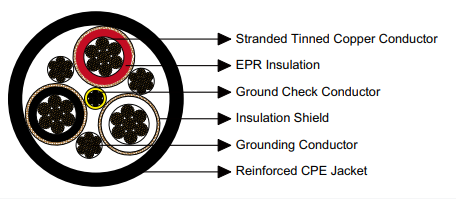
SHD-CGC 2kV three-conductor round portable mining cable with integrated ground check conductor for continuous ground integrity monitoring. Longwall shearers, continuous miners, mobile loaders, drilling equipment. Yellow-insulated ground check conductor, metallic shielding, EPR insulation. ICEA S-75-381 compliant. Four sizes 3×2/0 to 3×350 kcmil, ampacity 243-435A.
SHD-CGC Type Three-Conductor Round Portable Power Cable 2kV with Ground Check Conductor
Advanced Ground Integrity Monitoring System for Enhanced Mining Equipment Safety
Regulatory Standards and Safety Compliance Framework
- ICEA S-75-381 / NEMA WC 58: Industry standard specifications for portable mining power cables incorporating ground check conductor monitoring systems for voltages through 5kV
- ASTM B 172: Specification establishing requirements for rope-lay-stranded copper conductors utilizing bunch-stranded or concentric-stranded construction methodologies
- ASTM B 33: Standard specification for tinned soft or annealed copper wire for electrical applications requiring corrosion resistance in underground mining environments
- CAN/CSA C22.2 No. 96: Canadian Standards Association certification for portable power cables deployed in mining and industrial environments with enhanced safety requirements
Ground Check Conductor: Functional Architecture and Safety Mechanism
The ground check conductor serves a fundamentally different function than the primary equipment grounding conductor. While the equipment grounding conductor provides a low-impedance fault current return path capable of carrying thousands of amperes during ground fault conditions, the ground check conductor carries minimal current under normal circumstances, functioning exclusively as a continuity monitoring circuit.
Equipment Grounding Conductor
- Function: Fault current return pathway
- Current capacity: Sized to carry fault currents
- Connection: Bonded to equipment frames
- Construction: Bare tinned copper conductor
- Location: Integrated within cable assembly
Ground Check Conductor (Yellow)
- Function: Continuity monitoring circuit
- Current capacity: Milliampere monitoring signal
- Connection: Isolated monitoring relay circuit
- Construction: Yellow insulated 16 AWG conductor
- Location: Central position within cable core
Ground monitoring relays continuously inject a low-voltage monitoring signal through the yellow ground check conductor. If the equipment grounding conductor develops a break or high-resistance connection compromising equipment ground integrity, the monitoring circuit detects the fault condition instantaneously. The ground monitoring relay then initiates protective actions including energizing warning indicators, triggering audible alarms, and most critically, opening the main equipment circuit breaker removing power from the equipment before hazardous voltages appear on equipment frames.
This active monitoring architecture provides protection superior to conventional pilot check monitoring systems that only verify cable integrity when equipment is de-energized. Ground check conductor monitoring operates continuously during equipment operation, detecting ground faults immediately as they develop rather than discovering them during subsequent equipment startup sequences. This real-time monitoring capability substantially reduces personnel electrocution risk in underground mining environments.
Cable Construction Engineering and Material Specifications
Power Conductor Assembly
Primary power conductors manufactured using rope-lay stranded annealed copper with comprehensive tin plating on individual wire elements. Stranding configurations from 342 to 888 strands provide superior flexibility for cable reeling applications while maintaining current-carrying capacity. Tin plating prevents copper oxidation in high-humidity underground atmospheres.
Dielectric Insulation Material
Ethylene Propylene Rubber (EPR) compound serves as primary conductor insulation. EPR demonstrates excellent electrical characteristics including high dielectric strength, low power factor, superior resistance to corona formation, and maintained flexibility across temperature extremes from -40°C to +90°C continuous operation in mining environments.
Conductor Shielding System
Individual metallic shields constructed from tinned copper wire braided with reinforcing textile fibers encircle each power conductor. These shields provide electrostatic screening reducing electromagnetic interference, contribute supplementary grounding pathways, and deliver mechanical reinforcement protecting insulation against abrasion damage in mining applications.
Yellow Ground Check Conductor
Dedicated 16 AWG tinned copper conductor with yellow thermoplastic insulation positioned at cable geometric center. Yellow color coding facilitates immediate visual identification during installation and maintenance. The 16 AWG size provides adequate mechanical strength while enabling flexible routing through cable assemblies.
Equipment Grounding Conductor
Bare tinned copper grounding conductor sized proportional to power conductor capacity (ranging from 5 AWG to 1 AWG depending on cable size) provides primary equipment grounding pathway. Located adjacent to ground check conductor ensuring balanced mechanical characteristics during cable flexing in reeling operations.
Reinforced Protective Jacket
Extra-heavy-duty Chlorinated Polyethylene (CPE) outer jacket formulated specifically for mining applications delivers comprehensive protection against abrasion from coal and mineral particles, resistance to flame propagation meeting underground mining safety codes, immunity to petroleum hydrocarbon contamination, and flexibility maintained across operational temperature ranges.
Alternative Jacketing Materials for Specialized Operating Conditions
While CPE represents the industry-standard jacketing material for coal mining applications, alternative elastomeric compounds address specialized environmental requirements. Chlorosulfonated Polyethylene (CSP) provides enhanced resistance to aggressive chemical exposure in metal mining operations utilizing acid leaching processes. Polychloroprene (PCP) delivers improved low-temperature flexibility for mining operations in arctic regions or high-altitude locations. Nitrile Butadiene Rubber (NBR) offers superior resistance to petroleum products and hydraulic fluids common around mobile mining equipment. Polyvinyl Chloride (PVC) serves applications with controlled environmental conditions and reduced cost sensitivity.
For installations demanding maximum mechanical protection in high-abrasion environments, a reinforced dual-layer jacket construction incorporating high-tenacity aramid or polyester fibers between inner and outer elastomeric layers substantially increases puncture resistance and cable service life. This construction proves particularly beneficial for continuous miner cables operating in hard coal seams with significant rock intrusions generating sharp particles.
Thermal and Mechanical Performance Parameters
The 90°C continuous conductor operating temperature establishes the thermal limit for sustained current-carrying operation. Maintaining conductor temperatures below this threshold through appropriate ampacity application and derating for ambient conditions significantly extends EPR insulation service life by reducing thermal aging acceleration. Underground mining environments typically maintain relatively constant ambient temperatures facilitating stable ampacity determination.
The minimum bending radius specification prevents mechanical damage during cable installation and service. Cable routing through equipment cable reels, around structural members, and along cable trays must accommodate this minimum radius. Violation of bending radius specifications induces premature cable failure through conductor strand breakage, insulation cracking, shield discontinuity, and potentially ground check conductor damage compromising safety monitoring functionality.
Complete Technical Specifications and Engineering Data
| Cable Configuration (Cores × AWG/kcmil) | Conductor Strands | Equipment Ground (AWG/kcmil) | Ground Check (AWG/kcmil) | Insulation Thickness (inch / mm) | Jacket Thickness (inch / mm) | Overall Diameter (inch / mm) | Cable Mass (lbs/kft / kg/km) | Current Rating (Amperes) |
|---|---|---|---|---|---|---|---|---|
| 3 × 2/0 AWG | 342 | 5 AWG | 16 AWG (Yellow) | 0.08 / 2.0 | 0.205 / 5.2 | 2.09 / 53.1 | 3400 / 5059 | 243 |
| 3 × 3/0 AWG | 418 | 4 AWG | 16 AWG (Yellow) | 0.08 / 2.0 | 0.205 / 5.2 | 2.21 / 56.1 | 3934 / 5853 | 279 |
| 3 × 4/0 AWG | 532 | 3 AWG | 16 AWG (Yellow) | 0.08 / 2.0 | 0.220 / 5.6 | 2.36 / 59.9 | 4860 / 7231 | 321 |
| 3 × 350 kcmil | 888 | 1 AWG | 16 AWG (Yellow) | 0.95 / 2.4 | 0.250 / 6.3 | 2.81 / 71.4 | 7400 / 11010 | 435 |
Ampacity Determination Methodology: Current-carrying capacity ratings represent calculations performed according to ICEA S-75-381 standard procedures assuming 90°C maximum conductor operating temperature with 40°C ambient air temperature baseline. Underground mining installations typically experience lower ambient temperatures (15-25°C) potentially allowing modest ampacity increases, while surface mining applications in high-temperature climates require ampacity derating. Cable duty cycle characteristics, grouping configurations, and installation methods influence actual permissible current loading in field installations.
Cable Size Selection and Application-Specific Optimization
Engineering Decision Framework for Ground Check Cable Specification
Selecting the appropriate conductor size for mining equipment requiring ground check monitoring involves comprehensive evaluation of electrical performance requirements, equipment duty cycle characteristics, cable length from power center to equipment, voltage drop limitations, and mechanical handling constraints. Unlike flat cable applications where cable profile dimensions prove critical, round cable selections prioritize current-carrying capacity, voltage drop performance, and mechanical flexibility for reeling systems.
3 × 2/0 AWG Configuration
- Ampacity: 243A (baseline capacity)
- Conductor cross-section: 67.4 mm² per phase
- Cable linear mass: 5059 kg/km
- Overall diameter: 53.1 mm (most compact)
- Equipment ground: 5 AWG bare tinned copper
- Optimal applications: Small continuous miners operating in thin coal seams, mobile LHD loaders up to 8 cubic yard capacity, underground drilling rigs under 300 horsepower, conveyor belt drives under 250 horsepower, dewatering pumps 150 horsepower maximum
- Cable length recommendation: Effective for installations under 125 meters maintaining acceptable voltage regulation
- Economic advantage: Lowest material cost and lightest weight for applications meeting ampacity requirements
3 × 3/0 AWG Configuration
- Ampacity: 279A (+15% versus 2/0)
- Conductor cross-section: 85.0 mm² per phase
- Cable linear mass: 5853 kg/km
- Overall diameter: 56.1 mm
- Equipment ground: 4 AWG bare tinned copper
- Optimal applications: Standard continuous miners for medium-thickness coal seams, LHD loaders 10-12 cubic yard capacity, longwall shearer auxiliary systems, underground drilling rigs 300-450 horsepower, mobile crusher primary drives, roof bolting machines with full automation
- Cable length recommendation: Suitable for installations 125-175 meters with acceptable efficiency
- Industry preference: Most commonly specified size for general underground mining equipment with ground check monitoring requirements
3 × 4/0 AWG Configuration
- Ampacity: 321A (+32% versus 2/0)
- Conductor cross-section: 107.2 mm² per phase
- Cable linear mass: 7231 kg/km
- Overall diameter: 59.9 mm
- Equipment ground: 3 AWG bare tinned copper
- Optimal applications: Large continuous miners for thick coal seams, high-capacity LHD loaders exceeding 12 cubic yards, longwall shearer main power systems, high-horsepower conveyor drives exceeding 400 horsepower, large mobile crushers, shuttle cars with heavy-duty motors
- Cable length recommendation: Effective for installations 175-225 meters maintaining good voltage regulation
- Heavy-duty capability: Enhanced thermal margin accommodates sustained heavy loads and frequent equipment starting cycles
3 × 350 kcmil Configuration
- Ampacity: 435A (+79% versus 2/0, maximum capacity)
- Conductor cross-section: 177.3 mm² per phase (largest available)
- Cable linear mass: 11010 kg/km (heaviest)
- Overall diameter: 71.4 mm (largest)
- Equipment ground: 1 AWG bare tinned copper (largest ground conductor)
- Insulation enhancement: Thicker insulation wall (2.4mm versus 2.0mm) for increased dielectric margin
- Optimal applications: Maximum-capacity continuous miners operating in extremely thick coal seams, ultra-heavy-duty mobile equipment requiring highest available current capacity, longwall shearer systems with multiple high-horsepower motors, primary power distribution for largest underground mining equipment, installations requiring future capacity expansion capability
- Cable length recommendation: Engineered for extended installations 225-300+ meters where voltage drop must be minimized despite long cable runs
- Premium specification: Highest ampacity provides maximum operational safety margin and accommodates equipment power upgrades without cable replacement
Ground Check Monitoring System Integration and Safety Protocols
Implementing ground check conductor monitoring requires integration with specialized ground fault detection relays continuously supervising ground circuit continuity. These monitoring relays inject a low-voltage DC monitoring signal (typically 12-24 VDC) through the yellow ground check conductor while simultaneously monitoring the equipment grounding conductor voltage relative to the monitoring signal. Under normal operating conditions with intact ground integrity, the monitoring relay detects the expected voltage relationship between the two conductors.
If the equipment grounding conductor develops a high-resistance connection or complete break compromising ground integrity, the voltage relationship monitored by the ground fault relay changes outside acceptable parameters. The relay immediately initiates protective sequences including activating visual and audible alarms alerting operators to ground fault conditions, energizing lockout circuits preventing equipment restart until ground faults are corrected, and most critically, tripping the main circuit breaker removing power from equipment before hazardous frame voltages can develop.
Mining operations implementing ground check monitoring systems must establish comprehensive safety protocols including daily ground monitor functionality testing before equipment operation, immediate investigation of ground monitor alarm conditions without equipment restart attempts, mandatory ground circuit resistance testing during preventive maintenance intervals, and comprehensive documentation of ground fault events for regulatory compliance and trend analysis identifying recurring ground integrity issues.
The 16 AWG yellow ground check conductor provides adequate mechanical strength for underground mining installations while facilitating flexible routing through cable reeling systems. Yellow insulation color coding enables immediate visual identification during cable termination procedures, reducing installation errors that could compromise ground monitoring functionality. All cable terminations must ensure the yellow ground check conductor connects exclusively to ground monitoring relay inputs without any connection to equipment frames or grounding conductors, as improper connections defeat the monitoring system functionality.


