
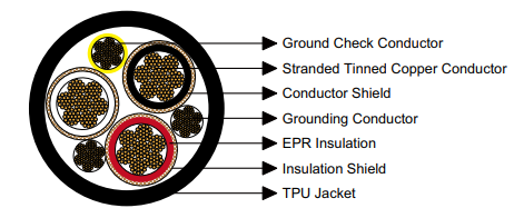
Advanced SHD-GC 25kV portable power cable with premium TPU jacket combining ultra-high voltage capacity with superior flexibility. Ideal for draglines, large shovels, automated mining equipment. Lightweight construction, exceptional abrasion resistance, ICEA S-75-381 certified.
International Support: +86 13855123218
SHD-GC Three-Conductor Round Portable Power Cable featuring Advanced Thermoplastic Polyurethane Jacket Technology – 25kV Ultra High Voltage Classification
Series: SHD-GC | Voltage: 25000V | Jacket: Advanced TPUNext-generation flexible high-voltage power transmission cable combining ultra-high voltage capability with advanced polymer technology for superior mechanical performance and operational efficiency. This innovative SHD-GC variant integrates premium-grade thermoplastic polyurethane jacketing with enhanced dielectric insulation architecture, delivering an optimal balance of electrical capacity, mechanical durability, and handling flexibility. Engineered specifically for modern automated mining operations, large-scale surface excavation equipment, and extreme-environment applications where traditional rubber-jacketed cables present limitations in weight, flexibility, or environmental resistance.
Equipment Applications and Operational Deployment Profiles
This advanced cable configuration addresses the evolving requirements of contemporary mining and industrial operations transitioning toward higher efficiency, increased automation, and improved operational flexibility. The combination of 25kV voltage rating with premium TPU jacket technology delivers unique performance advantages for equipment operating in demanding environments where both electrical capacity and mechanical adaptability are critical. Primary application domains include:
- Modern Walking Dragline Operations: Power supply infrastructure for large walking draglines representing the cornerstone of overburden removal in large-scale surface coal and mineral mining operations worldwide. These massive machines—among the largest mobile equipment ever constructed—demand reliable high-voltage power delivery through cables that withstand continuous mechanical stress while maintaining reasonable weight and flexibility characteristics. The TPU jacket’s exceptional abrasion resistance dramatically extends cable service life in applications where draglines traverse rough terrain and cables experience constant dragging contact with ground surfaces. The material’s superior low-temperature flexibility ensures reliable operation in northern mining regions experiencing extreme winter conditions where conventional rubber compounds become rigid and susceptible to cracking.
- Ultra-Large Electric Mining Shovels: Primary electrical feeders for the largest class of electric rope shovels deployed in open-pit mining worldwide, with bucket capacities ranging from 50 to over 100 cubic yards. These productivity-critical assets require power distribution systems delivering maximum electrical capacity while minimizing cable weight and bulk that would impede shovel mobility or complicate cable handling during repositioning operations. The TPU-jacketed cable provides an optimal weight-to-performance ratio, delivering 25kV capacity in a lighter, more flexible package compared to conventional CPE or rubber-jacketed alternatives, facilitating easier cable management and reducing mechanical stress on cable handling systems.
- Automated Mobile Mining Equipment: Power distribution for next-generation semi-autonomous and autonomous mining equipment incorporating advanced control systems, real-time positioning, and remote operation capabilities. Modern automated mining systems demand reliable, flexible power cables that accommodate frequent equipment repositioning, adapt to varying terrain conditions, and withstand the mechanical demands of autonomous operation patterns that may differ substantially from traditional operator-controlled movement profiles. The TPU jacket’s flexibility and durability characteristics align perfectly with the operational demands of automated systems.
- Large-Scale Dredging Projects: Electrical infrastructure for major hydraulic dredging operations including deep-water port development, waterway maintenance, and offshore mineral extraction. The TPU compound’s excellent hydrolytic stability ensures long-term performance in marine environments with continuous moisture exposure, while the material’s flexibility facilitates cable management aboard dredge vessels and pontoons experiencing continuous motion from wave action and operational vibration.
- Arctic and Extreme Cold Climate Mining: Power transmission for mining operations in northern Canada, Russia, Alaska, and Scandinavia where ambient temperatures regularly fall below -40°C during winter operations. TPU’s remarkable retention of flexibility at extreme low temperatures—substantially superior to conventional rubber and elastomeric compounds—ensures cables remain manageable and resistant to impact damage even in the harshest arctic conditions where competing materials become brittle and prone to catastrophic failure from mechanical shock.
Industry Standards Compliance and Certification Framework
Engineering design and manufacturing processes for this cable configuration strictly conform to established international standards defining requirements for portable and mining power cables. Adherence to these specifications ensures product compatibility with globally-sourced equipment and compliance with electrical safety regulations across diverse jurisdictions:
- ICEA S-75-381 in conjunction with NEMA WC 58: These coordinated specifications published by the Insulated Cable Engineers Association and National Electrical Manufacturers Association constitute the primary standards governing portable and power feeder cable construction, testing, and performance for mining and industrial applications. The standards establish comprehensive requirements for conductor configuration and sizing, insulation system design including enhanced thickness specifications for higher voltage classifications, shielding architecture, jacket material performance characteristics, and rigorous testing protocols including high-voltage dielectric integrity testing, conductor DC resistance verification, and mechanical performance validation under specified conditions.
- ASTM B 172: Specification defining construction parameters for rope-lay-stranded copper conductors with bunch-stranded members for electrical applications. This standard ensures conductors achieve optimal flexibility through proper strand geometry, lay direction sequencing, and dimensional control while maintaining structural integrity and current-carrying capacity necessary for portable cable service involving repeated flexing and mechanical loading.
- ASTM B 33: Standard specification governing tinned copper wire for electrical purposes. This specification establishes comprehensive requirements for tin coating application methodology, minimum coating thickness ensuring effective corrosion protection, adhesion characteristics, and uniformity testing procedures, ensuring tin coating provides long-term protection against oxidation and sulfur-induced corrosion while maintaining electrical conductivity and solderability for field termination procedures.
- CAN/CSA C22.2 No. 96: Canadian Standards Association requirements for portable power cables. Conformance with this specification facilitates cable deployment in Canadian mining and industrial operations where CSA certification may be contractually required or specified by provincial regulatory authorities overseeing mining electrical installations.
Advanced Construction Architecture and Material Technology
High-Flexibility Conductor Design
Phase conductors incorporate premium electrolytic copper wire processed through controlled thermal annealing to optimize ductility while maintaining adequate tensile strength for mechanical loading encountered in portable cable service. Individual copper strands receive protective tin coating applied through electrolytic or hot-dip processes, creating a metallic barrier preventing copper oxidation and sulfur attack that would increase contact resistance between strands and degrade overall conductor performance. Conductor assembly follows rope-lay stranding patterns with multiple concentric layers arranged in alternating lay directions, maximizing flexibility while maintaining structural integrity and circular cross-sectional geometry. Available conductor sizes from 1 AWG through 4/0 AWG provide continuous ampacity ranging from 191 to 327 amperes under standard thermal rating conditions defined by ICEA methodology.
Conductor Stress Control Shield
Each phase conductor receives a factory-applied semiconducting polymeric shield layer extruded directly onto the conductor surface prior to insulation application. This conductive interface layer performs multiple essential electrical functions: eliminates surface irregularities and air gaps at the conductor-insulation boundary that could initiate partial discharge, provides a uniform cylindrical surface ensuring consistent insulation wall thickness, distributes electrical stress evenly throughout the insulation cross-section preventing stress concentrations, and maintains the entire conductor assembly at equipotential eliminating voltage gradients that could accelerate insulation degradation through electrochemical mechanisms.
Enhanced High-Voltage Insulation System
Ethylene Propylene Rubber (EPR) compound engineered specifically for high-voltage portable cable applications forms the primary dielectric barrier. This advanced elastomeric insulation material delivers critical electrical characteristics enabling reliable 25kV operation: extremely high dielectric strength supporting continuous high-voltage operation with substantial safety margin, minimal dielectric loss factor reducing heat generation within the insulation structure, exceptional resistance to electrical treeing and tracking phenomena that can cause progressive insulation failure, and outstanding thermal aging stability maintaining properties through decades of thermal cycling. The EPR formulation demonstrates remarkable environmental resistance including immunity to moisture absorption, resistance to ozone-induced surface cracking, tolerance to mineral oils and hydraulic fluids, and stability under prolonged UV exposure. For 25kV voltage classification, insulation wall thickness measures 0.260 inches (6.6 millimeters)—significantly enhanced compared to lower voltage ratings—providing the robust dielectric barrier essential for ultra-high-voltage portable cable applications.
Insulation Shield and Ground Plane System
A sophisticated dual-layer shield assembly encloses the EPR insulation. The inner shield comprises semiconducting tape applied helically around the insulation exterior, maintaining electrical contact with the insulation surface and confining the electrical field within the insulation structure preventing surface voltage gradients. Over this semiconducting interface, a composite braid combining tinned copper conductor strands with high-strength textile fibers provides: mechanical reinforcement protecting the insulation from impact and abrasion during cable handling, an equipotential conducting surface eliminating electrostatic charging, and a low-impedance fault current pathway enabling protective device operation during ground fault events. The braid maintains continuous electrical connection to the grounding system throughout the cable length.
Ground Monitoring Conductor
A dedicated monitoring conductor fabricated from tinned copper strands extends through the complete cable assembly. This conductor features bright yellow polypropylene insulation enabling instant visual identification during termination and maintenance procedures. The ground check conductor interfaces with monitoring equipment that detects resistance increases indicating grounding system degradation, providing advance warning of developing ground connection problems before they progress to hazardous conditions. This monitoring capability is particularly valuable in high-voltage applications where reliable grounding fundamentally ensures personnel safety and equipment protection.
Equipment Grounding Conductor
A full-size equipment grounding conductor constructed from tinned copper strands is integrated within the cable assembly, sized proportionally to phase conductors ensuring adequate fault current capacity. This conductor provides the primary ground fault current return path, enabling protective devices to rapidly detect and clear fault conditions while limiting dangerous touch voltages during fault events. The grounding conductor maintains electrical connection to all equipment frames and metal enclosures supplied through the cable.
Premium TPU Jacket Technology
The complete cable assembly receives protection from a precision-extruded Thermoplastic Polyurethane (TPU) jacket engineered to deliver superior mechanical and environmental protection. TPU represents an advanced polymer technology offering exceptional performance characteristics ideally suited to demanding portable cable applications: extraordinary abrasion resistance typically demonstrating 5-10 times longer service life compared to conventional rubber compounds in standardized abrasion testing, outstanding cut and tear resistance protecting against damage from sharp objects and impacts, exceptional flexibility retention across an extreme temperature range from -40°C to +90°C with the material remaining pliable at arctic temperatures where rubber compounds become rigid, excellent resistance to mineral oils, hydraulic fluids, and industrial solvents, superior hydrolytic stability ensuring performance in wet environments, and remarkable ozone and UV resistance. Compared to CPE-jacketed cables of identical voltage and conductor sizing, the TPU construction achieves significant weight reduction—approximately 15-18% lighter—improving handling characteristics and reducing mechanical stress on cable support systems and equipment connection points. The black pigmented TPU compound incorporates UV stabilizers and thermal antioxidants for enhanced environmental durability. Jacket wall thickness ranges from 0.265 to 0.295 inches (6.7 to 7.5 millimeters) depending on cable diameter, providing robust mechanical protection while optimizing flexibility and overall cable weight.
Specialized Configuration Options and Custom Engineering
Alternative Jacket Material Selections: While premium TPU provides optimal performance characteristics for most high-voltage portable cable applications, alternative jacket compounds can be manufactured for specialized operating requirements. Available materials include Chlorinated Polyethylene (CPE) for maximum abrasion resistance in extremely severe mechanical environments, Chlorosulfonated Polyethylene (CSP) offering enhanced chemical resistance and weatherability, Polychloroprene (PCP) providing moderate petroleum resistance with good overall properties, Nitrile Butadiene Rubber (NBR) delivering superior resistance to oils and hydraulic fluids, and Polyvinyl Chloride (PVC) for applications with moderate environmental demands and economic constraints.
Reinforced Multi-Layer Construction: For extreme-duty applications where cables encounter severe mechanical abuse including continuous dragging over rough surfaces, impact from falling materials, or cutting forces from sharp debris, a reinforced dual-layer jacket incorporating high-strength aramid or polyester fiber reinforcement between inner and outer jacket layers can be engineered. This advanced construction substantially increases cut propagation resistance, dramatically improves tear strength, and extends cable operational lifetime in the most demanding service conditions.
Performance Specifications and Operating Characteristics
Minimum Installation Bending Radius: Eight times nominal cable outside diameter. This specification defines the minimum radius permissible during installation, operation, and maintenance activities without risking internal component damage. Tighter bending can cause conductor strand displacement, insulation stress concentrations, or shield damage potentially resulting in premature failure. All cable routing including termination points, support locations, and equipment connections must maintain this minimum radius.
Maximum Sustained Conductor Temperature: 90°C (194°F). This represents the maximum continuous conductor operating temperature without degrading insulation properties or reducing service life. The EPR insulation system maintains complete electrical and mechanical integrity at this temperature indefinitely. Current ratings are established based on this maximum conductor temperature combined with defined ambient conditions.
Operating Temperature Range: The cable maintains full electrical performance and mechanical flexibility across ambient temperatures from -40°C to +70°C. The TPU jacket retains exceptional pliability at extreme low temperatures—substantially superior to conventional rubber compounds—while the EPR insulation resists thermal degradation at elevated temperatures. This extraordinary temperature range enables deployment across diverse geographical regions and climatic conditions from arctic mining operations to tropical surface mines.
Voltage Withstand Capability: The enhanced insulation architecture provides continuous 25kV phase-to-ground operation with substantial safety margin. Factory high-potential testing verifies insulation integrity at voltages significantly exceeding operational levels, ensuring adequate margin for transient overvoltages and switching surges.
Weight Advantage: The TPU jacket construction achieves approximately 15-18% weight reduction compared to equivalent CPE-jacketed cables, improving handling characteristics, reducing installation labor requirements, and minimizing mechanical loading on cable support systems and equipment connection points. This weight advantage translates directly to operational efficiency improvements and reduced installation costs for large cable installations.
Complete Technical Data and Performance Specifications
The comprehensive specification table below presents complete dimensional, electrical, and physical characteristics for all standard cable configurations within the SHD-GC 25kV TPU-jacketed product line. Conductor sizing follows American Wire Gauge (AWG) standards with numerical designations inversely proportional to cross-sectional area. Ampacity values are calculated using ICEA S-75-381 thermal modeling methodology assuming 90°C maximum conductor temperature and 40°C ambient air temperature representing typical mining and industrial thermal conditions.
| Configuration | Strand Quantity | Ground Size | Monitor Size | Insulation | Jacket | Overall OD | Weight | Ampacity |
|---|---|---|---|---|---|---|---|---|
| (Conductors) | (Strands) | (AWG) | (AWG) | inch (mm) | inch (mm) | inch (mm) | lbs/kft (kg/km) | (Amps) |
| 3 × 1 AWG | 259 | 5 AWG | 8 AWG | 0.260 (6.6) | 0.265 (6.7) | 2.95 (74.9) | 4410 (6561) | 191 |
| 3 × 1/0 AWG | 266 | 4 AWG | 8 AWG | 0.260 (6.6) | 0.265 (6.7) | 3.05 (77.5) | 4866 (7240) | 218 |
| 3 × 2/0 AWG | 323 | 3 AWG | 8 AWG | 0.260 (6.6) | 0.280 (7.1) | 3.20 (81.3) | 5560 (8272) | 249 |
| 3 × 3/0 AWG | 418 | 2 AWG | 8 AWG | 0.260 (6.6) | 0.280 (7.1) | 3.33 (84.6) | 6192 (9213) | 286 |
| 3 × 4/0 AWG | 532 | 1 AWG | 8 AWG | 0.260 (6.6) | 0.295 (7.5) | 3.50 (88.9) | 7110 (10578) | 327 |
Performance Characteristics Across Conductor Range
Optimal cable size selection requires comprehensive analysis of multiple engineering factors: required continuous current capacity for connected loads, permissible voltage drop calculations at maximum power transmission distance, mechanical flexibility requirements for specific equipment mobility patterns and cable routing constraints, available installation space at termination points and along cable pathways, mechanical handling equipment capacity for cable deployment and maintenance, and comprehensive lifecycle cost analysis incorporating procurement, installation, operational efficiency, and maintenance expenses. The following analysis examines key performance attributes across the available conductor size range:
Compact Configuration (1 AWG)
- Current Capacity: 191 amperes continuous rating
- Flexibility Profile: Maximum flexibility with 23.6-inch minimum bend radius
- Mass Profile: Lightest option at 4410 pounds per thousand feet
- Application Profile: Moderate-power equipment, secondary systems, auxiliary machinery
- Installation Benefits: Easiest handling and routing, minimal support requirements
- Economic Benefits: Lowest initial cost, reduced transportation expense, simplified termination
Standard Configuration Range (1/0 AWG – 2/0 AWG)
- Current Capacity: 218 to 249 amperes continuous rating
- Flexibility Profile: Excellent flexibility with 24.4 to 25.6-inch minimum bend radius
- Mass Profile: Moderate weight at 4866 to 5560 pounds per thousand feet
- Application Profile: Standard draglines, typical shovels, general dredging, automated equipment
- Installation Benefits: Optimal ampacity-to-flexibility balance, standard handling equipment suitable
- Economic Benefits: Excellent performance-to-cost ratio, most common specification for general applications
High-Capacity Configuration Range (3/0 AWG – 4/0 AWG)
- Current Capacity: 286 to 327 amperes continuous rating
- Flexibility Profile: Good flexibility with 26.6 to 28.0-inch minimum bend radius
- Mass Profile: Higher weight at 6192 to 7110 pounds per thousand feet
- Application Profile: Large draglines, ultra-class shovels, high-capacity dredges, major drilling operations
- Installation Benefits: Maximum ampacity reduces voltage drop and conductor losses, mechanical handling required
- Economic Benefits: Essential for high-power applications, optimizes electrical system efficiency
Installation Methodology and Maintenance Best Practices
Achieving maximum cable service life and ensuring safe operation throughout the cable’s operational period demands strict adherence to proper installation procedures and implementation of comprehensive maintenance programs. Prior to installation, cables should remain on manufacturer reels under protective covering shielding from direct sunlight and precipitation. Installation should proceed within appropriate temperature ranges where jacket and insulation materials maintain adequate flexibility—for cold weather installations below 0°C, cables may require storage in heated facilities or gradual warming prior to handling, while hot weather installations above 40°C should proceed during cooler daily periods to prevent jacket surface damage.
During cable pulling operations, mechanical forces must be applied through properly installed conductor pulling grips or eyes distributing stress across all phase conductors rather than depending on jacket tensile strength which could lead to jacket separation from the underlying cable components. Maximum permissible pulling tension should be calculated based on total conductor cross-sectional area, typically limited to approximately 0.008 times aggregate circular mil area to prevent strand damage. All cable routing including termination zones, intermediate support points, and equipment connection locations must maintain the specified minimum eight-diameter bending radius. Support spacing must be engineered to prevent excessive sag while avoiding compression damage—typical support intervals range from four to seven feet depending on cable size, routing orientation, and external loading conditions.
Ongoing maintenance protocols should incorporate regular systematic visual inspection examining jacket condition for cuts, abrasions, foreign object embedment, localized deformation indicating internal damage, or surface degradation from environmental exposure. Electrical diagnostic testing employing calibrated high-voltage insulation resistance measurement instrumentation should be performed at scheduled intervals, with results documented and analyzed against baseline values and manufacturer acceptance criteria. Ground system testing verifies continuing integrity of equipment grounding and ground check conductors. Cable sections exhibiting visible damage, insulation resistance degradation below acceptable limits, or ground system irregularities must be immediately de-energized and withdrawn from service. Repair versus replacement determinations should be made by qualified electrical engineering professionals after comprehensive evaluation of damage nature, extent, and safety implications.
Engineering Consultation and Custom Cable Solutions
Our technical engineering team provides comprehensive application support services including detailed system voltage drop calculations, thermal analysis for specific operating conditions, custom specification development for unique requirements, and installation planning guidance. We maintain manufacturing flexibility for rapid delivery of standard configurations and engineering capability for custom cable designs addressing specialized operational challenges.
Technical Support: [email protected] | Direct Contact: +86 13855123218
Technical Documentation Author
Michael R. Stevens, M.Eng., P.E. | Dragline Electrical Systems Engineering Specialist | 28 Years Global Experience
This comprehensive technical specification document was authored by Michael R. Stevens, a Professional Engineer licensed in Wyoming and Western Australia with extensive international experience in dragline electrical systems and large-scale surface mining operations. Michael earned his Bachelor of Science degree in Electrical Engineering from Montana Tech of the University of Montana, followed by a Master of Engineering in Power Systems from the University of Wyoming with specialized focus on high-voltage mining electrical distribution.
His professional career encompasses 28 years across some of the world’s largest surface coal and mineral mining operations. Michael served 12 years as Senior Electrical Engineer for Peabody Energy’s North Antelope Rochelle Mine in Wyoming’s Powder River Basin—one of the world’s largest coal mining complexes—where he was responsible for electrical infrastructure supporting 15 walking draglines and numerous electric shovels. This role provided extensive hands-on experience with high-voltage portable cable performance, including pioneering work implementing lighter TPU-jacketed cables to improve handling efficiency and reduce cable-related downtime.
Subsequently, he spent nine years as Chief Electrical Engineer for BHP’s Mt. Arthur Coal Mine in Australia’s Hunter Valley, overseeing electrical systems for dragline operations and managing the mine’s transition to higher voltage distribution systems. This international experience provided valuable exposure to different operating philosophies, equipment configurations, and regulatory frameworks. Most recently, Michael has worked seven years as an independent consulting engineer specializing in dragline electrical system optimization, high-voltage cable selection, and failure analysis for major mining companies worldwide.
Michael maintains active membership in the Institute of Electrical and Electronics Engineers (IEEE) Industry Applications Society, the Society for Mining, Metallurgy & Exploration (SME), and the Australasian Institute of Mining and Metallurgy (AusIMM). He has published numerous technical papers on dragline electrical systems, portable cable selection criteria, and maintenance optimization strategies in peer-reviewed mining industry journals. He serves on technical committees addressing mining electrical safety standards and has presented at multiple international mining conferences. His expertise combines rigorous engineering analysis with practical operational experience gained from decades working in the demanding surface mining environments where these high-voltage cables must deliver reliable performance.


[…] Feichun — SHD-GC 25 kV TPU: contexto de draglines, palas grandes y TPU; no sustituye la ficha del modelo solicitado. […]