
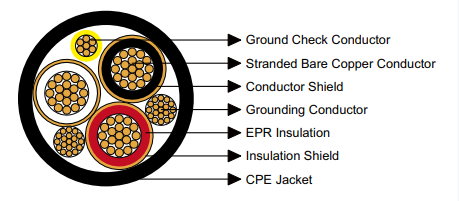
Industrial MP-GC 5kV mine power feeder cable with CPE jacket for permanent underground electrical distribution. Designed for duct, conduit, direct burial installations. EPR insulated, bare copper conductors, 6 AWG to 500 kcmil. ICEA S-75-381 certified for mine distribution systems.
International Inquiries: +86 13855123218
MP-GC Three-Conductor Mine Power Feeder Cable with Chlorinated Polyethylene Jacket – 5kV Voltage Classification
Type: MP-GC | Rating: 5000V | Application: Fixed InstallationPermanent-installation electrical distribution cable engineered specifically for underground mine power distribution systems requiring stationary interconnections between electrical substations, transformer stations, and load centers. This MP-GC series represents specialized fixed-installation cable design incorporating robust construction suitable for long-term buried installations, placement in underground conduit systems, routing through ventilation airways, and mounting on mine infrastructure. Unlike portable trailing cables designed for mobile equipment, mine power feeder cables provide the permanent electrical backbone infrastructure distributing power throughout underground mining complexes and supporting critical ventilation, pumping, and material handling systems.
Distribution System Applications and Installation Methods
Mine power feeder cables serve as the permanent electrical arteries of underground mining operations, carrying power from surface substations or underground power centers to distributed load points throughout the mine. These stationary cables remain in place for extended periods—often years—requiring construction optimized for long-term reliability rather than the flexibility characteristics essential for portable equipment cables. Primary installation applications include:
- Underground Substation Interconnections: Primary and secondary distribution cables connecting main mine substations to sectional substations distributed throughout underground workings. These trunk distribution circuits carry substantial power loads serving multiple downstream branch circuits and must provide reliable service under continuous loading conditions. Cables may be installed in dedicated cable drifts, mounted on cable hangers along haulage entries, or placed in underground conduit banks depending on mine design and local conditions.
- Transformer Feeder Circuits: Power supply cables from distribution switchgear to step-down transformers located throughout the mine to provide appropriate voltage levels for various loads. These feeder runs often span considerable distances—hundreds or thousands of feet—requiring careful voltage drop analysis and conductor sizing to maintain acceptable voltage regulation at transformer primary terminals.
- Direct Burial Installations: Underground cables placed directly in excavated trenches without conduit or duct protection. Direct burial applications occur in permanent mine entries where cable routing follows established transportation infrastructure. The cable’s CPE jacket provides mechanical protection and moisture resistance essential for long-term earth contact without deterioration. Direct burial reduces installation costs compared to conduit systems while providing adequate protection in stable ground conditions.
- Conduit and Duct Bank Systems: Cable installations within rigid metal conduit, PVC conduit, or HDPE duct systems providing enhanced mechanical protection in high-traffic areas or locations subject to ground movement. Conduit installation facilitates future cable replacement or circuit additions without excavation and provides superior protection against mechanical damage from roof bolting equipment, mobile machinery, or roof falls common in underground mining environments.
- Aerial Cable Installation: Mounting cables on cable trays, ladder racks, or cable hangers suspended from mine roof support systems along haulage drifts, main entries, and access tunnels. Aerial installation provides easy access for inspection and reduces exposure to floor water accumulation while maintaining required clearances from mobile equipment traffic. This method is common in well-established permanent mine entries with stable roof conditions.
- Ventilation System Power Distribution: Dedicated circuits supplying power to main mine ventilation fans, booster fans, and air circulation equipment critical for maintaining safe air quality throughout underground workings. These circuits demand exceptional reliability as ventilation system failures can require immediate mine evacuation.
- Pumping Station Power Feeders: Electrical supply to main drainage pumping stations, sump pumps, and dewatering systems managing groundwater inflow. Reliable pump station power prevents flooding of mine workings that could halt operations and create safety hazards.
Applicable Standards and Regulatory Compliance
Manufacturing specifications for mine power feeder cables address the unique requirements for permanent underground electrical installations, conforming to industry standards governing construction, materials, and performance characteristics:
- ICEA S-75-381 and NEMA WC 58: Insulated Cable Engineers Association and National Electrical Manufacturers Association standards providing comprehensive requirements for mining cables including both portable and stationary types. For mine power feeders, these standards establish conductor sizing, insulation thickness requirements for various voltage levels, shielding specifications, jacket material properties, and testing protocols ensuring cables meet performance requirements for underground mining service.
- ASTM B-8: Standard specification for concentric-lay-stranded copper conductors using hard, medium-hard, or soft copper wire. This specification applies to stationary cables where flexibility requirements are less stringent compared to portable applications. The standard defines stranding configurations, dimensional tolerances, and mechanical properties appropriate for fixed-installation conductors. Mine feeder cables typically use Class B stranding with 7, 19, or 37 individual strands depending on conductor size—significantly less flexible than the hundreds of strands in portable cable conductors but adequate for installations involving limited bending during placement.
- CAN/CSA C22.2 No. 96: Canadian Standards Association requirements for portable and stationary mining cables, providing additional verification of construction adequacy and facilitating cable deployment in Canadian mining operations where CSA certification may be specified by mine operators or provincial mining regulatory authorities.
Detailed Construction Architecture and Component Materials
Phase Conductor Design
Current-carrying phase conductors utilize annealed bare copper wire assembled in concentric-lay stranding patterns as defined by ASTM B-8. Conductor stranding for mine feeder cables employs 7-strand, 19-strand, or 37-strand configurations depending on conductor size, providing adequate flexibility for installation while maintaining structural rigidity appropriate for permanent installations. This stranding is substantially less flexible than portable cable conductors but sufficient for the limited bending encountered during cable pulling through conduit or placement in trenches. The bare copper (uncoated) construction is appropriate for permanent installations where the conductor remains protected within the insulation system without exposure to moisture or corrosive elements that would necessitate tinning. Conductor sizes range from 6 AWG through 500 kcmil, accommodating continuous current loads from 93 amperes through 536 amperes under standard thermal rating conditions.
Semiconducting Conductor Shield
Each phase conductor receives a factory-applied conducting layer extruded over the bare copper surface prior to insulation application. This semiconducting shield establishes intimate contact with the conductor, eliminates air voids at the conductor-insulation interface that could initiate partial discharge, and provides uniform radial electrical stress distribution within the insulation system. The conducting layer ensures the entire conductor assembly remains at the same electrical potential, preventing localized voltage concentrations that could accelerate insulation degradation.
EPR Primary Insulation
Ethylene Propylene Rubber (EPR) compound forms the primary dielectric barrier around each phase conductor. EPR was selected for its excellent electrical properties including high dielectric strength, low dielectric loss, and superior resistance to electrical treeing—the progressive formation of conductive channels through insulation under electrical stress. The material demonstrates outstanding thermal aging characteristics maintaining properties through decades of continuous operation at rated temperature. EPR exhibits excellent moisture resistance critical for underground installations where humidity approaches 100% and water infiltration is common. The compound also resists mineral oils, diesel fuel, and lubricants encountered in mining environments. Insulation thickness measures 0.09 inches (2.3mm) providing adequate dielectric strength for 5kV voltage rating with appropriate safety margin per ICEA standards.
Insulation Shield and Ground Plane
The EPR insulation receives a semiconducting layer applied over the outer insulation surface, establishing electrical contact with the insulation and confining the dielectric field within the insulation structure. Over this semiconducting layer, a copper tape shield is applied helically or longitudinally, providing a low-impedance ground plane surrounding each insulated conductor. This metallic shield serves multiple critical functions: provides a path for charging current generated by cable capacitance, enables ground fault detection by protective relaying, limits electromagnetic interference from cable circuits, and provides mechanical protection for the underlying insulation layers.
Ground Check Conductor
An independent monitoring conductor fabricated from bare copper runs parallel to the three phase conductors throughout the cable assembly. This conductor features bright yellow polypropylene insulation for immediate visual identification during cable termination and testing procedures. The ground check conductor enables continuous monitoring of grounding system integrity through impedance measurement techniques, providing early detection of ground connection degradation before hazardous conditions develop—particularly critical in underground mining where reliable grounding is fundamental to personnel safety and ground fault protection schemes.
Equipment Grounding Conductor
A full-size equipment grounding conductor constructed from tinned copper strands is incorporated within the cable assembly, sized according to National Electrical Code and mine safety regulations based on phase conductor ampacity. This grounding conductor provides the primary fault current return path during ground faults, ensuring protective devices can detect and clear faults rapidly while limiting touch voltages and transferred potentials to safe levels. The tinning provides corrosion resistance in the humid underground environment.
CPE Outer Jacket
The complete cable assembly is enclosed in a Chlorinated Polyethylene (CPE) jacket providing environmental protection and mechanical durability for underground installation. CPE offers an excellent balance of properties for stationary mining cables: good abrasion resistance for cable pulling operations, excellent moisture resistance for direct burial and wet location service, good resistance to mineral oils and diesel fuel, superior flame resistance limiting fire propagation in underground entries, good low-temperature flexibility for cold climate surface installations feeding underground systems, and excellent aging characteristics for multi-decade service life. The black compound incorporates carbon black for UV protection and antioxidants for thermal stability. Jacket thickness ranges from 0.11 inches (2.8mm) for smaller cables to 0.14 inches (3.6mm) for larger sizes, providing robust mechanical protection for the installation environment while maintaining reasonable cable diameter.
Alternative Materials and Configuration Options
Alternative Jacket Compounds: While CPE provides excellent overall performance for most mine feeder applications, alternative jacket materials can be specified for unique installation environments. Chlorosulfonated Polyethylene (CSP) offers enhanced chemical resistance and superior weathering for cables with significant surface exposure. Polychloroprene (PCP) provides moderate petroleum resistance with good flexibility. Nitrile Butadiene Rubber (NBR) delivers superior oil resistance for installations in proximity to diesel equipment fueling stations or maintenance areas with heavy petroleum contamination. Polyvinyl Chloride (PVC) offers economical performance for dry, well-protected installations. Thermoplastic Polyurethane (TPU) provides enhanced abrasion resistance for installations subject to mechanical abuse during placement or operation.
Physical Characteristics and Installation Parameters
Minimum Bending Radius: Twelve times the cable overall diameter. This specification—notably less flexible than portable cables requiring eight times diameter—reflects the permanent installation nature where cables experience bending primarily during initial placement rather than continuous flexing during operation. The larger bend radius protects insulation and shielding systems from damage during cable pulling while acknowledging that stationary cables do not require the extreme flexibility of trailing equipment cables.
Maximum Conductor Operating Temperature: 90°C (194°F) continuous. This thermal rating represents the maximum sustained conductor temperature without degrading insulation properties or reducing service life. The EPR insulation maintains full electrical and mechanical integrity at this temperature throughout multi-decade service periods typical of permanent mine infrastructure.
Voltage Rating: 5000 volts phase-to-ground. This voltage class serves typical mine distribution systems where surface power at 4160V or 4800V is distributed underground. The insulation system provides continuous operation capability with adequate margin for transient overvoltages from switching operations or lightning-induced surges.
Installation Temperature Range: Cable installation should occur within temperature ranges where jacket and insulation materials maintain adequate flexibility—typically above -10°C for CPE-jacketed cables. For installations in colder conditions, cables may require storage in heated facilities or gradual warming prior to handling to prevent jacket cracking during bending.
Complete Technical Specifications and Current Ratings
The following comprehensive data table presents complete specifications for all standard conductor sizes within the MP-GC 5kV series. Ampacity values are calculated per ICEA S-75-381 methodology assuming 90°C maximum conductor temperature and 40°C ambient conditions typical of underground mine environments. Actual current-carrying capacity may vary based on installation method (duct, direct burial, or aerial), soil thermal resistivity for buried installations, cable grouping, and load factors.
| Configuration | Conductor Strands | Ground Size | Check Size | Insulation | Jacket | Overall OD | Weight | Ampacity |
|---|---|---|---|---|---|---|---|---|
| (Cores × Size) | (Count) | (AWG/kcmil) | (AWG) | inch (mm) | inch (mm) | inch (mm) | lbs/kft (kg/km) | (Amperes) |
| 3 × 6 AWG | 7 | 10 AWG | 8 AWG | 0.09 (2.3) | 0.11 (2.8) | 1.30 (33.0) | 1060 (1577) | 93 |
| 3 × 4 AWG | 7 | 8 AWG | 8 AWG | 0.09 (2.3) | 0.11 (2.8) | 1.41 (35.8) | 1441 (2144) | 122 |
| 3 × 2 AWG | 7 | 6 AWG | 8 AWG | 0.09 (2.3) | 0.11 (2.8) | 1.47 (37.3) | 1827 (2718) | 159 |
| 3 × 1 AWG | 19 | 5 AWG | 8 AWG | 0.09 (2.3) | 0.11 (2.8) | 1.54 (39.1) | 2168 (3226) | 184 |
| 3 × 1/0 AWG | 19 | 4 AWG | 8 AWG | 0.09 (2.3) | 0.11 (2.8) | 1.63 (41.4) | 2602 (3871) | 211 |
| 3 × 2/0 AWG | 19 | 3 AWG | 8 AWG | 0.09 (2.3) | 0.11 (2.8) | 1.72 (43.7) | 3010 (4478) | 243 |
| 3 × 3/0 AWG | 19 | 2 AWG | 8 AWG | 0.09 (2.3) | 0.14 (3.6) | 1.89 (48.0) | 3265 (4859) | 279 |
| 3 × 4/0 AWG | 19 | 1 AWG | 8 AWG | 0.09 (2.3) | 0.14 (3.6) | 2.01 (51.0) | 4190 (6234) | 321 |
| 3 × 250 kcmil | 37 | 1/0 AWG | 8 AWG | 0.09 (2.3) | 0.14 (3.6) | 2.10 (53.3) | 4825 (7179) | 355 |
| 3 × 350 kcmil | 37 | 2/0 AWG | 8 AWG | 0.09 (2.3) | 0.14 (3.6) | 2.31 (58.7) | 6062 (9019) | 435 |
| 3 × 500 kcmil | 37 | 4/0 AWG | 8 AWG | 0.09 (2.3) | 0.14 (3.6) | 2.59 (65.8) | 8427 (12538) | 536 |
Installation Method Characteristics and Sizing Considerations
Proper conductor sizing for mine feeder cables requires comprehensive analysis considering multiple factors beyond simple ampacity: load characteristics including continuous vs. intermittent loading patterns, maximum demand calculations incorporating diversity factors for multiple connected loads, voltage drop limitations necessary to maintain adequate voltage at load points, fault current considerations ensuring protective devices can detect ground faults, and installation method influencing thermal dissipation characteristics:
Direct Burial Installation
- Thermal Characteristics: Good heat dissipation through earth contact, affected by soil thermal resistivity and moisture content
- Installation Method: Cables placed in excavated trenches minimum 24-36 inches deep, sand bedding recommended
- Advantages: Lower installation cost, good thermal performance in moist soil, simple installation
- Considerations: Requires stable ground conditions, difficult cable replacement, potential damage from ground movement
- Typical Applications: Permanent mine entries, established haulage ways, stable geologic conditions
Conduit and Duct Installation
- Thermal Characteristics: Reduced heat dissipation compared to direct burial, air gap provides thermal resistance
- Installation Method: Cables pulled through rigid or flexible conduit, underground duct banks with multiple circuits
- Advantages: Superior mechanical protection, enables future cable replacement, protects against ground movement
- Considerations: Higher installation cost, reduced ampacity due to thermal limitations, fill ratio restrictions
- Typical Applications: High-traffic areas, unstable ground zones, locations requiring multiple circuit capacity
Aerial/Tray Installation
- Thermal Characteristics: Excellent heat dissipation through convection in ventilated airways, highest ampacity ratings
- Installation Method: Mounted on cable hangers, ladder tray, or cable tray systems suspended from roof support
- Advantages: Excellent cooling, easy inspection and maintenance access, simple installation and removal
- Considerations: Requires adequate clearances from mobile equipment, exposure to physical damage, roof support requirements
- Typical Applications: Main haulage entries, well-ventilated permanent airways, areas with stable roof conditions
Installation Guidelines and Long-Term Maintenance
Achieving maximum cable service life in permanent mine installations requires careful installation practices and periodic inspection programs. Prior to installation, cables should be stored on reels protected from direct sunlight and moisture. Installation should avoid excessive pulling tension that could damage conductors or insulation—typical maximum tension limits to 0.008 times circular mil area for copper conductors. All bends must respect the twelve-diameter minimum radius specification to prevent insulation damage.
For direct burial installations, trench bottoms should be cleared of rocks and debris, with sand bedding providing cushioning and improved thermal contact. Backfill should be tamped in layers to prevent voids while avoiding excessive mechanical stress on the cable. Underground conduit installations require proper sizing maintaining allowable fill ratios and avoiding sharp bends that create high pulling tensions or cable damage. Pulling lubricants approved for electrical cables should be used for long conduit runs.
Periodic inspection programs should examine exposed cable sections for jacket damage, check termination integrity at switchgear and junction boxes, and verify ground continuity through testing. Insulation resistance testing using appropriate high-voltage megohmmeters should be performed at commissioning and at regular intervals thereafter, with results documented and trended to detect deterioration. Any cables showing degraded insulation resistance or physical damage should be investigated promptly to prevent failures that could disrupt critical mine systems.
Mine Electrical Infrastructure Engineering Support
Our technical engineering staff provides comprehensive application support for mine electrical distribution system design including load flow analysis, voltage drop calculations, fault current studies, cable sizing recommendations, and installation method consultation. We supply complete cable system solutions from substation feeders to branch circuit distribution.
Technical Consultation: [email protected] | Project Inquiries: +86 13855123218
Technical Documentation Author
Gregory P. Walsh, P.E. | Mine Electrical Systems Design Engineer | 27 Years Underground Mining Experience
This mine power feeder cable specification was authored by Gregory P. Walsh, a Professional Engineer licensed in West Virginia and Kentucky with extensive experience in underground mine electrical system design and installation. Gregory earned his Bachelor of Science degree in Electrical Engineering from the University of Kentucky, with specialized coursework in power systems and industrial electrical design.
His professional career encompasses 27 years in coal and metal mining electrical engineering. Gregory served 13 years as Senior Electrical Engineer for Alpha Natural Resources (subsequently acquired by Contura Energy), where he was responsible for electrical infrastructure design across multiple underground coal mining operations in Appalachia. This role involved extensive work with mine power distribution systems including substation design, feeder cable sizing and routing, transformer placement optimization, and protective relaying coordination. He gained direct hands-on experience with cable installation methods, failure analysis, and maintenance program development.
Subsequently, he spent nine years as Chief Electrical Engineer for Massey Energy’s southern West Virginia operations, overseeing electrical systems for underground longwall and continuous miner sections. This position involved managing electrical infrastructure for some of the nation’s most productive underground coal mines, requiring reliable high-capacity distribution systems supporting intensive mechanized mining operations. Most recently, Gregory has worked five years as an independent consulting engineer specializing in mine electrical system design, regulatory compliance, and safety analysis for underground mining operations.
Gregory maintains active membership in the Institute of Electrical and Electronics Engineers (IEEE) Industry Applications Society, the Society for Mining, Metallurgy & Exploration (SME), and serves as a registered Professional Engineer in multiple coal-producing states. He has extensive experience with Mine Safety and Health Administration (MSHA) electrical regulations and has provided expert testimony in investigations of mine electrical incidents. His expertise combines rigorous electrical engineering analysis with practical operational knowledge gained from decades working in the challenging underground environments where these distribution cables must deliver decades of reliable service supporting critical mine infrastructure and safety systems.


