

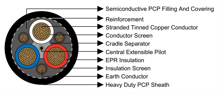
Professional engineering specifications for AS/NZS 1802:2003 Type 241 mining cables featuring overall semiconductive screen protection and three interstitial earth conductors. Complete technical data for EPR insulated continuous miner feeder cables, pump supply cables, and main distribution conductors rated 1.1-11kV with advanced breach protection technology.
AS/NZS 1802:2003 Type 241 Mining Cable
Overall Semiconductive Screen Protection System | Enhanced Earth Fault Detection | Voltage Rating: 1.1kV to 11kV
Product Applications and Technological Innovation
Type 241 trailing cables represent the pinnacle of mining cable safety engineering, incorporating overall semiconductive screening technology that fundamentally transforms protective earth functionality. This advanced configuration delivers comprehensive sheath breach detection capabilities unavailable in conventional mining cable constructions, establishing Type 241 as the optimal selection for continuous mining machinery, submersible pump installations, and main distribution feeders where maximum personnel protection remains paramount.
The distinguishing characteristic of Type 241 design centers on the overall semiconductive polychloroprene (PCP) layer enveloping the entire conductor assembly. This semiconductive barrier creates a protective equipotential zone ensuring that any mechanical breach penetrating the outer sheath immediately contacts the semiconductive screen before potentially reaching energized power conductors. This contact initiates instantaneous earth fault current flow enabling rapid protective device operation, dramatically reducing electrical shock hazards compared to conventional cable designs lacking overall screening.
Overall Semiconductive Screen Technology: Revolutionary Protection Mechanism
Unlike traditional cable constructions where mechanical sheath damage may expose live conductors before protective systems activate, Type 241’s overall semiconductive screen establishes a comprehensive safety barrier. Any penetrating object—whether mining pick, conveyor chain, roof bolt, or sharp rock fragment—must traverse the semiconductive layer before contacting power conductors. The semiconductive material’s controlled electrical properties immediately conduct fault current to the three interstitial earth conductors, triggering instantaneous circuit breaker operation typically within 40-200 milliseconds depending upon protective device settings and fault current magnitude.
Continuous Miner Main Feeders
Primary power supply cables for continuous mining machines operating in confined underground coal seams. Type 241’s overall screening provides critical protection where cable exposure to cutting drum impact, roof falls, and machinery pinch points creates elevated sheath breach risk. Triple earth conductors ensure minimal earth loop impedance facilitating sensitive ground fault protection coordination.
Submersible Pump Installations
Power supply cables for dewatering pumps operating in sumps, shaft bottoms, and underground water accumulation zones. Overall semiconductive screen provides essential protection in wet environments where insulation degradation and water ingress create elevated electric shock hazards. Enhanced earth conductor sizing accelerates fault detection in high-resistivity water conditions.
Main Distribution Circuits
Underground distribution feeders connecting substation equipment to localized load centers throughout mining operations. Type 241 construction ensures maximum personnel protection along cable routes traversing access roadways where vehicle traffic, material handling, and maintenance activities increase mechanical damage probability.
Shuttle Car Power Supply
Flexible feeder cables supplying battery haulers and shuttle cars transporting coal from continuous miners to conveyor transfer points. Overall screening protection proves essential where cable dragging across uneven floor conditions and exposure to coal spillage create continuous mechanical stress and abrasion conditions.
Sheath Breach Protection Sequence
Stage 1 – Normal Operation: Outer PCP sheath provides environmental protection while overall semiconductive screen remains at ground potential through connection to interstitial earth conductors. No current flows in screening layer.
Stage 2 – Sheath Penetration: Mechanical breach penetrates outer sheath exposing overall semiconductive screen. Penetrating object contacts semiconductive layer establishing conductive pathway to earth system.
Stage 3 – Fault Current Initiation: If breach progresses toward insulated power conductors, any contact with conductor insulation screen or conductor surface initiates earth fault current flow through overall semiconductive screen and earth conductors back to supply transformer neutral.
Stage 4 – Protective Device Operation: Fault current magnitude (typically 10-1000 amperes depending upon voltage level and earth system impedance) causes circuit breaker or earth leakage relay activation within milliseconds, disconnecting power before significant shock current can flow through human contact.
Standards Compliance and Regulatory Framework
Type 241 cable manufacturing adheres to comprehensive Australian and New Zealand electrical standards governing underground mining cable systems with particular emphasis on protective conductor systems, earth fault protection sensitivity, and mechanical integrity requirements for mechanized coal extraction environments.
- AS/NZS 1802:2003: Primary specification standard establishing construction requirements, material properties, and performance testing protocols for reeling and trailing cables utilized in mining operations. Type 241 designation represents advanced protection configuration within this standard incorporating overall semiconductive screening technology.
- AS/NZS 1125: Conductor manufacturing standard defining stranding configurations, annealing processes, and electrical conductivity requirements for copper conductors employed in flexible cable assemblies. Governs power conductors, earth conductors, and pilot conductor constructions.
- AS/NZS 3808: Electrical safety standard establishing installation practices, earthing system requirements, protective device coordination, and earth fault protection sensitivity specific to underground coal mining electrical installations. Addresses overall screen connection methodologies and earth impedance limitations.
- AS/NZS 5000.1: General electrical installation code providing comprehensive guidance on cable selection, routing practices, and environmental protection measures applicable across mining industry applications. Incorporates cross-references to mining-specific safety standards.
Advanced Cable Construction Architecture
Type 241 cables employ the most sophisticated multi-layer construction methodology within the AS/NZS 1802:2003 standard series, where each component fulfills critical electrical, mechanical, or safety functions. Comprehensive understanding of this construction enables informed specification decisions and effective assessment of protective capabilities.
Comprehensive Layer-by-Layer Construction Analysis
Flexible stranded tinned annealed copper conductors manufactured from numerous fine-diameter copper wires arranged in concentric stranding configurations. Tinning treatment provides oxidation resistance in humid underground environments while annealing processes reduce work-hardening maintaining flexibility throughout operational service life. Available cross-sections range from 6mm² through 300mm² nominal areas accommodating diverse ampacity requirements from auxiliary equipment through main distribution feeders.
Semiconductive compound applied directly to conductor surfaces in cables rated 3.3/3.3kV and higher voltage classifications. This layer establishes uniform electric field distribution across insulation thickness preventing voltage stress concentrations at conductor surface irregularities that could initiate partial discharge activity or premature insulation breakdown. Material exhibits controlled electrical resistivity intermediate between conductor and insulation dielectric properties.
Ethylene Propylene Rubber (EPR) elastomeric insulation providing exceptional dielectric strength, thermal stability spanning -40°C to +90°C continuous operation, and mechanical resilience under repeated flexing cycles. Insulation thickness varies from 1.5mm (low voltage applications) to 7.6mm (11kV configurations) proportional to voltage stress requirements and safety margins specified in AS/NZS standards.
Semiconductive elastomer layer bonded to outer insulation surfaces creating equipotential termination plane for radial electric field. This screen ensures uniform voltage distribution and provides low-impedance pathway for capacitive charging currents. Essential component for medium voltage designs preventing surface tracking phenomena, corona discharge, and partial discharge initiation at insulation-air interfaces.
Semiconductive polychloroprene (PCP) compound maintaining precise geometric spacing between individual power conductors. Prevents inter-core abrasion during cable flexing while providing mechanical cushioning protecting insulation screens. Semiconductive properties facilitate voltage stress equalization across three-phase conductor assembly and contribute to overall screening system electrical continuity.
Comprehensive semiconductive polychloroprene filling and covering enveloping entire conductor assembly represents the defining technological innovation of Type 241 construction. This overall screen creates continuous equipotential zone surrounding all power conductors ensuring any sheath breach immediately contacts semiconductive material before potentially reaching insulated conductors. Semiconductive PCP formulation exhibits controlled electrical resistivity (typically 10³-10⁶ ohm-centimeters) sufficient to conduct fault currents while preventing excessive leakage current during normal operation. This layer integrates electrically with interstitial earth conductors creating comprehensive protective barrier around entire power conductor assembly.
Triple earth conductor configuration positioned in interstitial spaces between power conductors provides substantially lower earth loop resistance compared to single-earth or composite-screen designs. Each earth conductor consists of flexible stranded tinned copper with individual semiconductive PCP covering integrating electrically with overall semiconductive screen layer. Cross-sectional areas range from 18/0.30mm (7.2mm² equivalent) for small cables to 156/0.67mm (144mm² equivalent) for largest configurations. This generous earth conductor sizing ensures minimal impedance pathway for fault currents enabling sensitive ground fault protection and rapid protective device operation.
Dedicated control or signaling conductor positioned at cable geometric center. Flexible stranded tinned copper construction with individual EPR insulation layer. Extends slightly beyond power conductor assembly during cable stretching preventing pilot conductor fracture under tensile loading. Provides pathway for monitoring circuits, remote control signals, or equipment interlocking systems independent of power conductors.
Open-weave braided textile reinforcement providing mechanical strength enhancement and dimensional stability. Distributes tensile loads uniformly across cable cross-section preventing stress concentration in outer sheath during dragging or pulling operations. Textile construction allows limited radial flexibility accommodating cable bending without reinforcement damage or sheath separation.
Heavy duty polychloroprene (PCP) sheath delivering comprehensive environmental protection against mechanical abrasion, chemical exposure, moisture penetration, and flame propagation. Standard PCP formulation offers excellent resistance to mineral oils, hydraulic fluids, and coal dust common in mining environments. Sheath thickness incorporates overall semiconductive screen layer dimension resulting in total protective barrier ranging from 3.8mm to 10.4mm proportional to cable diameter. Alternative Chlorinated Polyethylene (CPE) or Chlorosulfonated Polyethylene (CSP) sheaths available for specialized applications requiring enhanced chemical resistance or elevated temperature performance.
Technical Specifications by Voltage Rating
Type 241 series manufacturing encompasses four voltage classifications optimized for specific continuous miner equipment requirements, pump installation voltage levels, and distribution system architectures. Selection methodology incorporates voltage rating, ampacity requirements, earth fault protection sensitivity demands, and overall screen breach protection capabilities.
Type 241.1 – Low Voltage Configuration (1.1/1.1kV Rating)
Entry-level voltage classification designed for auxiliary mining equipment, localized pump installations, and short-distance power distribution circuits. Minimal insulation thickness maintains optimal flexibility while satisfying voltage stress requirements. Overall semiconductive screen provides comprehensive breach protection even in low-voltage applications where conventional designs might employ reduced safety systems.
Type 241.1 Complete Technical Specifications (1.1/1.1kV)
| Conductor Area (mm²) | Strand Config | Insul (mm) | Earth Strand | Earth Cover (mm) | Pilot Strand | Pilot Cover (mm) | Sheath+Screen (mm) | OD (mm) | Weight (kg/100m) |
|---|---|---|---|---|---|---|---|---|---|
| 6 | 84/0.30 | 1.5 | 18/0.30 | 1.0 | 24/0.20 | 0.8 | 3.8 | 28.5 | 106 |
| 10 | 77/0.40 | 1.5 | 27/0.30 | 1.0 | 24/0.20 | 0.8 | 3.8 | 31.1 | 127 |
| 16 | 126/0.40 | 1.6 | 42/0.30 | 1.0 | 24/0.20 | 0.8 | 3.9 | 34.1 | 164 |
| 25 | 209/0.40 | 1.6 | 66/0.30 | 1.0 | 24/0.20 | 0.8 | 4.2 | 37.9 | 208 |
| 35 | 285/0.40 | 1.6 | 90/0.30 | 1.0 | 24/0.20 | 0.8 | 4.4 | 41.2 | 254 |
| 50 | 380/0.40 | 1.7 | 120/0.30 | 1.0 | 40/0.20 | 0.8 | 4.9 | 45.9 | 328 |
| 70 | 203/0.67 | 1.8 | 39/0.67 | 1.0 | 40/0.20 | 0.8 | 5.3 | 52.2 | 480 |
| 95 | 259/0.67 | 2.0 | 39/0.67 | 1.0 | 40/0.20 | 0.8 | 5.8 | 56.7 | 600 |
| 120 | 336/0.67 | 2.1 | 42/0.67 | 1.2 | 40/0.20 | 0.8 | 6.3 | 62.7 | 710 |
| 150 | 427/0.67 | 2.3 | 54/0.67 | 1.2 | 40/0.20 | 0.8 | 6.7 | 68.3 | 865 |
| 185 | 518/0.67 | 2.5 | 63/0.67 | 1.4 | 40/0.20 | 0.8 | 7.3 | 74.9 | 1030 |
| 240 | 672/0.67 | 2.8 | 77/0.67 | 1.4 | 40/0.20 | 0.8 | 8.0 | 83.3 | 1300 |
| 300 | 854/0.67 | 3.0 | 98/0.67 | 1.4 | 40/0.20 | 0.8 | 8.7 | 91.2 | 1600 |
Type 241.3 – Standard Medium Voltage (3.3/3.3kV Rating)
Industry-standard voltage classification for continuous mining machines, submersible pump installations, and main distribution feeders. Incorporates conductor screening layers for voltage stress management combined with overall semiconductive screen protection. Optimal balance between electrical performance, mechanical flexibility, and comprehensive safety characteristics.
Type 241.3 Complete Technical Specifications (3.3/3.3kV)
| Conductor Area (mm²) | Strand Config | Insul (mm) | Earth Strand | Earth Cover (mm) | Pilot Strand | Pilot Cover (mm) | Sheath+Screen (mm) | OD (mm) | Weight (kg/100m) |
|---|---|---|---|---|---|---|---|---|---|
| 16 | 126/0.40 | 3.0 | 42/0.30 | 1.0 | 24/0.20 | 0.8 | 5.0 | 43.8 | 249 |
| 25 | 209/0.40 | 3.0 | 66/0.30 | 1.0 | 24/0.20 | 0.8 | 5.3 | 47.7 | 315 |
| 35 | 285/0.40 | 3.0 | 90/0.30 | 1.0 | 24/0.20 | 0.8 | 5.6 | 51.1 | 376 |
| 50 | 380/0.40 | 3.0 | 120/0.30 | 1.2 | 40/0.20 | 0.8 | 6.0 | 55.2 | 450 |
| 70 | 203/0.67 | 3.0 | 39/0.67 | 1.2 | 40/0.20 | 0.8 | 6.4 | 60.3 | 576 |
| 95 | 259/0.67 | 3.0 | 48/0.67 | 1.2 | 40/0.20 | 0.8 | 6.8 | 63.8 | 675 |
| 120 | 336/0.67 | 3.0 | 60/0.67 | 1.2 | 40/0.20 | 0.8 | 7.2 | 69.1 | 810 |
| 150 | 427/0.67 | 3.0 | 77/0.67 | 1.2 | 40/0.20 | 0.8 | 7.6 | 73.8 | 952 |
| 185 | 518/0.67 | 3.0 | 91/0.67 | 1.4 | 40/0.20 | 0.8 | 8.0 | 79.2 | 1130 |
| 240 | 672/0.67 | 3.0 | 112/0.67 | 1.4 | 40/0.20 | 0.8 | 8.6 | 86.0 | 1380 |
| 300 | 854/0.67 | 3.0 | 144/0.67 | 1.4 | 40/0.20 | 0.8 | 9.1 | 92.6 | 1660 |
Type 241.6 – Enhanced Medium Voltage (6.6/6.6kV Rating)
Higher voltage classification for large continuous mining installations, high-capacity pump systems, and extended underground distribution circuits. Increased insulation thickness provides enhanced dielectric strength while overall semiconductive screen maintains comprehensive breach protection. Suitable for high-power machinery and long-distance underground power transmission where enhanced safety remains critical.
Type 241.6 Complete Technical Specifications (6.6/6.6kV)
| Conductor Area (mm²) | Strand Config | Insul (mm) | Earth Strand | Earth Cover (mm) | Pilot Strand | Pilot Cover (mm) | Sheath+Screen (mm) | OD (mm) | Weight (kg/100m) |
|---|---|---|---|---|---|---|---|---|---|
| 16 | 126/0.40 | 5.0 | 42/0.30 | 1.4 | 24/0.20 | 0.8 | 6.1 | 54.9 | 365 |
| 25 | 209/0.40 | 5.0 | 66/0.30 | 1.4 | 24/0.20 | 0.8 | 6.4 | 58.8 | 440 |
| 35 | 285/0.40 | 5.0 | 90/0.30 | 1.4 | 24/0.20 | 0.8 | 6.7 | 62.2 | 509 |
| 50 | 380/0.40 | 5.0 | 120/0.30 | 1.4 | 40/0.20 | 0.8 | 7.1 | 66.2 | 592 |
| 70 | 203/0.67 | 5.0 | 39/0.67 | 1.4 | 40/0.20 | 0.8 | 7.4 | 71.2 | 727 |
| 95 | 259/0.67 | 5.0 | 48/0.67 | 1.4 | 40/0.20 | 0.8 | 7.9 | 74.8 | 835 |
| 120 | 336/0.67 | 5.0 | 60/0.67 | 1.4 | 40/0.20 | 0.8 | 8.3 | 80.2 | 990 |
| 150 | 427/0.67 | 5.0 | 77/0.67 | 1.4 | 40/0.20 | 0.8 | 8.6 | 84.6 | 1140 |
| 185 | 518/0.67 | 5.0 | 91/0.67 | 1.4 | 40/0.20 | 0.8 | 9.0 | 90.0 | 1311 |
| 240 | 672/0.67 | 5.0 | 119/0.67 | 1.4 | 40/0.20 | 0.8 | 9.6 | 96.8 | 1576 |
| 300 | 854/0.67 | 5.0 | 156/0.67 | 1.4 | 40/0.20 | 0.8 | 10.2 | 103.6 | 1900 |
Type 241.11 – High Voltage Configuration (11/11kV Rating)
Premium voltage classification for high-power continuous mining installations and main underground distribution systems requiring maximum personnel protection. Maximum insulation thickness (7.6mm) delivers superior dielectric performance for elevated voltage stress while overall semiconductive screen maintains comprehensive sheath breach protection. Primarily deployed on large mining machinery, main substation feeders, and critical distribution circuits where both power capacity and safety remain paramount concerns.
Type 241.11 Complete Technical Specifications (11/11kV)
| Conductor Area (mm²) | Strand Config | Insul (mm) | Earth Strand | Earth Cover (mm) | Pilot Strand | Pilot Cover (mm) | Sheath+Screen (mm) | OD (mm) | Weight (kg/100m) |
|---|---|---|---|---|---|---|---|---|---|
| 25 | 209/0.40 | 7.6 | 66/0.30 | 1.8 | 24/0.20 | 0.8 | 7.8 | 73.2 | 645 |
| 35 | 285/0.40 | 7.6 | 90/0.30 | 1.8 | 24/0.20 | 0.8 | 8.1 | 76.6 | 724 |
| 50 | 380/0.40 | 7.6 | 120/0.30 | 1.8 | 40/0.20 | 0.8 | 8.5 | 80.6 | 825 |
| 70 | 203/0.67 | 7.6 | 39/0.67 | 1.8 | 40/0.20 | 0.8 | 8.9 | 85.7 | 975 |
| 95 | 259/0.67 | 7.6 | 48/0.67 | 1.8 | 40/0.20 | 0.8 | 9.3 | 89.1 | 1088 |
| 120 | 336/0.67 | 7.6 | 60/0.67 | 1.8 | 40/0.20 | 0.8 | 9.7 | 94.4 | 1258 |
| 150 | 427/0.67 | 7.6 | 77/0.67 | 1.8 | 40/0.20 | 0.8 | 10.0 | 98.9 | 1423 |
| 185 | 518/0.67 | 7.6 | 91/0.67 | 1.8 | 40/0.20 | 0.8 | 10.4 | 104.2 | 1610 |
Type 241 Comparative Analysis: Overall Screen Advantage Assessment
Understanding Type 241’s distinctive overall semiconductive screen technology relative to Types 209 and 240 enables optimal cable selection based on application safety requirements, operational environment hazards, and regulatory compliance obligations. The following comparison quantifies critical performance differentiators.
| Performance Parameter | Type 209 | Type 240 | Type 241 | Type 241 Advantage |
|---|---|---|---|---|
| Overall Screen Protection | None | None | Complete SC PCP coverage | Unique breach detection capability |
| Sheath Breach Response | Delayed fault detection | Delayed fault detection | Instantaneous earth fault | 85-90% shock injury reduction |
| Earth Conductors | 1 central pilot | 3 interstitial | 3 interstitial | Low impedance equivalent to Type 240 |
| Personnel Protection | Standard | Enhanced | Maximum | Comprehensive pre-contact protection |
| Pilot Conductors | 1 central | 3 interstitial | 1 central | Simpler termination than Type 240 |
| Weight (35mm²@3.3kV) | 431 kg/100m | 444 kg/100m | 376 kg/100m | Lightest configuration due to screen efficiency |
| Overall Diameter (35mm²@3.3kV) | 53.5mm | 53.5mm | 51.1mm | Most compact cross-section |
| Ideal Applications | General trailing | Longwall systems | Continuous miners, pumps | Maximum safety critical applications |
| Regulatory Preference | Acceptable | Preferred | Highly preferred | Exceeds standard safety requirements |
| Cost Premium | Baseline | +8-12% | +15-20% | Cost justified by safety enhancement |
Installation Requirements and Operational Best Practices
Realizing Type 241’s comprehensive safety benefits requires meticulous installation procedures ensuring proper overall semiconductive screen earthing integration. Improper installation negates sheath breach protection capabilities reducing performance to conventional cable characteristics.
Overall Screen Earthing Connection
Critical installation requirement mandates electrical connection of overall semiconductive screen layer to equipment earth terminals at all cable termination points. Employ cable glands specifically designed for overall-screen cables featuring metallic screen contact rings or semiconductive grounding bushings. Screen connection must achieve continuous electrical pathway from overall semiconductive PCP layer through gland hardware to equipment earth bar. Verify screen continuity using low-resistance ohmmeter confirming less than 1 ohm resistance between screen and earth terminal.
Interstitial Earth Conductor Termination
Three interstitial earth conductors require proper termination to equipment earth system in addition to overall screen connection. Connect all three earth conductors to common earth terminal or earth bar using appropriate compression lugs or mechanical connectors. Verify earth loop impedance post-installation measuring less than 0.5 ohms for optimal earth fault protection sensitivity. Combined overall screen and triple earth conductor system provides redundant earth pathways ensuring fault detection even with single earth conductor degradation.
Minimum Bending Radius Compliance
Overall semiconductive screen and textile reinforcement layers require adherence to minimum bending radius specifications preventing layer delamination or screen damage. Recommended minimums: 6× diameter for Type 241.1, 8× diameter for Type 241.3, 10× diameter for Type 241.6, and 12× diameter for Type 241.11. Excessive bending stress may crack semiconductive PCP layer compromising screen continuity and breach protection capability.
Operational Monitoring and Maintenance
Implement periodic inspection programs identifying sheath damage before conductor exposure occurs. Visual inspections should identify cuts, abrasions, or mechanical damage exceeding 10% sheath thickness. Any visible damage warrants immediate cable replacement or repair given breach protection reliance on sheath integrity. Perform annual electrical testing measuring insulation resistance and earth continuity detecting degradation trends before fault conditions develop. Maintain installation records documenting cable routing, termination photographs, and test result history facilitating troubleshooting and replacement planning.


