
Type (N)TSCGECEWÖU MT SUB-E PLUS represents an advanced evolution in submersible cable technology, featuring a specialized individual copper braid earth protection system that provides enhanced electrical safety and electromagnetic shielding for the most demanding underwater applications. The “-E” designation signifies the enhanced earth conductor configuration using continuous copper braiding rather than separate wire screens.
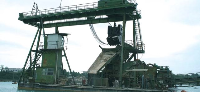
Type (N)TSCGECEWÖU MT SUB-E PLUS Submersible Cable
Enhanced Braided Earth Protection | 3.6/6 – 12/20 kV | 300m Depth Rating | DIN VDE 0250 Part 813
🛡️ Advanced Braided Earth Protection System
Enhanced electrical safety through continuous copper braided screen over each conductor
Superior electromagnetic shielding and mechanical protection for critical underwater applications
Certified Depth Performance
Permanent Water Immersion | 30 Bar Pressure | Salt & Brackish Water Certified
What is the Type (N)TSCGECEWÖU MT SUB-E PLUS Cable?
The Type (N)TSCGECEWÖU MT SUB-E PLUS represents an advanced evolution in submersible cable technology, featuring a specialized individual copper braid earth protection system that provides enhanced electrical safety and electromagnetic shielding for the most demanding underwater applications. The “-E” designation signifies the enhanced earth conductor configuration using continuous copper braiding rather than separate wire screens.
This premium submersible cable is engineered for permanent water immersion up to 300 meters depth under high mechanical stresses. The cable combines proven waterproofing technology with superior earth fault protection, making it the preferred choice for critical applications including submersible pumps, dredging machinery, floating dock infrastructure, and trailing operations in opencast mining where equipment reliability and personnel safety are paramount.
- Uniform current distribution during earth fault conditions
- Superior electromagnetic interference (EMI) shielding
- Enhanced mechanical protection against impact and abrasion
- Redundant current paths improving reliability
- Better heat dissipation from conductor to surrounding water
Key Application Environments:
Purpose and Specialized Applications
Enhanced Protection for Critical Installations
The MT SUB-E PLUS cable is specifically designed for applications where electrical safety and reliability cannot be compromised. The braided earth protection system provides superior performance in environments with high electrical noise, variable frequency drives (VFDs), or where equipment operates in electrically harsh conditions with potential for electromagnetic interference.
Primary Application Categories:
1. High-Power Submersible Pump Systems
- Mine Dewatering (>1MW Installations): Large submersible pumps operating continuously at depths up to 300m requiring superior EMI protection from VFD-induced electrical noise
- Municipal Water Supply: Critical infrastructure deep well pumps where failure is not acceptable – braided earth provides redundant protection
- Industrial Cooling Systems: High-capacity submerged pumps in power plants, steel mills, and petrochemical facilities
- Flood Control Stations: Emergency pumping installations requiring maximum reliability during crisis conditions
2. Dredging Operations
- Cutter Suction Dredgers: High-power cutting head motors (500kW+) generating significant electromagnetic fields – braided shielding prevents interference with control systems
- Trailing Suction Hopper Dredgers: Dynamic cable systems subject to constant motion where braided construction provides superior mechanical stability
- Clamshell and Grab Dredgers: Intermittent high-load operations where robust earth protection ensures personnel safety
- Jet Dredging Equipment: Water jetting systems in marine environments requiring enhanced corrosion resistance
3. Floating Dock and Marine Infrastructure
- Floating Dry Dock Ballast Systems: Multiple large submersible pumps operating in coordinated fashion – EMI shielding prevents cross-system interference
- Floating Production Platforms: Offshore oil and gas installations with stringent safety requirements
- Ship Repair Facilities: Submerged power distribution systems exposed to oils, chemicals, and mechanical stress
- Floating Storage Facilities: Long-term underwater cable installations requiring maximum service life
4. Opencast Mining Trailing Operations
- Dragline Excavators: Heavy-duty trailing cables (>600mm²) in wet pit conditions where water accumulation is constant
- Electric Rope Shovels: High-capacity mobile mining equipment operating in water-filled excavations
- Bucket-Wheel Excavators: Continuous mining operations where cable reliability directly impacts production
- Mobile Crushers: Primary crushing equipment in wet processing areas
Comparison: MT SUB-E PLUS vs. Standard MT SUB PLUS
Key Differences
| Feature | MT SUB PLUS (Standard) | MT SUB-E PLUS (Enhanced) |
|---|---|---|
| Earth Conductor Type | Tinned copper, Class 5 flexible, separate conductors | Bare copper individual braid over each phase |
| EMI Shielding Effectiveness | Standard (60-70dB) | Superior (>80dB at 1MHz) |
| Mechanical Protection | Good | Excellent – 360° braided armor |
| Maximum Tensile Load | 20 N/mm² | 15 N/mm² (optimized for braid integrity) |
| Best Applications | General submersible pumps, standard dredging | VFD-driven equipment, high-power systems, critical installations |
| Cost | Standard pricing | Premium pricing (15-20% higher) |
Advanced Technical Characteristics
Braided Earth Protection System Performance:
Continuous bare copper braided screen over each phase conductor providing uniform 360° protection and EMI shielding.
Proven waterproof performance under 30 bar hydrostatic pressure with dual EPR/CM sheath barrier system.
Shielding effectiveness >80dB at frequencies up to 1MHz, protecting against VFD-induced electrical noise.
Braided construction provides exceptional resistance to impact, abrasion, and mechanical stress in harsh underwater environments.
Certified for salt and brackish water immersion per HD 22.16 and AC internal testing standards.
Tinned copper stranded conductors (IEC 60228) maintain flexibility even with braided earth protection layer.
Electrical Performance Specifications:
| Voltage Rating (U₀/U) | Test Voltage | Max AC Operating Voltage | Current Rating Reference |
|---|---|---|---|
| 3.6/6 kV | 11 kV | 4.2/7.2 kV | VDE 0298 Part 4 |
| 6/10 kV | 17 kV | 6.9/12 kV | VDE 0298 Part 4 |
| 8.7/15 kV | 24 kV | 10.4/18 kV | VDE 0298 Part 4 |
| 12/20 kV | 29 kV | 13.9/24 kV | VDE 0298 Part 4 |
Thermal and Environmental Performance:
| Maximum Conductor Temperature (Continuous) | 90°C |
| Short Circuit Temperature (5 seconds) | 250°C |
| Maximum Water Temperature | 40°C |
| Ambient Temperature (Trailing Operation) | -25°C to +60°C |
| Ambient Temperature (Static Installation) | -40°C to +80°C |
| Maximum Immersion Depth | 300 meters (30 bar / 435 psi) |
Mechanical Performance:
- Maximum Tensile Load: 15 N/mm² of total phase conductor cross-section (based on conductor area, not cable weight)
- Minimum Bending Radius: Per VDE 0298 Part 3 – typically 20x cable outer diameter for trailing operations
- Braid Flexibility: Copper braid construction allows repeated bending without conductor breakage
- Abrasion Resistance: Dual sheath system protects braided earth layer from mechanical wear
Advanced Material Structure – Layer-by-Layer
1. Phase Conductors
| Material | Tinned copper wire (tin coating prevents oxidation) |
| Construction Class | Class 5 per VDE 0295 and IEC 60228 (highly flexible) |
| Available Cross Sections | 25 mm², 35 mm², 50 mm², 70 mm², 95 mm², 120 mm², 150 mm², 185 mm² |
| Temperature Rating | 90°C continuous, 250°C short circuit (5 seconds) |
2. Primary Insulation System
- Semiconductive Conductor Screen: Tape applied over tinned conductor eliminates air voids at conductor surface
- 3GI3 Quality EPR Insulation: Special grade Ethylene Propylene Rubber compound per VDE 0207 Part 20, optimized for underwater service with minimal water absorption
- Inner Semiconductive Layer: Extruded in single pass with insulation ensuring zero air gaps
- Outer Semiconductive Layer: Provides smooth interface for braided earth conductor contact
3. Protective Earth Conductors – Individual Copper Braid
| Material | Bare copper wire (no tin coating required for braid application) |
| Construction Type | Individual copper braid over each phase conductor |
| Braid Coverage | Typically 85-95% optical coverage providing continuous shield |
| Configuration | Three separate braided earth conductors (one per phase) |
| Function | Earth fault protection, EMI shielding, mechanical protection, heat dissipation |
How Braided Earth Protection Works:
The individual copper braid is woven over the outer semiconductive layer of each phase conductor, creating a flexible metallic screen. Key characteristics include:
- Uniform Current Distribution: During earth fault, current distributes evenly across all braid strands rather than concentrating in a single conductor
- Low Impedance Path: Multiple parallel copper strands create very low resistance/inductance earth path
- 360° EMI Shield: Continuous metallic coverage reflects electromagnetic fields preventing interference
- Mechanical Flexibility: Braided construction allows cable bending while maintaining electrical continuity
- Self-Healing Property: If individual braid wires break, redundant paths maintain protection
4. Central Filler
Rubber compound on textile polyester support, positioned at cable center. Functions:
- Maintains circular cable geometry
- Fills voids preventing water accumulation
- Provides mechanical cushioning
- Supports overall cable flexibility
5. Core Assembly
Three insulated and braided phase conductors are twisted together with optimal lay length. Semiconductive tape is wound over the twisted assembly creating additional water barrier and smooth surface for inner sheath application.
6. Inner Sheath – Primary Waterproof Barrier
| Material | Special EPR rubber compound, waterproofing grade GM1b per VDE 0207 Part 21 |
| Thickness | Per VDE 0250 Part 813 Table 2 (heavier than standard cables) |
| Water Absorption | <0.1% after 1000 hours immersion at 40°C |
| Function | Primary hermetic seal protecting conductor assembly from water ingress |
7. Outer Sheath – Ultimate Protection Layer
| Material | Special CM (Chloroprene-based) rubber compound, 5GM3 quality per VDE 0207 Part 21 |
| Thickness | Per VDE 0250 Part 813 Table 2 (extra-heavy duty) |
| Properties | Waterproofing, oil resistance, ozone resistance, abrasion resistance, marine organism resistance |
| Color | Black with identifying markings |
Compliance with International Standards
Primary Certification Standards:
Submersible Cable Testing Requirements:
| Standard | Test Requirement | MT SUB-E PLUS Performance |
|---|---|---|
| DIN VDE 0250-813 | Construction, dimensions, mechanical tests | Full compliance with braided earth construction |
| HD 22.16 | Permanent water immersion testing | Passes 1000+ hours at 300m equivalent pressure |
| AC Internal Test | Salt and brackish water resistance | Zero degradation in 3.5% NaCl solution |
| IEC 60228 | Conductor construction Class 5 | Tinned copper flexible stranded per specification |
| IEC 60332-1-2 | Flame retardant vertical test | Passes despite underwater application focus |
| IEC 60811-2-1 | Oil and ozone resistance | Type 2 oil resistance, superior ozone performance |
EMI/EMC Standards (Relevant for Braided Shielding):
- IEC 61000 Series: Electromagnetic Compatibility standards for electrical equipment and cables
- IEC 60364-4-44: Protection against electromagnetic disturbances in low-voltage installations
- IEEE 519: Recommended practice for harmonic control in electrical power systems
Safety Thresholds and Operating Limits
Critical Safety Parameters:
| Parameter | Specification | Safety Considerations |
|---|---|---|
| Maximum Immersion Depth | 300 meters (30 bar) | Exceeding depth can compromise braid integrity and force water through sheaths |
| Maximum Tensile Load | 15 N/mm² conductor area | Lower than standard cables to protect braided earth system integrity |
| Conductor Temperature | 90°C continuous | Braided earth provides enhanced heat dissipation to water |
| Water Temperature | 40°C maximum | Higher temperatures accelerate rubber compound aging |
| Minimum Bending Radius | 20x cable diameter (trailing) | Tight bending can damage braid structure |
| Short Circuit Temperature | 250°C (5 seconds) | Underwater faults can generate steam pressure – immediate shutdown required |
Braided Earth System Safety:
- Test braid continuity at each termination – resistance should be <0.5Ω per 100m
- Ensure braid is properly bonded at both cable ends during termination
- Never operate cable with damaged braid – even partial braid damage compromises protection
- Inspect braid integrity during underwater inspections – corrosion or breakage requires cable replacement
- Ground fault protection devices must be coordinated with braid impedance characteristics
Tensile Load Management:
The 15 N/mm² tensile limit requires careful installation planning:
- Calculate Total Weight: Include cable weight, pump/equipment weight, and dynamic forces from currents/waves
- Strain Relief Systems: Implement mechanical strain relief at pump heads and surface supports
- Support Intervals: For suspended installations, use intermediate supports every 50-100m depending on cable size
- Catenary Design: Properly design cable catenary to minimize stress at attachment points
- Dynamic Loading: Account for 50% safety margin for wave action and equipment movement
Ampacity Considerations with Braided Earth:
Installation Precautions and Best Practices
Braided Earth System Installation Requirements:
- Carefully strip outer sheath without cutting into copper braid strands
- Fold back braid strands evenly – do not twist or bunch
- Apply copper braid termination lug or clamp ensuring contact with all braid strands
- Torque termination hardware to manufacturer specification (typically 8-12 Nm for medium sizes)
- Apply corrosion protection compound to exposed braid/termination interface
- Install waterproof sealing system per termination kit instructions
- Test braid continuity with low-resistance ohmmeter before energization
Pre-Installation Testing:
- Insulation Resistance: Minimum 100 MΩ·km at 1000V DC for 1 minute – record baseline
- Braid Continuity: Each of three braids should measure <0.5Ω per 100m
- High Voltage Test: Apply 80% of factory test voltage for 1 minute
- Phase Conductor Continuity: Verify all conductors <1Ω per 100m
- Visual Inspection: Examine entire cable length for sheath damage
Mechanical Handling Precautions:
- Avoid Sharp Bends: Never bend cable tighter than 20x diameter – can break braid wires internally
- Controlled Deployment: Lower equipment at <1 meter/second to avoid shock loading
- Protect During Transport: Use protective sleeving when pulling through structures or around sharp edges
- Storage on Reels: Store on reels with diameter >30x cable diameter to prevent braid deformation
- Temperature Conditioning: Allow cable to reach ambient temperature before deployment
Operational Monitoring:
Essential Monitoring Systems:
- Insulation Monitoring Devices (IMD): Continuous monitoring of insulation resistance – critical for braided cables as braid shorts to phase indicate severe failure
- Ground Fault Detection: Sensitive ground fault relays set to 30mA maximum with 0.1s trip time
- Braid Continuity Monitoring: Some advanced installations use continuous braid resistance monitoring
- Thermal Monitoring: Fiber optic DTS (Distributed Temperature Sensing) for conductor temperature
Maintenance Schedule:
| Frequency | Inspection/Test | Acceptance Criteria |
|---|---|---|
| Daily | Visual inspection of accessible sections | No visible damage, discoloration, or water leakage |
| Weekly | Thermal imaging and termination inspection | No hot spots, terminations dry and secure |
| Monthly | Insulation resistance testing | >50 MΩ·km (degradation triggers investigation) |
| Quarterly | Braid continuity testing and underwater inspection | <0.5Ω per 100m, no visible braid damage |
| Annually | Comprehensive electrical testing including partial discharge | All parameters within 90% of commissioning values |
Common Problems and Troubleshooting
Braided Earth System Specific Issues:
1. Braid Corrosion and Deterioration
Symptoms: Increasing braid resistance, intermittent earth faults, or visible corrosion at termination points.
Causes:
- Galvanic corrosion between bare copper braid and dissimilar metals at terminations
- Saltwater exposure accelerating copper oxidation in damaged sheath areas
- Stray currents causing electrochemical deterioration of braid strands
- Insufficient corrosion protection at termination interfaces
Prevention and Solutions:
- Apply zinc-rich corrosion protection compound at all braid terminations
- Use copper or tin-plated brass termination hardware only – avoid aluminum or steel
- Implement cathodic protection systems for large installations
- Quarterly inspection of braid resistance – replace cable if >1Ω per 100m
- Ensure proper grounding system design eliminates stray current paths
2. Braid Mechanical Damage
Symptoms: High braid resistance, loss of EMI shielding effectiveness, or intermittent earth protection.
Causes:
- Over-bending during installation breaking individual braid wires
- Excessive tensile load causing braid elongation and wire fracture
- Abrasion wearing through outer sheath exposing braid to mechanical damage
- Impact from dropped objects or equipment collision
Solutions:
- Implement strict bending radius controls during installation
- Install mechanical strain relief to keep tensile loads <15 N/mm²
- Use protective sleeving in high-abrasion areas
- Establish exclusion zones preventing equipment from contacting cable
- Replace cables with significant braid damage – field repair not recommended
3. Electromagnetic Interference Despite Braided Shielding
Symptoms: Control system malfunctions, instrumentation noise, or communications interference near cable routes.
Causes:
- Incomplete braid bonding at one or both cable ends reducing shield effectiveness
- Braid discontinuity from corrosion or mechanical damage
- Ground loops formed by multiple bonding points at incorrect locations
- Very high harmonic content exceeding braid shielding capacity (rare)
Solutions:
- Verify braid is bonded at equipment end, isolated or bonded through high-frequency bypass at source end depending on system design
- Test braid continuity and repair/replace if compromised
- Install harmonic filters on VFD equipment if total harmonic distortion (THD) >5%
- Route sensitive control cables away from power cables (minimum 300mm separation)
4. Tensile Load Exceedance
Symptoms: Cable elongation, visible deformation, increased braid resistance, or catastrophic conductor failure.
Root Causes:
- Underestimated total installation weight during design
- Failure to account for dynamic forces from waves, currents, or equipment movement
- Inadequate strain relief systems
- Equipment sinking deeper than planned depth
Prevention:
- Conduct thorough load calculations including 50% dynamic safety factor
- Install load monitoring systems on critical installations
- Implement mechanical strain relief and support systems
- Use intermediate supports for long suspended sections
- Establish automatic shutdown if tension exceeds safe limits
5. Water Ingress (Same as Standard Submersible Cables)
Note: Braided earth construction does not change waterproofing performance – inner and outer sheaths provide water barrier. Follow same diagnosis and prevention procedures as standard submersible cables.
6. VFD-Induced Bearing Currents
Symptoms: Premature bearing failure in submersible motors despite proper cable installation.
Cause:
- High-frequency common-mode voltages from VFDs inducing currents through motor bearings
- While braided cables provide excellent shielding, some high-frequency energy can still capacitively couple to motor frame
Solutions:
- Install VFD output reactors or filters to reduce dV/dt (voltage rise time)
- Use insulated motor bearings on drive end if bearing failures persist
- Ensure proper motor frame grounding through braided earth system
- Consider shaft grounding rings for large motors (>100kW)
- On-site underwater cable inspection and testing services
- EMI/EMC evaluation and mitigation recommendations
- Failure analysis laboratory with braid integrity testing
- Custom cable design for unique high-EMI environments
- Training programs for installation and maintenance teams
- 24/7 emergency support for critical installations
Complete Technical Specifications
Available Configurations (6/10 kV Example):
| Conductor Size | Min Diameter | Max Diameter | Approx. Weight | Max Tensile Load |
|---|---|---|---|---|
| 3×25 + 3×25/3E | 43.4 mm | 45.7 mm | 2870 kg/km | 1125 N |
| 3×35 + 3×25/3E | 45.0 mm | 47.3 mm | 3220 kg/km | 1575 N |
| 3×50 + 3×25/3E | 48.1 mm | 50.4 mm | 3870 kg/km | 2250 N |
| 3×70 + 3×35/3E | 53.7 mm | 56.1 mm | 5000 kg/km | 3150 N |
| 3×95 + 3×50/3E | 58.4 mm | 60.8 mm | 6210 kg/km | 4275 N |
| 3×120 + 3×70/3E | 62.9 mm | 65.9 mm | 7580 kg/km | 5400 N |
| 3×150 + 3×70/3E | 69.3 mm | 72.4 mm | 9090 kg/km | 6750 N |
| 3×185 + 3×95/3E | 72.1 mm | 75.2 mm | 10390 kg/km | 8325 N |
Note: Configurations available for all voltage ratings (3.6/6 kV, 6/10 kV, 8.7/15 kV, 12/20 kV). Cables typically supplied on steel reels. Custom lengths available up to 2000m on special reels.
Premium Submersible Cable Solutions
Anhui Feichun Special Cable Co., Ltd. – Specialists in advanced braided earth protection submersible cables for critical mining and marine applications worldwide.
Technical Engineering
Braided cable design, EMI/EMC evaluation, failure analysis, custom specifications
International Direct
+86 13855123218
24/7 emergency support, urgent cable supply, technical assistance
Technical Resources and Standards
Standards Organizations:
- VDE Institute – German electrical standards, DIN VDE specifications
- International Electrotechnical Commission – Global electrical standards including EMC
- IEEE Xplore – Technical papers on cable shielding and EMI mitigation
- CENELEC – European electrical standardization
Feichun Cable Global Network:
- Australian Mining Cables – AS/NZS compliant submersible cables for Australia and Pacific
- Reeling Cables – Complete range for mobile mining and port equipment
- Crane and Festoon Cables – Specialized cables for port machinery
- Cables Mineros Latinoamérica – Soluciones para minería submarina
- 飛純電纜(繁體中文) – 編織接地潛水電纜專家


