FEICHUN CABLE
Anhui Feichun Special Cable Co., Ltd. (安徽飞纯特种电缆有限公司)
What is SHD-GC 2/0 AWG 2 kV Cable? Complete Technical Guide
Quick Overview: The SHD-GC 2/0 AWG 2 kV cable is a heavy-duty, MSHA-approved portable power cable specifically engineered for extreme mining and tunneling environments. Featuring EPR insulation and TPU jacketing, this cable delivers reliable power transmission for draglines, shovels, dredges, and mobile mining equipment in the harshest conditions.
MSHA Approved Mining Grade -40°C Rated 2 kV
1. What is SHD-GC Cable?
SHD-GC (Shielded Heavy Duty – Ground Check) cable represents the pinnacle of portable power cable engineering for mining applications. The designation breaks down as follows:
- SH – Shielded design with composite tinned copper/polyamide braid for electrical safety
- D – Heavy Duty construction with extra thick TPU jacketing
- GC – Ground Check conductor for continuous ground integrity monitoring
The 2/0 AWG specification refers to the American Wire Gauge standard, indicating a conductor with 342 strands (19×18 configuration) providing exceptional flexibility and current-carrying capacity. The 2 kV voltage rating ensures safe operation in medium-voltage mining distribution systems.
2. Primary Purpose and Applications
The SHD-GC 2/0 AWG 2 kV cable is purpose-built for the most demanding mobile mining equipment applications:
Primary Applications
🏗️ Dragline Systems
Large excavation equipment requiring continuous high-amperage power with extreme flexibility during operation
⛏️ Power Shovels
Heavy-duty excavators demanding reliable power transmission through repeated bending cycles
🚢 Dredging Equipment
Marine and waterway excavation systems requiring moisture-resistant, abrasion-proof cabling
🔨 Drilling Rigs
Rotary and percussion drills needing impact-resistant power delivery in underground environments
Why This Cable for Mining?
Mining operations face unique challenges that standard industrial cables cannot withstand. The SHD-GC cable addresses these through:
- Continuous ground monitoring – The dedicated 8 AWG ground check conductor provides real-time ground fault detection
- Extreme mobility – Designed for equipment that moves thousands of times per shift
- Harsh environment tolerance – Resists coal dust, mineral oils, extreme temperatures, and physical abuse
- Safety compliance – MSHA approval ensures it meets the strictest underground mining safety standards
3. Key Characteristics and Performance Features
Mechanical Properties
- Exceptional Flexibility – 342-strand conductor construction (19×18) allows tight bending radius of just 8× cable diameter, critical for coiled cable reels on mobile equipment
- Superior Abrasion Resistance – Extra heavy-duty TPU outer jacket with integral filler compound withstands continuous dragging across rough mine floors and over equipment
- Impact Protection – Multi-layer construction absorbs mechanical shocks from falling rocks and equipment impacts
- Tensile Strength – Rated for 3000N maximum pulling force without damage to internal conductors
Electrical Performance
| Parameter | Specification | Significance |
|---|---|---|
| Ampacity | 243A @ 40°C | Continuous current capacity for sustained operation |
| Voltage Rating | 2000V (2kV) | Maximum operating voltage between conductors |
| Conductor Resistance | 0.0868 Ω/1000 ft @ 25°C | Low resistance minimizes power loss and heating |
| Inductance | 0.092 mH/1000 ft | Optimized for AC power distribution |
| Capacitance | 0.16 μF/1000 ft | Low capacitance reduces reactive losses |
| Short-Circuit Current | 9.64 kA | Fault current capacity (90°C to 250°C) |
Environmental Resistance
- Temperature Range – Rated and flexible from -40°C to +90°C conductor temperature, covering extreme Arctic to desert mining conditions
- Ozone & Weather Resistance – EPR insulation remains stable under UV exposure and atmospheric ozone
- Flame Resistance – Meets FT1 and FT5 flame test requirements for underground mining
- Oil & Chemical Resistance – TPU jacket resists hydraulic oils, diesel fuel, and mineral-based lubricants
- Moisture Resistance – Sealed construction prevents water ingress in wet mine conditions
4. Material Structure and Construction
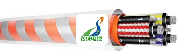
The SHD-GC cable employs a sophisticated multi-layer design where each component serves critical safety and performance functions:
Layer-by-Layer Breakdown
Layer 1: Power Conductors (×3)
Material: Annealed flexible stranded tin-coated copper
Construction: 342 strands in 19×18 configuration
Size: 2/0 AWG
Standard: ASTM B172, ICEA S-75-381 Table 3-22
Function: Tin coating prevents oxidation and improves conductivity in humid mining environments. Ultra-flexible stranding withstands millions of flex cycles.
Layer 2: Conductor Shield
Material: Semi-conductive layer
Function: Creates uniform electric field distribution around conductor, preventing corona discharge and voltage stress concentrations that lead to insulation breakdown.
Layer 3: Primary Insulation
Material: Ethylene-Propylene Rubber (EPR)
Thickness: 0.080 inches (2.03 mm)
Function: EPR provides superior flexibility at low temperatures, excellent dielectric properties, and resistance to thermal aging compared to PVC or XLPE alternatives.
Layer 4: Insulation Shield
Material: Non-conducting bedding tape + composite tinned copper/polyamide braid
Coverage: Minimum 60%
Function: The braided shield provides electrical grounding, mechanical protection, and electromagnetic interference (EMI) protection. The polyamide component serves as circuit identification through color coding (black, white, red).
Layer 5: Grounding Conductors (×2)
Material: Annealed tin-coated copper, non-insulated
Size: Per ICEA S-75-381 Table 3-25
Function: Dual grounding conductors provide equipment grounding and fault current return path with redundancy for safety.
Layer 6: Ground Check Conductor
Material: Tinned copper with yellow polypropylene insulation
Size: 8 AWG
Function: Continuous ground integrity monitoring. This pilot wire allows ground fault detection systems to verify the grounding system remains intact during operation.
Layer 7: Assembly Configuration
Construction: Three power conductors + ground check + two grounding conductors cabled together in round configuration
Function: Round assembly provides uniform flexibility in all bending directions and balanced mechanical properties.
Layer 8: Core Separator
Material: Single-faced rubber-filled binder tape
Function: Maintains conductor spacing, provides cushioning during flexing, and prevents conductor abrasion.
Layer 9: Outer Jacket
Material: Extra heavy-duty, integral-filled Thermoplastic Polyurethane (TPU)
Thickness: 0.205 inches (5.2 mm)
Color: Transparent with orange/silver reflective tape beneath
Standard: ICEA S-75-381 Table 3-3
Function: TPU provides unmatched abrasion resistance (far superior to rubber or PVC), excellent low-temperature flexibility, and resistance to oils and chemicals. The reflective tape enhances visibility in low-light underground environments, critical for safety.
Physical Specifications
- Overall Diameter: 2.00 inches (-5% / +8% tolerance)
- Weight: 2,933 lbs/1,000 ft (4,365 kg/km)
- Minimum Bending Radius: 16 inches (8× overall diameter)
- Standard Packaging: 500m reels on heavy-duty drums
5. Compliance with Standards and Certifications
The SHD-GC 2/0 AWG 2 kV cable meets or exceeds the following industry standards, ensuring it is legally compliant for underground mining operations worldwide:
Primary Standards
| Standard | Title | Scope |
|---|---|---|
| ICEA S-75-381 | Portable and Power Feeder Cables for Use in Mines | Defines construction, materials, testing, and performance requirements for mining cables. This is the foundational standard for all specifications. |
| NEMA WC-58 | Portable and Power Feeder Cables for Use in Mines | Equivalent to ICEA S-75-381, published by National Electrical Manufacturers Association for manufacturing conformity. |
| ASTM B172 | Rope-Lay-Stranded Copper Conductors | Specifies copper conductor stranding, ensuring proper flexibility and electrical properties. |
| MSHA | Mine Safety and Health Administration | Federal approval required for use in US mines. Approval No.: P-07-KA030001 |
Safety and Testing Standards
- FT1 Flame Test – Vertical flame test per CSA C22.2 requirements ensuring limited flame propagation
- FT5 Flame Test – Severe vertical flame test demonstrating self-extinguishing properties
- 90°C Continuous Rating – Conductor temperature rating ensures safe operation under continuous full load
- 250°C Short-Circuit Rating – Cable withstands fault currents up to 9.64 kA with conductor temperature rise to 250°C
Manufacturing Quality
Each cable is indent-printed with the following legend for traceability:
FEICHUN CABLE 3 (VOLTAGE)(SIZE) TYPE SHD-GC FT1 FT5+90°C MSHA:P-07-KA030001This permanent marking ensures compliance verification throughout the cable’s service life and provides critical information for maintenance personnel.
6. Safety Thresholds and Operating Limits
⚠️ Critical Operating Parameters
Exceeding these thresholds may result in equipment failure, fire hazard, or personnel injury. Always consult with FEICHUN technical support when approaching operational limits.
Electrical Safety Limits
| Parameter | Maximum Value | Consequences of Exceeding |
|---|---|---|
| Continuous Current | 243A @ 40°C ambient | Excessive heating leads to insulation degradation and eventual breakdown |
| Operating Voltage | 2000V (line-to-line) | Corona discharge, tracking, and potential flashover to ground |
| Short-Circuit Current | 9.64 kA | Conductor melting and catastrophic cable failure |
| Conductor Temperature | 90°C continuous 250°C short-circuit | Permanent insulation damage and reduced service life |
Mechanical Safety Limits
- Maximum Tensile Force: 3000N – Exceeding causes conductor breakage and shield damage
- Minimum Bending Radius: 16 inches (8× diameter) – Tighter bending causes kinking and internal damage
- Coiling Radius: Never coil tighter than 8× diameter to prevent compression damage to inner conductors
- Drop Impact: Avoid dropping heavy objects on cable; impact damage may not be visible but can compromise internal structure
Environmental Operating Range
- Temperature: -40°C to +90°C – Cable becomes brittle below -40°C and insulation softens above 90°C
- Humidity: Designed for 100% humidity, but ensure terminations are properly sealed
- Submersion: Not rated for continuous submersion; temporary water exposure acceptable but drain and dry promptly
- Chemical Exposure: Resistant to mineral oils and common mining chemicals; avoid prolonged contact with strong acids or solvents
7. Precautions for Use and Installation
Before Installation
- Inspect Upon Receipt: Check for shipping damage, verify cable marking matches order specifications, and confirm continuity of all conductors including ground check
- Storage Requirements: Store horizontally on reels in dry location, protected from direct sunlight. Temperature range: -10°C to +40°C
- Uncoiling Procedure: Always uncoil by rolling drum or using rotating cable reel. Never pull cable off stationary drum as this introduces twists and kinks
- Handling: Use cable grips or proper slings when lifting. Never drag cable by bare hands over sharp edges
During Installation
- Route Planning: Plan cable routing to minimize bending, avoid sharp edges, and maintain clearance from hot surfaces (minimum 1 meter from equipment exhausts)
- Pulling Tension: Use mechanical pulling equipment with tension monitoring. Maximum pull: 3000N. Apply pulling force to conductors through proper cable grips, never to the jacket
- Termination:
- Strip jacket using proper cable stripping tools – avoid knife cuts that nick conductors
- Maintain shield continuity through 360° connection to equipment ground
- Terminate ground check conductor to monitoring system
- Use heat-shrink boots or split boots rated for 2kV to seal terminations
- Phase identification: Follow color coding in braid – black, white, red
- Ground Check System: Connect yellow ground check conductor to continuous monitoring relay. Test ground continuity before energizing circuit
- Support and Protection:
- Support cable every 3 meters when suspended
- Use cable trays or festoon systems for moving equipment
- Install protective conduit where cable crosses traffic areas
- Maintain minimum 8× diameter bend radius at all support points
During Operation
- Daily Visual Inspection: Check for jacket cuts, abrasions, bulges, or flattening. Inspect terminations for heat discoloration or tracking marks
- Ground Check Monitoring: Verify ground monitoring system is active. Investigate immediately if ground fault alarm activates
- Temperature Monitoring: For high-load applications, use infrared thermography monthly to detect hot spots indicating connection issues
- Movement Monitoring: On mobile equipment, inspect cable routing monthly to ensure no excessive bending or abrasion developing
- Load Management: Do not exceed 243A continuous current. If equipment draws higher current, consult FEICHUN for proper cable sizing
Maintenance Schedule
| Frequency | Inspection Item | Action Required |
|---|---|---|
| Daily | Visual inspection | Check for obvious damage, verify ground check system functioning |
| Weekly | Termination inspection | Tighten connections, check for overheating signs |
| Monthly | Insulation resistance test | Megger test at 1000V DC, minimum 1000 MΩ |
| Quarterly | Physical examination | Uncoil and inspect entire length for internal damage |
| Annually | Full electrical testing | Dielectric strength, conductor resistance, ground continuity |
Critical Safety Warnings
- De-energize Before Handling: Always disconnect power and verify zero energy state before moving, inspecting, or maintaining cable
- Ground Check Integrity: Never bypass or disable ground check monitoring system. This is your primary safety protection
- Damaged Cable Removal: Any cable with visible conductor exposure, severe jacket damage, or failed insulation test must be removed from service immediately
- Qualified Personnel Only: Installation and maintenance must be performed by qualified electricians familiar with medium-voltage systems
- MSHA Compliance: Maintain all required records and test documentation as mandated by mining safety regulations
8. Common Problems and Troubleshooting
Problem 1: Premature Jacket Wear
Symptoms: Abrasion through TPU jacket exposing underlying layers, particularly at drag points or cable coils
Causes:
- Excessive dragging over rough surfaces
- Contamination with aggressive chemicals or sharp particles
- Improper storage allowing cable to sit on sharp objects
Solutions:
- Install cable protectors or sleeves at high-wear zones
- Use cable trays or festoon systems to minimize ground contact
- Regular cleaning to remove abrasive contamination
- Replace worn sections before conductor exposure occurs
Problem 2: Ground Check Alarm Activation
Symptoms: Ground fault monitoring system indicates loss of ground continuity
Causes:
- Broken ground check conductor due to excessive flexing
- Corroded connections at terminations
- Water ingress causing intermittent ground faults
- Physical damage to ground conductors
Solutions:
- Immediately de-energize and lock out equipment
- Inspect full cable length for damage
- Test ground continuity using low-resistance ohmmeter
- If ground check conductor is broken, cable must be replaced or re-terminated at damage point
- Verify all terminations are dry and properly sealed
Problem 3: Overheating at Connections
Symptoms: Discoloration, melting, or burning smell at cable terminations or splices
Causes:
- Loose connections creating high resistance
- Undersized lugs or improper crimping
- Corrosion at connection interfaces
- Current overload
Solutions:
- De-energize and cool system completely
- Inspect and re-torque all connections to manufacturer specifications
- Replace any discolored or damaged components
- Verify current draw does not exceed 243A rating
- Use anti-oxidant compound on copper connections
- Consider upgrading to larger cable if load consistently approaches rating
Problem 4: Cable Kinking or Permanent Deformation
Symptoms: Visible bends, flattened sections, or cable that won’t straighten
Causes:
- Bending radius below 16-inch minimum
- Coiling under tension
- Heavy objects placed on cable
- Improper uncoiling technique
Solutions:
- Conduct insulation resistance test on affected section
- If insulation passes test and damage is minor, cable may continue in service with increased monitoring
- Severe kinks or flat spots require cable replacement
- Implement proper cable handling training for operators
- Use cable saddles or larger drums to maintain bend radius
Problem 5: Insulation Failure / Tripping of Protection Devices
Symptoms: Ground fault relays tripping, circuit breakers opening, visible tracking on cable surface
Causes:
- Water ingress through jacket damage
- Thermal aging from prolonged overload
- Mechanical damage creating internal shorts
- Corona discharge from contaminated surfaces
Solutions:
- Perform insulation resistance test (megger at 1000V DC)
- If reading below 1000 MΩ, cable has compromised insulation
- Isolate fault location using time-domain reflectometry (TDR) if available
- Cut and re-terminate if fault is near end; otherwise replace cable
- Clean and dry all components before re-energizing
- Never operate cable with known insulation defects
Problem 6: Cold Weather Stiffness
Symptoms: Difficulty coiling or uncoiling cable, reduced flexibility in temperatures below -20°C
Causes:
- Normal material behavior at extreme low temperatures
- Jacket compound can become stiffer though remains functional to -40°C
Solutions:
- Allow cable to warm gradually before flexing when possible
- Use heated storage areas for cable reels in Arctic conditions
- Minimize bending cycles in extreme cold
- Increase bending radius by 20% when ambient is below -30°C
- Cable will regain full flexibility when returned to normal temperatures
Problem 7: Shield Braid Damage
Symptoms: Visible copper strands of shield braid, especially after jacket abrasion
Causes:
- Progressive jacket wear exposing braid
- Improper handling during installation
- Chemical attack on polyamide component
Solutions:
- If less than 20% of braid is damaged and primary insulation intact, apply heavy-duty repair tape as temporary measure
- Schedule cable replacement at next maintenance window
- Extensive braid damage (over 30%) requires immediate replacement as EMI protection and ground path are compromised
- Never operate with exposed primary insulation
Preventive Measures Summary
- Implement comprehensive operator training on cable handling
- Establish regular inspection and testing schedules
- Maintain detailed service logs documenting all inspections and repairs
- Stock critical spare parts including lugs, boots, and repair materials
- Consider cable management system improvements (trays, festoons) to reduce mechanical stress
- Work with FEICHUN technical support for ongoing optimization of cable performance
Need Technical Support?
Our engineering team is ready to assist with cable selection, installation guidance, troubleshooting, and custom solutions for your specific mining application.
Contact Our Engineers📞 +86 138 55123218 | ✉ [email protected]
Conclusion
The FEICHUN SHD-GC 2/0 AWG 2 kV cable represents decades of cable engineering evolution specifically tailored to mining industry demands. Its multi-layer construction, MSHA certification, and proven field performance make it the preferred choice for mobile mining equipment worldwide.
Key advantages include:
- Continuous ground monitoring via dedicated ground check conductor
- Superior mechanical durability through extra-heavy TPU jacketing
- Exceptional flexibility enabling tight coiling on cable reels
- Wide temperature range covering global mining climates
- Compliance with strictest safety standards (MSHA, ICEA, NEMA)
By understanding the cable’s construction, respecting operating limits, following proper installation procedures, and maintaining regular inspection schedules, mining operations can maximize cable service life while ensuring worker safety and minimizing downtime.
Custom Cable Solutions Available
FEICHUN Cable offers custom configurations of the SHD-GC series to meet specific application requirements including:
- Alternative conductor sizes (1/0 AWG to 500 MCM)
- Different voltage ratings (600V to 5kV)
- Extended length reels
- Special jacket colors for identification
- Additional grounding conductors
- Custom printing for company branding
Contact our technical sales team to discuss your specific requirements.