
Comprehensive Technical Guide to SRPS-Compliant Electrical Cables for Mining and Industrial Applications
What is Serbian Cable Standards (SRPS) Cable?
Comprehensive Technical Guide to SRPS-Compliant Electrical Cables for Mining and Industrial Applications
About Anhui Feichun Special Cable Co., Ltd. (安徽飞纯特种电缆有限公司)
Anhui Feichun Special Cable Co., Ltd. is a leading manufacturer of high-quality SRPS-compliant cables for mining, industrial, and specialized applications. With advanced manufacturing facilities and rigorous quality control systems, we provide cables that meet international standards including SRPS, IEC, and AS/NZS certifications.
Table of Contents
1. Introduction to SRPS Cable Standards
Serbian Power Engineering Standards (SRPS) represent a comprehensive framework of technical regulations governing electrical cables and conductors in Serbia and other regions that have adopted these specifications. SRPS standards are developed and maintained by the Institute for Standardization of Serbia (ISS), which operates as the national standardization body responsible for developing, publishing, and promoting technical standards across various industries.
The SRPS system has undergone significant harmonization with European standards, with over 97 percent of standards transferred to the Serbian system according to official regulatory documentation.[1] This harmonization ensures that SRPS-compliant cables meet both regional requirements and international safety benchmarks, making them suitable for global trade and cross-border industrial applications.
Key Definition
SRPS Cable refers to electrical cables manufactured according to Serbian Power Engineering Standards, which encompass design specifications, material requirements, testing protocols, and safety parameters for various types of power cables, control cables, and specialized industrial cables including mining applications.
SRPS standards cover an extensive range of cable types, from low-voltage installation conductors to high-voltage power cables rated up to 60 kV. According to the Institute for Standardization of Serbia, SRPS EN IEC 60228:2024 specifies nominal cross-sectional areas ranging from 0.5 mm² to 3,500 mm² for conductors in electric power cables.[2] This wide range enables SRPS cables to serve diverse applications across mining operations, industrial facilities, and power distribution networks.
2. Purpose and Application Scope
2.1 Primary Purpose
SRPS cable standards serve multiple critical purposes in the electrical and mining industries. The primary objectives include establishing uniform specifications for cable construction, ensuring consistent electrical performance across different manufacturers, defining safety requirements to protect personnel and equipment, and providing clear testing methodologies for quality assurance.
The standards are particularly crucial for mining operations, where cables must withstand harsh environmental conditions. SRPS N.C5.374:2005 specifically addresses heavy-duty flexible mining cables for surface mining applications with rubber insulation and sheath, rated for voltages from 3.6/6 kV up to 20/35 kV. These specifications ensure that cables can handle the demanding requirements of mobile machinery in mining operations, including continuous flexing, mechanical stress, and exposure to moisture and chemicals.
2.2 Application Sectors
Mining Industry
Underground and surface mining operations requiring robust cables for continuous mining machines, shuttle cars, roof bolting machines, and conveyor systems. Compatible with equipment used in Australian mining operations adhering to AS/NZS standards.
Power Distribution
Fixed installation cables for power transmission networks rated from 1 kV to 35 kV, including underground distribution systems and overhead line applications.
Industrial Facilities
Manufacturing plants, processing facilities, and heavy industrial operations requiring cables that comply with SRPS EN 50525 series specifications for various voltage ratings.
Marine and Port Equipment
Specialized applications in port terminals and shipyards where cables must resist saltwater corrosion and operate reliably in harsh marine environments.
2.3 Voltage Rating Categories
| Voltage Category | Rated Voltage (U₀/U) | Typical Applications | Relevant SRPS Standards |
|---|---|---|---|
| Low Voltage | 450/750 V | Installation conductors, control cables, lighting circuits | SRPS EN 50525-2-21, SRPS N.C3.320 |
| Low Voltage | 0.6/1 kV | Mining cables, industrial power distribution, motor connections | SRPS N.C5.353, SRPS N.C5.360 |
| Medium Voltage | 3.6/6 kV | Mining equipment, industrial feeders, distribution networks | SRPS N.C5.364, SRPS N.C5.374 |
| Medium Voltage | 6/10 kV | Power distribution, industrial substations | SRPS N.C5.220, SRPS N.C5.225 |
| Medium Voltage | 10/20/35 kV | High-power mining equipment, transmission lines | SRPS N.C5.231, SRPS N.C5.374 |
| High Voltage | Up to 60 kV | Major transmission networks, heavy industrial facilities | SRPS N.C5.020, SRPS N.C5.025 |
3. Technical Characteristics
3.1 Electrical Performance Parameters
SRPS cables must meet stringent electrical performance criteria as defined by harmonized standards. According to IEC 60228, which forms the basis for SRPS EN IEC 60228:2024, conductor resistance values are precisely specified to ensure consistent electrical performance.[3] The standard defines maximum DC resistance at 20°C for various conductor sizes, ensuring efficient power transmission and minimal energy loss.
| Nominal Cross-Section (mm²) | Max DC Resistance at 20°C (Ω/km) – Class 2 Copper | Current Carrying Capacity (A)* | Typical Application |
|---|---|---|---|
| 1.5 | 12.1 | 17.5 | Control circuits, signaling |
| 2.5 | 7.41 | 24 | Lighting circuits, small motors |
| 4 | 4.61 | 32 | Power distribution, machinery |
| 6 | 3.08 | 41 | Mining equipment, industrial loads |
| 10 | 1.83 | 57 | Heavy machinery, submersible pumps |
| 16 | 1.15 | 76 | Mining trailing cables, industrial feeders |
| 25 | 0.727 | 101 | Main distribution, high-power equipment |
| 35 | 0.524 | 125 | Heavy mining equipment, transformers |
| 50 | 0.387 | 151 | High-capacity mining machines |
| 70 | 0.268 | 192 | Major mining installations |
| 95 | 0.193 | 232 | Continuous mining machines, draglines |
| 120 | 0.153 | 269 | High-voltage mining equipment |
*Current carrying capacity values are approximate and vary based on installation method, ambient temperature, and cable construction. Values shown for single-core cables in air at 30°C ambient temperature.
3.2 Mechanical Performance Characteristics
SRPS mining cables must withstand significant mechanical stress during operation. The standards specify minimum requirements for tensile strength, flex life, abrasion resistance, and crush resistance. For mining applications, SRPS N.C5.374:2005 establishes that heavy-duty flexible mining cables must endure continuous movement, repeated bending cycles exceeding 10,000 flexures, and impact resistance suitable for harsh underground environments.
Tensile Strength
Copper Conductors: ≥300 N/mm²
Aluminum Conductors: ≥160 N/mm²
Ensures cables maintain structural integrity under mechanical stress during installation and operation.
Bending Radius
Fixed Installation: ≥6× cable diameter
Flexible/Mining Cables: ≥10× cable diameter
Critical for preventing conductor damage and insulation failure during cable routing.
Flex Life Expectancy
Class 5 Conductors: 10,000-30,000 cycles
Mining Cables: >50,000 cycles
Defines durability under repetitive motion typical in mobile mining equipment.
Temperature Ratings
PVC Insulation: 70°C continuous
XLPE Insulation: 90°C continuous
EPR Insulation: 90°C continuous
Rubber (Type G): 110°C continuous
3.3 Environmental Resistance Properties
SRPS standards mandate specific resistance characteristics for cables operating in challenging environments. According to SRPS N.C0.190:1991, heat-resistant elastomeric insulations and protective layers must withstand exposure to oils, chemicals, moisture, and temperature extremes commonly encountered in mining and industrial settings.
| Property | Test Standard | Requirement | Application Relevance |
|---|---|---|---|
| Water Resistance | IEC 60332 | No water penetration after immersion | Underground mining, wet environments |
| Oil Resistance | SRPS N.C0.057 | No degradation after 168h exposure | Industrial facilities, machinery |
| Abrasion Resistance | SRPS N.C0.050 | ≥1000 cycles without jacket failure | Mining trailing cables, mobile equipment |
| Flame Resistance | SRPS EN IEC 60332-3-22 | Self-extinguishing within 60 seconds | Underground mines, confined spaces |
| UV Resistance | IEC 60811 | ≥85% tensile strength retention | Outdoor installations, surface mining |
| Chemical Resistance | SRPS N.C0.190 | No cracking or swelling | Chemical plants, mining operations |
The flame propagation test specified in SRPS EN IEC 60332-3-22:2019 requires cables to pass Category A testing, where bunched cables with a nominal total volume of non-metallic material of 7 l/m are subjected to flame application for 40 minutes.[4] This rigorous testing ensures cables do not contribute to fire spread in underground mining environments.
4. Material Structure and Construction
4.1 Conductor Configuration
SRPS standards recognize multiple conductor classifications based on flexibility requirements and application demands. According to IEC 60228, which is harmonized with SRPS EN IEC 60228:2024, conductors are classified into distinct categories: Class 1 (solid conductors for fixed installations), Class 2 (stranded conductors for fixed installations), and Classes 5 and 6 (flexible conductors for mobile equipment and mining applications).[5]
| Conductor Class | Construction | Flexibility Level | Primary Applications |
|---|---|---|---|
| Class 1 | Single solid wire | Rigid | Fixed building wiring, permanent installations |
| Class 2 | 7-61 stranded wires | Semi-flexible | Fixed power cables, distribution networks |
| Class 5 | Multiple fine strands | Flexible | Portable equipment, control cables, standard mining applications |
| Class 6 | Extra-fine multiple strands | Extra flexible | Heavy-duty mining trailing cables, continuous flexing applications |
4.2 Insulation Systems
SRPS standards specify various insulation materials tailored to specific operating conditions and voltage ratings. The selection of insulation material significantly impacts cable performance, safety, and longevity. SRPS N.C0.190:1991 and SRPS N.C0.195:1990 provide detailed specifications for thermoplastic and heat-resistant insulations used in power cables.
PVC (Polyvinyl Chloride) Insulation
PVC compounds specified in SRPS N.C3.203:1972 and related standards offer excellent electrical properties, good chemical resistance, and cost-effectiveness. Standard PVC insulation is rated for continuous operation at 70°C with a short-circuit temperature limit of 160°C. PVC-insulated cables are commonly used in fixed installations where flexibility is not critical, including building wiring, control circuits, and stationary equipment connections.
PVC Compound Specifications (SRPS Standards)
Type P/J: Standard PVC compound for general-purpose installation conductors with reinforced insulation
Type P/MJ: PVC compound for multi-stranded conductors requiring increased flexibility
Type P/FJ: Fine-stranded conductors with PVC insulation for applications requiring frequent bending
XLPE (Cross-Linked Polyethylene) Insulation
Cross-linked polyethylene provides superior thermal performance with continuous operating temperatures up to 90°C and short-circuit ratings of 250°C. SRPS N.C5.230:1988 and SRPS N.C5.235:1988 govern cables with XLPE insulation for rated voltages from 1 kV to 35 kV. XLPE insulation offers excellent electrical properties, superior moisture resistance compared to PVC, and enhanced mechanical strength at elevated temperatures.
EPR (Ethylene Propylene Rubber) Insulation
Ethylene-propylene rubber insulation provides exceptional flexibility and heat resistance, making it ideal for mining applications. SRPS N.C5.353:1994 specifies EPR insulation for mining cables rated 0.6/1 kV. EPR exhibits excellent resistance to ozone, weathering, and chemical exposure, maintains flexibility at low temperatures down to -40°C, and offers superior thermal aging characteristics compared to natural rubber.
4.3 Sheathing and Protective Layers
The outer sheath provides mechanical protection and environmental resistance. SRPS standards specify several sheathing materials based on application requirements:
| Sheath Material | SRPS Reference | Key Properties | Typical Applications |
|---|---|---|---|
| PVC Sheath | SRPS N.C3.235, N.C5.220 | Good chemical resistance, flame retardant, economical | Indoor installations, protected environments |
| Chloroprene (CR) Rubber | SRPS N.C5.353, N.C5.374 | Excellent oil resistance, weather resistant, flexible | Mining trailing cables, outdoor applications |
| EPR Sheath | SRPS N.C5.353, N.C5.360 | Superior flexibility, heat resistant, abrasion resistant | Heavy-duty mining cables, mobile equipment |
| Thermoplastic PE | SRPS N.C5.231 | UV resistant, moisture resistant, lightweight | Outdoor aerial cables, bundled conductors |
4.4 Typical Construction Layers (Mining Cable Example)
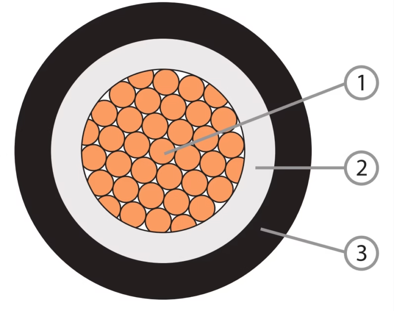
The following diagram represents the typical layer structure of a heavy-duty mining cable compliant with SRPS N.C5.374:2005:
Layer 1: Conductor
Class 5 or Class 6 stranded copper conductor per IEC 60228. Nominal cross-sections typically range from 25 mm² to 240 mm² for medium-voltage mining applications. Tinned copper optional for enhanced corrosion resistance.
Layer 2: Conductor Screen
Semiconducting layer (0.5-1.0 mm thickness) for medium and high-voltage cables. Provides uniform electric field distribution and prevents partial discharge inception. Material: carbon-filled polymeric compound.
Layer 3: Primary Insulation
EPR or XLPE insulation with thickness calculated per SRPS standards based on voltage rating. For 3.6/6 kV: minimum 2.5 mm. For 18/20 kV: minimum 5.5 mm. Provides electrical insulation and mechanical support.
Layer 4: Insulation Screen
Semiconducting layer applied over insulation for voltage stress control. Strippable design facilitates field termination. Essential for medium and high-voltage applications to ensure cable longevity.
Layer 5: Separator/Bedding
Non-hygroscopic tape or extruded polymer layer. Protects insulation during armoring process and provides cushioning. Typical thickness: 0.3-0.8 mm depending on cable size.
Layer 6: Metallic Shield/Armor
Copper wire screen or galvanized steel wire armor. Provides mechanical protection, grounding path, and electromagnetic shielding. Wire diameter: 0.6-2.5 mm based on cable rating and application.
Layer 7: Outer Sheath
Chloroprene rubber (CPE) or EPR compound. Thickness per SRPS N.C0.025:1991 calculation method. Minimum 2.0 mm for mining cables. Provides abrasion, oil, flame, and moisture resistance.
Optional: Identification Marking
Permanent marking per SRPS N.C0.006:1984 including manufacturer, standard designation, voltage rating, and year of manufacture. Marking interval: every 1000 mm ±50 mm along cable length.
4.5 Cable Assembly for Multi-Core Configurations
Multi-core cables for mining applications typically utilize one of three assembly configurations:
Circular Lay Configuration: Individual insulated cores are laid together in a circular formation around a central filler. This configuration provides balanced mechanical properties and facilitates even current distribution across phases. Commonly used in three-core and four-core power cables.
Flat Configuration: Cores are arranged in a single plane, facilitating easier installation in confined spaces. This design is specified in SRPS N.C3.235:1974 for flat installation conductors. The configuration reduces overall cable diameter while maintaining electrical clearances.
Sector-Shaped Core Configuration: Cores have sector-shaped cross-sections instead of circular, allowing closer packing and reduced overall cable diameter. This design is particularly effective for three-phase cables, reducing material usage while maintaining electrical performance specifications.
5. Standards Compliance and Certification Framework
5.1 Primary SRPS Standards for Mining Cables
| Standard Number | Year | Title | Scope |
|---|---|---|---|
| SRPS N.C0.505 | 1982 | Transport reels for electric cables, conductors and metallic ropes | Specifies basic dimensions for cable reels used in mining and industrial applications |
| SRPS N.C0.010 | 1984 | Colors for marking and identification system of cable cores | Establishes color coding for conductors in cables rated up to 1 kV |
| SRPS N.C0.190 | 1991 | Heat-resistant elastomeric insulations and protective layers | Material specifications for high-temperature applications |
| SRPS N.C5.353 | 1994 | Mining cables with rubber insulation, types GN 53, EPN 53, GN 55, EPN 55 | Specifications for 0.6/1 kV mining cables with rubber insulation and sheath |
| SRPS N.C5.360 | 1994 | Mining cables for electrical devices and lighting | Rated voltage 0.6/1 kV for underground mining lighting and equipment |
| SRPS N.C5.364 | 1994 | Mining cables for portable transformers, types EPN 64 and EPN 65 | Specifications for cables rated up to 3.6/6 kV for transformer connections |
| SRPS N.C5.374 | 2005 | Heavy duty flexible mining cables for surface mining | Rated voltages 3.6/6 kV up to 20/35 kV for surface mining and similar purposes |
5.2 Harmonized European Standards
Serbia has adopted numerous European standards through the harmonization process managed by the Institute for Standardization of Serbia. These harmonized standards carry both SRPS and EN designations, ensuring compatibility with European Union directives while maintaining Serbian regulatory requirements.
| SRPS EN Standard | Harmonized Directive | Application |
|---|---|---|
| SRPS EN IEC 60228:2024 | Low Voltage Directive 2014/35/EU | Conductor specifications for all cable types |
| SRPS EN 50525-2-21:2011 | Low Voltage Directive 2014/35/EU | Flexible cables with crosslinked elastomeric insulation, 450/750 V |
| SRPS EN IEC 60332-3-22:2019 | Construction Products Regulation | Flame propagation testing for bunched cables |
| SRPS HD 361 S4:2020 | Multiple Directives | Designation system for harmonized power cables and cords |
The harmonization with European standards ensures that SRPS-compliant cables meet essential safety requirements prescribed in EU directives, particularly the Low Voltage Directive (LVD) 2014/35/EU.[6] This alignment facilitates trade within European markets and provides manufacturers with clear pathways for demonstrating compliance through harmonized standards.
5.3 Related International Standards
SRPS cables must often meet additional international standards depending on export markets and application requirements:
- IEC 60502: Power cables with extruded insulation and their accessories for rated voltages from 1 kV to 30 kV
- IEC 60811: Electric and optical fiber cables – Test methods for non-metallic materials
- ISO 9001: Quality management system requirements for cable manufacturing facilities
- MSHA Standards (30 CFR Parts 18, 75, 77): Mine Safety and Health Administration standards for cables used in US mining operations[7]
- AS/NZS Standards: Australian and New Zealand standards for mining cables, ensuring compatibility with mining operations in these regions
5.4 Certification and Testing Requirements
Manufacturers of SRPS-compliant cables must conduct comprehensive testing to verify compliance. The Institute for Standardization of Serbia operates certification programs that assess both product conformity and manufacturing quality systems.
Mandatory Type Testing Requirements
According to SRPS testing protocols, manufacturers must perform type tests on representative cable samples before market introduction. These tests include electrical resistance measurement per SRPS EN IEC 60228, insulation resistance testing at specified voltages, dielectric strength verification, flame propagation assessment per SRPS EN IEC 60332-3-22, mechanical property evaluation including tensile strength and elongation, and environmental resistance testing for oil, abrasion, and thermal cycling.
Routine testing conducted on production runs ensures ongoing quality control. These tests typically include conductor resistance verification, insulation resistance measurement, high-voltage testing to detect insulation defects, and dimensional checks to confirm compliance with specified tolerances.
6. Safety Thresholds and Critical Parameters
6.1 Electrical Safety Limits
SRPS standards establish strict safety thresholds to protect personnel and equipment. These limits are based on comprehensive risk analysis and align with international best practices for electrical safety in hazardous environments.
| Parameter | Safety Threshold | Test Method | Consequence of Exceeding |
|---|---|---|---|
| Insulation Resistance (1 kV cables) | Minimum 1 MΩ/km at 20°C | SRPS N.C0.037 | Risk of ground fault, shock hazard, equipment damage |
| Dielectric Strength (0.6/1 kV) | Withstand 3.5 kV AC for 5 minutes | SRPS N.C0.040 | Insulation breakdown, catastrophic failure |
| Leakage Current | Maximum 5 mA per circuit at rated voltage | IEC 60364 | Personnel shock risk, fire initiation |
| Conductor Temperature (PVC) | Maximum 70°C continuous operation | Thermal monitoring | Insulation degradation, accelerated aging |
| Conductor Temperature (XLPE/EPR) | Maximum 90°C continuous operation | Thermal monitoring | Premature failure, reduced service life |
| Short Circuit Temperature | Maximum 160°C (PVC), 250°C (XLPE/EPR) | Calculated per IEC 60364-5-52 | Permanent insulation damage, fire risk |
6.2 Mechanical Safety Limits
Mining and industrial cables must withstand mechanical stresses without compromising safety. SRPS standards specify minimum mechanical performance criteria:
Tensile Load During Installation
Maximum Pulling Force: 5.0 kg/mm² of conductor cross-section
Example: 50 mm² cable maximum 250 kg tension
Exceeding this limit may cause conductor stretching, insulation damage, or connection failure.
Impact Resistance
Mining Cables: Must withstand 5 J impact without sheath penetration
Test Method: Drop hammer test per SRPS N.C0.050
Ensures cables survive typical mining environment impacts.
Crush Resistance
Minimum Load: 500 N/cm cable width
Duration: 5 minutes application
Prevents damage from equipment passage or material storage on cables.
Abrasion Cycles
Minimum Performance: 1,000 cycles per SRPS N.C0.050
Failure Criterion: Sheath penetration or 50% thickness reduction
Critical for trailing cables in continuous motion.
6.3 Environmental Operating Limits
| Environmental Factor | Acceptable Range | Critical Threshold | Required Protection |
|---|---|---|---|
| Ambient Temperature (Operation) | -25°C to +50°C | Below -40°C or above +60°C | Temperature-rated insulation selection |
| Ambient Temperature (Installation) | -5°C to +40°C | Below -15°C or above +50°C | Pre-warming or installation delay required |
| Humidity | 0-95% RH non-condensing | Continuous water immersion | Waterproof sheath and sealed terminations |
| Altitude | Up to 1,000 m above sea level | Above 2,000 m | Voltage de-rating or enhanced insulation |
| Chemical Exposure | Minimal industrial atmosphere | Direct acid/alkali contact | Chemical-resistant sheath material required |
6.4 Mining-Specific Safety Requirements
Underground mining operations present unique hazards requiring additional safety measures. SRPS N.C5.374:2005 and related mining cable standards incorporate requirements derived from international mining safety practices.
Critical Mining Safety Thresholds
Ground Fault Protection: Maximum 30 mA leakage current before automatic disconnection. Mining cables must incorporate integrated ground check monitors or be used with ground fault detection systems compliant with MSHA 30 CFR 75.1002 requirements.[8]
Flame Resistance: Self-extinguishing within 60 seconds of ignition source removal per SRPS EN IEC 60332-3-22. Cables used underground must not propagate flame along bundled installations exceeding 2.5 meters vertical spread.
Maximum Splice Count: Not more than five temporary splices permitted in any single length of portable mining cable per MSHA 30 CFR 18.35. Each splice must maintain full electrical and mechanical integrity equivalent to unspliced cable.
Trailing Cable Inspection Frequency: Visual inspection required at beginning of each shift for mining equipment rated above 440V. Complete inspection including jacket condition, splice integrity, and grounding continuity must occur weekly during active use.
6.5 Overcurrent Protection Coordination
Proper selection of overcurrent protective devices is essential for cable safety. SRPS standards require that protective devices operate before cables reach damage thresholds:
| Conductor Size (mm²) | Maximum Fuse Rating (A) | Maximum Circuit Breaker (A) | Cable Damage Threshold (A) |
|---|---|---|---|
| 1.5 | 16 | 16 | 24 |
| 2.5 | 20 | 25 | 33 |
| 4 | 25 | 32 | 43 |
| 6 | 32 | 40 | 55 |
| 10 | 40 | 50 | 76 |
| 16 | 63 | 63 | 101 |
| 25 | 80 | 100 | 135 |
| 35 | 100 | 125 | 167 |
| 50 | 125 | 160 | 202 |
Protection devices must be sized to prevent conductor temperature from exceeding safe limits during overload conditions while allowing normal starting currents for motors and other inductive loads.
7. Precautions for Use and Installation Best Practices
7.1 Pre-Installation Inspection
Before installing SRPS-compliant cables, thorough inspection is mandatory to ensure product integrity and suitability for the intended application. The following inspection procedures should be performed:
- Documentation Verification: Confirm that cable markings match specifications on delivery documentation including voltage rating, conductor size per SRPS EN IEC 60228, insulation type, and manufacturing date. Verify that test certificates are present and valid.
- Visual Examination: Inspect sheath for cuts, abrasions, or mechanical damage that could compromise cable integrity. Check reel condition and verify proper cable wrapping without excessive tension or compression. Examine cable ends for moisture ingress or contamination.
- Storage Conditions: Verify that cables have been stored within acceptable temperature ranges specified by manufacturer, typically -5°C to +40°C. Ensure storage area is free from direct sunlight, chemical exposure, or physical hazards. Confirm that cable reels are elevated off ground to prevent moisture absorption.
- Electrical Testing (For Critical Applications): Perform insulation resistance testing using appropriate megohmmeter rated for cable voltage. Minimum acceptable values: 1 MΩ/km for cables up to 1 kV; 20 MΩ/km for cables 1-10 kV; 50 MΩ/km for cables above 10 kV.
7.2 Installation Guidelines
Temperature Considerations
Install cables only when ambient temperature is within specified range per SRPS standards. For PVC-sheathed cables, minimum installation temperature is 0°C. For rubber-sheathed mining cables, minimum is -15°C. Pre-warm cables stored in cold conditions before installation to prevent insulation cracking.
Bending Radius Compliance
Never exceed minimum bending radius during installation. Fixed installation cables: 6× overall diameter. Flexible mining cables: 10× overall diameter during installation, 15× diameter for frequent flexing service. Use appropriate pulling equipment and guides to prevent radius violations.
Pulling Tension Control
Monitor pulling force continuously during installation. Maximum sidewall pressure: 300 N/m for cables without armor; 500 N/m for armored cables. Use pulling eyes or grips that distribute force across conductor cross-section. Never pull on metallic shield or armor.
Support and Securing
Provide adequate support per SRPS N.C5.020 requirements. Vertical runs: support intervals ≤2 meters for cables above 25 mm diameter. Horizontal runs: support intervals ≤1.5 meters. Use appropriate cleats, cable trays per SRPS EN 61537:2009, or conduit systems per SRPS EN 50085.
7.3 Termination and Connection Procedures
Proper termination is critical for ensuring electrical safety and long-term reliability. SRPS-compliant installations must follow these practices:
Preparation: Remove cable sheath using appropriate stripping tools, maintaining minimum clearances specified in cable datasheet. Avoid nicking conductor insulation during sheath removal. Clean exposed conductors and remove oxidation using appropriate wire brushes or cleaning solutions approved for cable material.
Stress Control (Medium Voltage Cables): For cables rated above 3 kV, install stress control cones or heat-shrink terminations that provide smooth transition of electric field. Follow manufacturer instructions precisely regarding dimension and installation technique. Failure to properly control electrical stress at terminations can lead to premature failure and safety hazards.
Connection Integrity: Use crimp terminals or compression connectors rated for conductor size and application environment. Ensure proper crimp tool calibration and verify die size matches connector specification. Apply appropriate torque to bolted connections per manufacturer specifications, typically 10-15 N·m for M8 connections, 20-30 N·m for M10 connections in power applications.
Grounding Requirements: Connect metallic shields and armor to protective earth per SRPS N.C0.006:1984 color coding standards. Ensure ground connection resistance is less than 0.1 Ω. For mining cables, verify ground continuity testing per MSHA requirements shows less than 0.5 Ω total circuit resistance including equipment grounding.
7.4 Operational Precautions
Critical Operational Warnings
Do Not Exceed Voltage Ratings: Never operate cables above their rated voltage classification. Temporary overvoltage during switching or fault conditions can cause insulation breakdown. Ensure proper surge protection is installed per SRPS power distribution standards.
Current Derating Required: Apply appropriate derating factors when cables are bundled, installed in conduits, or operate at elevated ambient temperatures. Example: PVC cable rated 50A at 30°C ambient must be derated to 35A when operating at 40°C ambient (0.71 derating factor).
Mining Equipment Mobility: For trailing cables on mobile mining equipment, implement cable management systems that prevent excessive bending, dragging, or crushing. Establish minimum approach distances to prevent cable contact with moving machinery. Monitor cable condition continuously during operation and remove from service immediately upon detecting damage.
Chemical Exposure Avoidance: Protect cables from direct contact with chemicals not specified in material compatibility documentation. Common mining chemicals like diesel fuel, hydraulic oils, and cleaning solvents can degrade certain sheath materials. Consult SRPS N.C0.190 specifications for material resistance data.
7.5 Inspection and Maintenance Schedule
| Inspection Type | Frequency | Key Checkpoints | Documentation Required |
|---|---|---|---|
| Visual Inspection (Fixed Cables) | Quarterly | Sheath condition, support integrity, termination security, identification marking visibility | Inspection log with findings and corrective actions |
| Visual Inspection (Mining Cables) | Daily before shift | Outer jacket damage, splice condition, connector integrity, ground wire continuity | Pre-shift checklist signed by operator |
| Detailed Physical Inspection | Monthly (mining), Semi-annually (fixed) | Abrasion severity, splice integrity, armor condition, bend radius compliance | Detailed report with measurements and photos |
| Electrical Testing | Annually (routine), After damage (emergency) | Insulation resistance, conductor continuity, ground resistance, dielectric integrity | Test certificate with measured values |
| Thermal Imaging | Annually for critical circuits | Hot spots at connections, overload indicators, thermal gradients along cable | Thermographic report with baseline comparison |
7.6 Replacement Criteria and Lifecycle Management
SRPS cables have finite service lives dependent on operating conditions. Establish replacement criteria based on the following factors:
Age-Based Replacement: Fixed installation cables in protected environments: 25-30 year typical service life. Mining trailing cables in continuous duty: 3-5 year typical service life. Portable cables in industrial applications: 5-10 year typical service life. These values assume normal operating conditions and proper maintenance.
Condition-Based Replacement: Replace cables immediately if insulation resistance falls below 0.5 MΩ/km, visible conductor through sheath damage, more than three repairs in single cable length, or evidence of overheating (discoloration, melted insulation). Replace cables proactively when jacket wear exceeds 50% thickness, flex life cycles approach manufacturer rating, or operating environment becomes more severe than cable rating.
8. Common Problems and Solutions
8.1 Installation-Related Issues
| Problem | Symptoms | Root Cause | Solution |
|---|---|---|---|
| Insulation Cracking | Visible cracks in outer sheath, reduced insulation resistance | Installation at temperature below minimum specification | Pre-warm cables before installation; replace damaged sections; verify temperature compliance |
| Conductor Stretching | Increased resistance readings, reduced flexibility, visible elongation | Excessive pulling tension during installation | Use pulling grips and tension monitoring; replace stretched sections; retrain installation crews |
| Insulation Damage at Bends | Ground faults, reduced dielectric strength at curves | Violation of minimum bending radius specifications | Install cable supports at proper spacing; use radius guides; replace damaged cable sections |
| Water Ingress at Terminations | Insulation resistance degradation, corrosion at connections | Inadequate sealing during termination procedure | Re-terminate using approved sealing methods; install drip loops; use heat-shrink moisture barriers |
8.2 Operational Failures
| Failure Mode | Indicators | Common Causes | Corrective Actions |
|---|---|---|---|
| Thermal Overload | Discolored insulation, melted conductor insulation, tripped overload protection | Current exceeding cable rating, inadequate derating for installation conditions, failed cooling systems | Verify actual load current; recalculate with derating factors; upgrade to higher capacity cable; improve ventilation |
| Ground Fault | Protective device trips, shock hazard detected, equipment malfunction | Insulation breakdown from moisture, mechanical damage to sheath, aging degradation | Locate fault using TDR or cable fault locator; replace damaged section; improve cable protection measures |
| Sheath Abrasion | Exposed insulation, eventual ground fault, visible wear pattern | Cable contact with moving machinery, inadequate support, sharp edges on cable route | Install protective conduit or abrasion guards; relocate cable away from hazard; use abrasion-resistant sheath material |
| Splice Failure | Intermittent power loss, heating at splice, resistance increase | Improper splice technique, moisture ingress, mechanical stress at splice | Re-splice using correct materials and procedure; provide mechanical support; consider replacing with unspliced cable |
8.3 Mining-Specific Problems
Underground and surface mining operations present unique challenges that require specialized troubleshooting approaches:
Trailing Cable Fatigue
Problem: Conductor breakage from repeated flexing
Detection: Intermittent power, increased resistance
Solution: Implement cable rotation schedule; verify proper cable management systems; upgrade to higher flex-rated cable class; reduce operating speed if possible
Chemical Attack on Sheath
Problem: Softening, swelling, or cracking of rubber sheath
Detection: Visual deterioration, sticky surface texture
Solution: Identify incompatible chemical; substitute compatible sheath material per SRPS N.C0.190; implement chemical containment procedures
Coupling Damage
Problem: Ground fault at cable coupler connections
Detection: Ground check circuit activation, visible damage
Solution: Replace damaged couplers immediately; train operators on proper coupling procedure; implement coupler inspection program; use protective covers
Excessive Cable Dragging
Problem: Rapid wear from cable contact with ground
Detection: Sheath wear on bottom surface, debris accumulation
Solution: Adjust cable handling equipment; implement cable festoon systems; reduce cable length; install rollers or guides on cable route
8.4 Diagnostic Procedures
Systematic troubleshooting of SRPS cable problems requires appropriate test equipment and procedures:
Insulation Resistance Testing: Use megohmmeter rated for cable voltage plus 1 kV minimum. Test each conductor to ground and conductor-to-conductor. Compare results to baseline measurements and minimum acceptable values per SRPS standards. Temperature-correct readings using correction factors from IEC 60228 Annex B.
Time Domain Reflectometry (TDR): Effective for locating faults, splice locations, and impedance discontinuities in long cable runs. TDR instruments send pulse signal and analyze reflections to determine distance to fault. Accuracy typically ±1% of distance for quality instruments. Essential tool for underground mining cable troubleshooting.
Thermal Imaging: Infrared cameras detect overheating at connections, overloaded conductors, and failing splices. Perform thermal surveys under normal load conditions. Temperature differentials exceeding 15°C between similar connections indicate problems requiring investigation. Document baseline thermal signatures during commissioning for comparison.
Visual Inspection with Proper Lighting: Many cable problems are detectable through thorough visual examination. Use high-intensity portable lighting for underground inspections. Check entire cable length systematically, documenting any damage, wear, or anomalies. Pay particular attention to stress points at supports, bends, and terminations.
8.5 Emergency Response Procedures
Emergency Actions for Cable Failures
Immediate Power Isolation: If ground fault or short circuit is detected, de-energize circuit immediately using appropriate disconnection procedures. Lock out and tag circuit to prevent re-energization. Verify de-energization using appropriate voltage detection equipment rated for system voltage.
Personnel Safety: Evacuate personnel from area if electrical hazard present. Establish safety perimeter around damaged cable. For underground mining, implement emergency ventilation procedures if smoke or fumes detected. Contact emergency response personnel per site emergency action plan.
Damage Assessment: Once power confirmed isolated, inspect cable extent of damage. Document with photographs for incident investigation. Determine if emergency repair possible or if complete cable replacement required. For mining operations, notify MSHA or equivalent regulatory authority of significant electrical incidents per reporting requirements.
Temporary Repair Limitations: Emergency splices on mining cables must not exceed maximum count per MSHA 30 CFR 18.35 (five splices maximum). Temporary repairs are for emergency use only and must be replaced with permanent solutions during planned maintenance. All emergency repairs require documentation and inclusion in cable maintenance records.
9. Industry Applications and Case Studies
9.1 Underground Coal Mining Applications
Underground coal mining represents one of the most demanding environments for electrical cables. SRPS N.C5.353 and related standards address the unique requirements of this sector. Continuous mining machines operating at 3.6/6 kV require cables capable of withstanding constant flexing, exposure to coal dust and moisture, resistance to impact from roof falls or equipment contact, and reliable operation in methane-present atmospheres.
A typical underground coal mine deployment might utilize SRPS N.C5.364:1994 compliant cables for portable transformer connections supplying power at 3.6/6 kV. These cables feature EPR insulation providing 90°C continuous operation, chloroprene rubber sheath for oil and abrasion resistance, copper wire screen for ground fault protection, and Class 6 flexible conductors enabling 15,000+ flex cycles. The stringent flame resistance requirements of SRPS EN IEC 60332-3-22 ensure cables do not contribute to mine fire propagation.
9.2 Surface Mining and Quarry Operations
Surface mining operations utilizing draglines, electric shovels, and large-capacity drilling equipment require heavy-duty cables specified in SRPS N.C5.374:2005. These applications demand cables rated for voltages up to 20/35 kV, conductor sizes from 50 mm² to 240 mm² for high current capacity, and robust mechanical construction to withstand continuous reeling operations. The cables must maintain performance across temperature extremes from -25°C winter conditions to +50°C summer operation.
Integration with reeling cable systems for mobile machinery requires careful attention to cable construction details. The combination of heavy copper conductors, thick EPR insulation, and reinforced sheath results in cables weighing 10-20 kg per meter, necessitating substantial mechanical support systems and properly sized cable reels compliant with SRPS N.C0.505:1982 dimensional standards.
9.3 Industrial Manufacturing Facilities
Manufacturing plants rely on SRPS-compliant cables for power distribution, machine connections, and control systems. SRPS EN 50525-2-21:2011 specifies flexible cables suitable for connecting industrial machinery, robotic systems, and conveyor drives. These cables typically feature PVC or rubber insulation rated for 450/750 V operation, Class 5 flexible conductors for moderate flexing service, and oil-resistant sheaths suitable for machining and processing environments.
Fixed power distribution within manufacturing facilities utilizes SRPS N.C5.220:1983 cables with thermoplastic PVC insulation for voltages up to 10 kV. These cables provide reliable, economical power distribution for transformers, switchgear, and large motor loads. The cables’ resistance to industrial atmospheres containing metal dust, coolants, and process chemicals ensures long service life in harsh manufacturing environments.
9.4 Port Terminal and Maritime Applications
Port terminal operations require cables capable of withstanding marine environmental conditions. Container handling cranes, ship-to-shore gantries, and mobile cargo handling equipment utilize SRPS-compliant cables with specialized construction features including UV-resistant sheath compounds, enhanced corrosion protection for conductors and shields, and waterproof designs preventing saltwater ingress.
The demanding operational profile of port terminal reeling cables necessitates cables designed for millions of flex cycles. These applications typically employ Class 6 conductors with individual wire diameters of 0.2 mm or smaller, cross-linked polyethylene insulation for moisture resistance, and chlorosulfonated polyethylene (CSM) sheaths providing superior resistance to ozone, UV radiation, and seawater. Service life expectations of 10-15 years require careful material selection and robust quality control during manufacturing.
9.5 Comparison with International Mining Standards
SRPS mining cable standards share common objectives with international specifications but include region-specific requirements. Australian mining operations following AS/NZS 1802 and AS/NZS 2802 standards encounter similar technical challenges, with specifications addressing voltage ratings from 0.6/1 kV to 19/33 kV, flame resistance per AS/NZS 1660.5.3, and mechanical durability under Australian mining conditions.
| Specification Aspect | SRPS Standards | AS/NZS Standards | MSHA Standards (USA) |
|---|---|---|---|
| Voltage Rating (MV Mining) | 3.6/6 kV to 20/35 kV | 1.9/3.3 kV to 19/33 kV | 2.4/4.16 kV to 7.2/12.47 kV |
| Conductor Material | Copper (Class 5/6) | Copper (Class 5/6) | Copper (AWG sizing) |
| Insulation Options | EPR, XLPE, Rubber | EPR, XLPE | EPR (primarily) |
| Flame Testing | IEC 60332-3-22 Category A | AS/NZS 1660.5.3 | MSHA flame test (30 CFR 18.64) |
| Maximum Splices | Specified per application | Varies by mine site rules | 5 temporary splices maximum |
| Ground Monitoring | Per SRPS electrical safety | Mandatory per AS/NZS 3000 | Mandatory per 30 CFR 75.1002 |
Despite variations in specific test methods and voltage nomenclature, all three regulatory frameworks prioritize electrical safety, mechanical durability, and fire resistance. This convergence reflects global consensus on mining cable safety requirements and facilitates international trade in mining equipment and components.
9.6 Future Trends and Technology Development
Evolution of SRPS cable standards continues to address emerging industry needs. Current development areas include enhanced flame retardance meeting stricter environmental regulations, low smoke and fume emission cables for enclosed mining operations, integration of fiber optic elements for communications and monitoring, and adoption of halogen-free compounds reducing toxic gas emission during fire events.
Smart cable technologies incorporating embedded sensors for temperature, strain, and electrical parameters monitoring represent significant advancement opportunities. These systems enable predictive maintenance programs, reducing unexpected failures and extending cable service life. Implementation requires updates to SRPS standards addressing sensor integration, data communication protocols, and reliability requirements for monitoring systems.
References and Further Information
- [1] Technical Regulations and Standards in Serbia. Tehnis Portal. Available at: https://tehnis.privreda.gov.rs
- [2] Institute for Standardization of Serbia (ISS). SRPS EN IEC 60228:2024 – Conductors of Insulated Cables. Available at: https://iss.rs
- [3] International Electrotechnical Commission. IEC 60228:2023 – Conductors of Insulated Cables. Available at: https://webstore.iec.ch
- [4] SRPS EN IEC 60332-3-22:2019 – Tests on Electric and Optical Fibre Cables Under Fire Conditions – Vertical Flame Spread. Institute for Standardization of Serbia. Available at: https://iss.rs
- [5] IEC 60228 Standard Cable – Conductor Classifications and Requirements. Eland Cables Technical Library. Available at: https://www.elandcables.com
- [6] Harmonized Standards and EU Directives. Institute for Standardization of Serbia. Available at: https://iss.rs
- [7] Mine Safety and Health Administration (MSHA). High-Voltage Continuous Mining Machine Standards for Underground Coal Mines. Code of Federal Regulations 30 CFR Parts 18 and 75. Available at: https://www.federalregister.gov
- [8] MSHA Electrical Safety Standards. eCFR Title 30 Part 18 – Electric Motor-Driven Mine Equipment and Accessories. Available at: https://www.ecfr.gov
- [9] Mining Cable: The Complete Guide to Underground Mining Electrical Cables. TOT Cables Technical Resources. Available at: https://totcables.com
- [10] SRPS EN 50525-2-21:2011 – Electric Cables – Low Voltage Energy Cables. Institute for Standardization of Serbia. Available at: https://iss.rs


