
Type (N)TSCGECEWÖU Mining Reeling Cable MT MIN F-E PLUS Medium Voltage Flexible Power Cable: 3.6/6 – 12/20 kV | DIN VDE 0250 Part 813
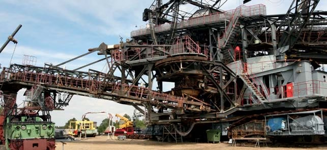
Type (N)TSCGECEWÖU Mining Reeling Cable MT MIN F-E PLUS
Medium Voltage Flexible Power Cable: 3.6/6 – 12/20 kV | DIN VDE 0250 Part 813
Cable Specifications at a Glance
Type: (N)TSCGECEWÖU Mining Reeling Cable
Standard: DIN VDE 0250 Part 813 | VDE 0207
Voltage Ratings:
3.6/6 kV
6/10 kV
8.7/15 kV
12/20 kV
Conductor Material: Tinned Copper, Class 5 (IEC 60228)
Primary Application: Mining Operations & Material Handling Equipment
What is a Type (N)TSCGECEWÖU Mining Reeling Cable?
The Type (N)TSCGECEWÖU Mining Reeling Cable represents a specialized category of medium voltage flexible power cables engineered specifically for the demanding conditions found in underground mining operations and material handling equipment. This cable designation, while complex in nomenclature, follows the systematic German cable naming convention established by DIN VDE standards.
The abbreviation breaks down as follows: N indicates a rubber compound construction, TSC refers to the tinned copper stranded conductor with semiconductive layers, G represents the rubber sheath, E denotes earth conductor protection, C signifies the concentric copper wire screen, and E emphasizes enhanced earth fault protection. The suffix WÖU indicates weather-resistant, oil-resistant, and suitable for UV exposure properties.
According to the VDE Institute, cables manufactured to DIN VDE 0250 Part 813 must meet stringent requirements for electrical, mechanical, and environmental performance in mining applications where safety is paramount.
Purpose and Primary Applications
Designed for Extreme Industrial Environments
The MT MIN F-E PLUS series cable is specifically engineered for flexible energy distribution lines in underground mines and alongside material handling equipment. Unlike standard industrial cables, this mining reeling cable must withstand continuous mechanical stress from reeling and unreeling operations while maintaining electrical integrity.
Key Application Areas:
- Underground Mining Machinery: Continuous miners, longwall shearers, shuttle cars, and roof bolters requiring mobile power distribution
- Surface Mining Equipment: Draglines, electric rope shovels, and bucket-wheel excavators operating in open-pit mines
- Port Material Handling: Ship loaders, stackers, reclaimers, and mobile harbor cranes (see more at reelingcable.com)
- Heavy Industry: Steel mills, cement plants, and manufacturing facilities with mobile heavy equipment
- Power Distribution Systems: Temporary and permanent electrical installations in mining sites requiring medium voltage power transmission
Technical Characteristics and Features
Outstanding Performance Features:
- Enhanced Electrical Safety: Integrated semiconductive layers over conductors and insulation provide controlled electrical field distribution, preventing partial discharge and corona effects that can lead to premature cable failure
- Tinned Copper Conductors: Tin coating on copper strands prevents oxidation in humid mining environments, maintaining long-term conductivity and reducing connection resistance
- Multi-Layer Insulation System: 3GI3 quality rubber compound insulation combined with inner and outer semiconductive rubber layers ensures uniform voltage stress distribution across all voltage ratings
- Comprehensive Earth Protection: Triple earth conductor configuration (3×25/3E to 3×95/3E depending on phase conductor size) with individual copper wire screening provides redundant safety against earth faults
- Dual-Sheath Protection: Inner sheath (GM1b quality) provides mechanical separation, while outer sheath (5GM3 quality) delivers exceptional resistance to oils, chemicals, abrasion, and environmental exposure
- High Temperature Performance: Maximum continuous conductor temperature of 90°C with short-circuit capability up to 250°C, ensuring reliable operation in thermally demanding mining environments
- Cold Weather Operation: Rated for ambient temperatures from -40°C to +80°C, maintaining flexibility and electrical properties in extreme conditions
Electrical Performance Data:
| Voltage Rating (U₀/U) | Test Voltage | Max AC Operating Voltage | Current Rating Reference |
|---|---|---|---|
| 3.6/6 kV | 11 kV | 4.2/7.2 kV | VDE 0298 Part 4 |
| 6/10 kV | 17 kV | 6.9/12 kV | VDE 0298 Part 4 |
| 8.7/15 kV | 24 kV | 10.4/18 kV | VDE 0298 Part 4 |
| 12/20 kV | 29 kV | 13.9/24 kV | VDE 0298 Part 4 |
Detailed Material Structure and Construction
Layer-by-Layer Construction Analysis:
1. Phase Conductors (Core)
| Material | Tinned copper wire |
| Construction Class | Class 5 per VDE 0295 and IEC 60228 (flexible stranded) |
| Cross Sections Available | 25 mm², 35 mm², 50 mm², 70 mm², 95 mm², 120 mm², 150 mm², 185 mm² |
| Conductor Temperature | 90°C continuous, 250°C short-circuit |
2. Insulation System
- Semiconductive Tape: Applied directly over conductor to control electrical field at conductor surface
- Primary Insulation: 3GI3 quality rubber compound per VDE 0207 Part 20 – provides electrical insulation rated for medium voltage service
- Inner Semiconductive Layer: Extruded simultaneously with insulation to eliminate air gaps
- Outer Semiconductive Layer: Creates uniform electrical field distribution to outer screen
3. Protective Earth Conductors
| Material | Bare copper wire |
| Construction | Individual copper wire screen over each conductor |
| Configuration | 3 separate earth conductors (matching or proportional to phase conductor size) |
| Function | Redundant earth fault protection and electromagnetic shielding |
4. Central Filler
Rubber compound applied over textile polyester support positioned at the center of the three-phase assembly. This filler maintains circular cable geometry, reduces void spaces, and provides additional mechanical support during bending operations.
5. Core Assembly
Three insulated conductors with individual earth screens are twisted together with appropriate lay length to minimize electromagnetic interference and ensure balanced electrical characteristics. A semiconductive tape is wound over the twisted core assembly to maintain electrical uniformity.
6. Inner Sheath (First Protective Layer)
| Material | GM1b quality rubber compound per VDE 0207 Part 21 |
| Thickness | Per VDE 0250 Part 813 Table 2 (varies with cable diameter) |
| Function | Mechanical separation between core assembly and outer sheath, provides cushioning effect |
7. Outer Sheath (Final Protection)
| Material | 5GM3 quality rubber compound per VDE 0207 Part 21 |
| Thickness | Per VDE 0250 Part 813 Table 2 (heavy-duty mining specification) |
| Properties | Oil-resistant, weather-resistant, abrasion-resistant, flame-retardant |
| Color | Typically black with identifying markings |
The 5GM3 rubber compound represents a specialized formulation that provides exceptional mechanical protection while maintaining flexibility. This material meets stringent requirements for oil resistance (per IEC 60811-2-1), ozone resistance, and flame retardancy (IEC 60332-1-2).
Compliance with International Standards
Primary Certification Standards:
Standard Requirements and Verification:
| Standard | Requirement | Cable Compliance |
|---|---|---|
| DIN VDE 0250-813 | Mining cable construction, dimensions, test methods | Full compliance – design basis standard |
| IEC 60228 | Conductor class and construction | Class 5 flexible conductor |
| IEC 60332-1-2 | Flame retardant properties | Passes vertical flame test |
| IEC 60811-2-1 | Oil resistance and ozone aging | Type 2 oil resistance, ozone resistant |
| HD 22.16 | Water immersion behavior | Suitable for wet conditions |
| VDE 0298-3 | Installation bending radius | 15x outer diameter minimum |
| VDE 0298-4 | Current carrying capacity | Rated per conductor size and installation method |
Mining Safety Regulations:
Beyond electrical standards, mining reeling cables must comply with mining-specific safety regulations that vary by jurisdiction:
- European Union: Machinery Directive 2006/42/EC and ATEX Directive for potentially explosive atmospheres
- United States: MSHA (Mine Safety and Health Administration) requirements for underground and surface mining
- Australia: AS/NZS standards for mining electrical installations (reference amplexmining.com.au for Australian specifications)
- International: IEC 60079 series for equipment in explosive gas atmospheres
Safety Thresholds and Operating Limits
Critical Safety Parameters:
| Parameter | Specification | Safety Margin |
|---|---|---|
| Maximum Conductor Temperature | 90°C continuous operation | Do not exceed – insulation degradation beyond this point |
| Short Circuit Temperature | 250°C maximum (5 seconds duration) | Emergency rating only – requires cable inspection after event |
| Minimum Ambient Temperature | -40°C static installation | Flexibility reduced at low temperatures – handle with care |
| Maximum Ambient Temperature | +80°C | Derate current capacity above +40°C per VDE 0298-4 |
| Minimum Bending Radius (Installation) | 15x overall cable diameter | Tighter bending causes permanent conductor damage |
| Minimum Bending Radius (Operation) | 20x overall cable diameter | For reeling drums and continuous flexing applications |
| Maximum Tensile Load During Installation | 15 N/mm² of conductor area | Applies pulling force to conductors only – never pull on sheath |
| Voltage Test (Routine) | 2.5 x U₀ for 5 minutes | Factory test – do not exceed in field without proper equipment |
Current Carrying Capacity (Ampacity):
Current ratings must be calculated according to VDE 0298 Part 4, considering multiple factors:
- Conductor cross-sectional area
- Installation method (buried, in air, on cable tray, on reel)
- Ambient temperature (standard rating at 30°C for buried, 40°C for in-air installations)
- Grouping factor (multiple cables installed together)
- Duty cycle (continuous vs. intermittent operation)
- Altitude (derating required above 1000m elevation)
Electrical Safety Thresholds:
Mechanical Stress Limits:
Mining reeling cables experience unique mechanical stresses that must remain within design limits:
- Reeling Cycles: Designed for minimum 50,000 reeling cycles under normal conditions (varies with bending radius and tension)
- Crushing Resistance: Withstands 1000 N/cm width for cables up to 30mm diameter
- Impact Resistance: Designed to absorb impact energy from falling rocks and equipment without penetration
- Abrasion Resistance: Outer sheath maintains integrity after 40,000 abrasion cycles per IEC 60811-1-3
Precautions for Use and Best Practices
Installation Guidelines:
Critical Installation Precautions:
- Temperature Considerations: Do not install cables when ambient temperature is below -25°C unless special cold-weather handling procedures are implemented. Cold rubber becomes stiff and prone to cracking during bending.
- Pulling Stress: Use proper pulling equipment with swivel connections to prevent cable twisting. Install pulling grips on conductors, never on the outer sheath. Monitor pulling tension continuously and stop if resistance suddenly increases.
- Bending Radius: Use properly sized cable guides, rollers, and reel drums. The drum diameter should be at least 30x the cable outer diameter for reeling applications. Mark minimum bending radius clearly at installation sites.
- Termination Preparation: Use only trained personnel for cable termination. Follow manufacturer’s instructions precisely for stress cone installation, semiconductive layer removal, and earth screen termination. Improper termination is the leading cause of field failures.
- Testing After Installation: Perform insulation resistance testing at 1000V DC for at least 1 minute. Minimum acceptable resistance is 100 MΩ·km at 20°C. Higher readings are normal for new cables. Record baseline values for future comparison.
Operational Precautions:
During Mining Operations:
- Visual Monitoring: Implement daily cable inspection protocols. Look for cuts, abrasion marks, crushing damage, or abnormal heating patterns. Any visible damage requires immediate investigation.
- Reeling Tension Control: Maintain constant cable tension on reeling drums. Loose cable wraps can cause layer-to-layer damage and crushing. Install tension monitoring systems on critical reeling applications.
- Contamination Prevention: Keep cables clean from coal dust, oil spills, and chemical contamination. While the 5GM3 sheath is oil-resistant, prolonged exposure to aggressive chemicals may cause degradation. Establish regular cleaning procedures.
- Overload Prevention: Install properly rated overcurrent protection devices. Do not rely on upstream protection alone. Local protection reduces fault energy and limits damage during short circuits.
- Earth Continuity Verification: Test earth conductor continuity quarterly. Verify that all three earth conductors remain intact and properly connected at both ends. A single broken earth conductor reduces safety redundancy.
- Daily: Visual inspection of accessible cable sections
- Weekly: Inspection of terminations and connection points
- Monthly: Thermal imaging of critical sections under load
- Quarterly: Insulation resistance testing and earth continuity verification
- Annually: Partial discharge testing for medium voltage cables
Environmental Considerations:
- Water Exposure: While rated for wet conditions per HD 22.16, prolonged submersion can lead to water tree formation in insulation. Ensure proper drainage and avoid standing water around cables.
- UV Exposure: For outdoor installations, the WÖU designation indicates UV resistance, but covering cables with appropriate protection extends service life significantly.
- Chemical Exposure: Maintain compatibility charts for all chemicals present in the mining environment. Test new or unknown chemicals on cable samples before widespread exposure.
- Rodent Protection: In areas with rodent activity, install physical barriers or protective conduit. Rodent damage to mining cables can cause dangerous electrical faults.
Emergency Procedures:
- Immediately de-energize the affected circuit using proper lockout/tagout procedures
- Verify complete de-energization with appropriate voltage testing equipment
- Isolate and barricade the damaged cable section to prevent personnel access
- Contact qualified electrical personnel for damage assessment
- Do not attempt field repairs on damaged medium voltage cables – replacement is typically required
- Document the incident and investigate root cause to prevent recurrence
Common Problems and Troubleshooting
Frequently Encountered Issues:
1. Premature Cable Failure (Before Expected Service Life)
Symptoms: Insulation breakdown, earth faults, or conductor damage occurring before the typical 10-15 year service life expectancy.
Common Causes:
- Exceeding minimum bending radius during installation or operation
- Continuous operation above rated current capacity causing thermal aging
- Improper cable termination leading to electrical stress concentration
- Mechanical damage from sharp edges on equipment or support structures
- Chemical attack from incompatible substances
Solutions:
- Conduct thorough root cause analysis using thermal imaging and partial discharge testing
- Review installation records and verify compliance with bending radius requirements
- Implement ampacity calculations and install temperature monitoring systems
- Upgrade to larger conductor sizes if thermal issues persist
- Install cable protection systems (sheaves, guides, rollers) at wear points
2. Sheath Cracking and Deterioration
Symptoms: Visible cracks in outer sheath, loss of flexibility, or surface degradation exposing inner layers.
Common Causes:
- Ozone exposure in high-voltage environments or from electrical discharge
- UV degradation from prolonged outdoor exposure without protection
- Cold weather operation below rated temperature causing embrittlement
- Chemical incompatibility with specific oils or solvents
- Natural rubber aging accelerated by high temperatures
Solutions:
- Implement UV protection measures (cable covers, conduit) for outdoor installations
- Verify chemical compatibility before cable deployment
- Replace cables showing significant sheath deterioration before inner sheath compromise
- Consider alternative cable types with thermoplastic sheaths for extreme chemical environments
- Establish age-based replacement programs for cables in harsh conditions
3. Conductor Heating Beyond Normal Operating Temperature
Symptoms: Abnormal warmth detected during thermal inspection, temperature rise above 90°C, or heat-related trips of protection devices.
Common Causes:
- Undersized cable for actual load current
- High resistance connections at terminations
- Harmonic currents from variable frequency drives increasing effective current
- Damaged conductor strands reducing effective cross-section
- Inadequate ventilation in cable installation preventing heat dissipation
Solutions:
- Verify actual load current against cable ampacity calculations
- Inspect and re-torque all termination connections
- Perform harmonic analysis and install filters if necessary
- Consider parallel cable runs to reduce current per cable
- Improve cable routing to enhance natural convection cooling
4. Earth Fault Trips and Ground Leakage
Symptoms: Frequent earth fault protection activation, measurable leakage current, or reduced insulation resistance.
Common Causes:
- Water ingress through damaged sheath or poorly sealed terminations
- Insulation degradation from thermal, mechanical, or electrical stress
- Contamination of insulation surfaces with conductive materials
- Partial discharge activity eroding insulation over time
- Manufacturing defects (rare in quality cables but possible)
Solutions:
- Perform time-domain reflectometry (TDR) testing to locate fault positions
- Conduct partial discharge testing to assess insulation condition
- Verify proper sealing of all cable terminations and joints
- Implement predictive maintenance program with trending of insulation resistance
- Replace cables showing progressive insulation deterioration
5. Mechanical Damage from Reeling Operations
Symptoms: Flattened or deformed cable cross-section, visible conductor imprints on sheath, or internal conductor damage.
Common Causes:
- Incorrect drum diameter (too small for cable size)
- Layer-to-layer crushing from loose reeling
- Exceeding maximum reeling speed causing dynamic stress
- Foreign objects trapped between cable layers
- Improper tensioning during reeling and unreeling
Solutions:
- Verify drum diameter meets 30x cable diameter minimum
- Install automatic tension control systems on reeling equipment
- Implement regular inspection of cable condition on drum
- Train operators on proper reeling procedures and speed limits
- Consider level-wind mechanisms for consistent layer formation
6. Connection and Termination Failures
Symptoms: Local heating at termination points, corona discharge, or complete connection failure.
Common Causes:
- Improper stress cone installation leaving air gaps
- Incorrect torque on connection hardware
- Contamination during termination process
- Use of incompatible or inferior termination materials
- Failure to follow manufacturer’s termination procedures
Solutions:
- Require certification for personnel performing MV cable terminations
- Use only approved termination kits specified for the cable type
- Follow detailed termination procedures with quality checkpoints
- Perform partial discharge testing on critical terminations after installation
- Maintain clean working environment during termination activities
- On-site cable testing and failure analysis
- Custom cable design for unique mining applications
- Training programs for installation and maintenance personnel
- Ampacity calculations and thermal modeling
- Cable selection for new projects
Complete Technical Specifications Table
Available Cable Configurations (6/10 kV Example):
| Conductor Size | Min Diameter | Max Diameter | Approx. Weight | Max Tensile Load |
|---|---|---|---|---|
| 3×25 + 3×25/3E | 43.9 mm | 46.2 mm | 2910 kg/km | 1125 N |
| 3×35 + 3×25/3E | 45.4 mm | 47.7 mm | 3270 kg/km | 1575 N |
| 3×50 + 3×25/3E | 48.5 mm | 50.9 mm | 3900 kg/km | 2250 N |
| 3×70 + 3×35/3E | 54.1 mm | 56.5 mm | 5050 kg/km | 3150 N |
| 3×95 + 3×50/3E | 58.4 mm | 60.8 mm | 6190 kg/km | 4275 N |
| 3×120 + 3×70/3E | 62.5 mm | 65.5 mm | 7490 kg/km | 5400 N |
| 3×150 + 3×70/3E | 68.9 mm | 72.0 mm | 9020 kg/km | 6750 N |
| 3×185 + 3×95/3E | 71.9 mm | 75.0 mm | 10330 kg/km | 8325 N |
Note: Similar configurations available for 3.6/6 kV, 8.7/15 kV, and 12/20 kV voltage ratings with corresponding diameter and weight variations. Contact our sales team for complete specifications.
Get Expert Support for Your Mining Cable Project
Anhui Feichun Special Cable Co., Ltd. provides comprehensive technical support, custom cable solutions, and worldwide delivery for mining operations.
International Sales
+86 13855123218
WhatsApp, WeChat, and phone support
Related Resources and References
Technical Standards and Documentation:
- VDE Institute – German electrical engineering standards organization
- International Electrotechnical Commission (IEC) – Global electrical standards
- IEC 60228 – Conductors of insulated cables
- CENELEC – European Committee for Electrotechnical Standardization
Feichun Cable Product Lines:
- Reeling Cables – Complete range for port and mining machinery
- Australian Mining Cables – AS/NZS compliant mining cable solutions
- Crane and Festoon Cables – Specialized cables for overhead cranes
- Latin American Mining Cables – Cables mineros para operaciones en América Latina
- Feichun Cable (繁體中文) – 適用於華語地區的專業電纜解決方案
Industry Associations:
- International Copper Association – Copper conductor standards and applications
- IEEE Power & Energy Society – Electrical installation guidelines
- Society of Mining Engineers – Mining equipment electrical standards


