
High-Flexibility Salt-Fog Resistant Cables for Port & Underground Mining Applications
A comprehensive engineering analysis of Feichun’s proprietary EPR/CPE/PCP cable systems — from ship-to-shore crane reeling to underground drag applications under UNE 22511 — with comparative benchmarking against market incumbents.
📋 Technical Article Contents
- The Port Electrification Challenge: Why Standard Cables Fail at the Waterfront
- Salt-Fog Corrosion Mechanics & IEC 60068-2-11 Qualification
- Conductor Architecture: Class 5 vs. Class 6 for Dynamic Port Duty
- Insulation Selection: EPR vs. XLPE vs. PVC — A Port Environment Verdict
- Outer Sheath Systems: CPE, PCP, and Polyurethane — Performance Matrix
- Application Engineering: RTG Cranes, STS Cranes & Straddle Carriers
- Comparative Benchmarking: Feichun vs. Market Standards
- Port Cable SKU Portfolio & Selection Guide
- UNE 22511 Design Philosophy: Ultimate Flexibility for Underground Mobile Equipment
- Structural Deep-Dive: Conductor, Insulation, Earth Layout & Sheath
- UNE 22511 vs. UNE 22512: A Technical Differentiation Analysis
- Benchmarking Against Nexans Eproneo Minas: Drop-in Replacement Parameters
- Mechanical Endurance: Torsion, Tensile & Bending Cycle Analysis
- Mining Compliance: Flame Retardancy, Gas Generation & Regulatory Framework
Port & Harbor Salt-Fog Resistant Flexible Cable
1. The Port Electrification Challenge: Why Standard Cables Fail at the Waterfront
Modern container terminals represent one of the most electrically hostile environments encountered in industrial infrastructure. Rubber-tyred gantry (RTG) cranes, ship-to-shore (STS) cranes, straddle carriers, and automated guided vehicles (AGVs) demand cables that simultaneously satisfy contradictory engineering requirements: they must be supple enough to spool onto drums with sub-500 mm radii, yet robust enough to resist the relentless triple assault of marine salt aerosol, mechanical fatigue, and UV irradiation across operational lifespans exceeding 20 years.
The consequences of specifying a sub-standard cable in a port environment are not merely inconvenient — they are operationally catastrophic. A single cable failure on an STS crane serving a Panamax vessel can idle a berth for 6–12 hours, costing terminal operators USD 15,000–50,000 per incident in lost throughput and demurrage charges. Across a terminal fleet of 12 RTG cranes, cable-related downtime accounts for an estimated 8–14% of total unplanned outage hours according to aggregated maintenance data from major European and Asian container ports.
Standard cables — even those marketed as “flexible” or “marine-grade” — fail in port environments through three distinct pathways:
- Electrochemical sheath degradation: NaCl-laden aerosol penetrates micro-cracks in PVC sheaths and initiates pitting corrosion on copper conductors. Standard PVC compounds, containing plasticizers that migrate over time, accelerate this process by creating a progressively more porous barrier.
- Flexural fatigue fracture: Reeling cables on RTG cranes undergo 500–1,200 full coiling cycles per day. Class 2 or 4 stranded conductors — adequate for fixed or intermittently flexed installation — accumulate micro-fractures in individual wires after 50,000–100,000 cycles, leading to resistance increases and eventual open-circuit failure.
- UV-driven polymer chain scission: Quayside cables experience 2,000–3,500 hours of direct solar exposure annually. At ultraviolet wavelengths below 400 nm, PVC undergoes dehydrochlorination (loss of HCl), discoloring, embrittling, and ultimately cracking the outer sheath within 3–5 years — far short of the crane’s 25-year design life.
2. Salt-Fog Corrosion Mechanics & IEC 60068-2-11 Qualification
The behavior of cable materials under sustained salt-fog exposure is governed by a cascade of electrochemical and mechanical processes that the IEC 60068-2-11 test protocol is specifically designed to simulate. Understanding this mechanism is essential for engineers specifying cables in coastal, offshore, or port environments.
The Corrosion Cascade
Salt aerosol generated by wave action, spray, and wind at a container terminal creates a hygroscopic electrolyte film on exposed cable surfaces. The progression to failure follows a four-stage model:
- Surface wetting (Hours 0–100): NaCl solution forms a conductive film on the outer sheath. In CPE and PCP sheaths, the surface energy is low and the film is thin and discontinuous. In standard PVC, the plasticized surface attracts and retains a thicker, more persistent electrolyte layer.
- Micro-crack nucleation (Hours 100–300): Cyclic thermal expansion (day/night temperature differential of 15–35°C in tropical ports) and bending fatigue open hairline cracks in the sheath. Salt solution wicks into these cracks by capillary action, reaching the insulation layer.
- Insulation attack (Hours 300–600): At the copper-insulation interface, Cl⁻ ions initiate pitting corrosion (Cu → Cu⁺ + e⁻) and generate HCl, which accelerates polymer degradation. The insulation resistance (IR) drops — measured per IEC 60502-1 — as the electrolyte layer within the crack becomes conductive.
- Conductor embrittlement (Hours 600–1,000+): CuCl and Cu₂Cl₂ corrosion products form brittle deposits on individual copper wire strands. Under subsequent flexing, these embrittled wires fracture at a fraction of the force required to break un-corroded copper, dramatically reducing the cable’s mechanical life.
Feichun’s Salt-Fog Mitigation Architecture
The Feichun port cable addresses each stage of the corrosion cascade with a targeted material engineering response:
| Corrosion Stage | Standard PVC Cable Response | Feichun Port Cable Response | Technical Mechanism |
|---|---|---|---|
| Surface wetting | Plasticized PVC retains 0.3–0.8 mm electrolyte film | CPE / PCP sheath: <0.05 mm film due to low surface energy (30–34 mN/m) | Non-polar elastomeric surface repels aqueous NaCl solution |
| Micro-crack nucleation | PVC plasticizer migration after 3–5 yr creates macro-cracks | CPE thermally cross-linked; zero plasticizer migration; retains elongation >200% after 10,000 flex cycles | Cross-linked polymer network prevents plasticizer loss and crack propagation |
| Insulation attack | Standard PVC insulation: IR drops to <1 MΩ·km after 500 hr salt fog | EPR insulation: IR remains >500 MΩ·km after 1,000 hr salt fog (IEC 60068-2-11 qualified) | EPR’s non-polar saturated backbone has no sites for Cl⁻ electrophilic attack |
| Conductor protection | Bare copper: pitting corrosion initiates within 72 hr of salt exposure | Electrolytic tin-plating (2–5 μm Sn): passivates copper surface; Sn-Cl compounds are non-conductive and self-sealing | SnO₂ passivation layer under Cl⁻ attack is 100× more resistant than native Cu₂O |
3. Conductor Architecture: Class 5 vs. Class 6 for Dynamic Port Duty
IEC 60228 defines conductor flexibility classes from 1 (solid) to 6 (extra-fine stranded for special flexible applications). For port applications, the selection between Class 5 and Class 6 is not merely a catalog specification — it is a fatigue-life engineering decision with direct economic consequences.
Class 5 (Flexible): RTG Cable Reeling & General Port Use
Class 5 conductors achieve their flexibility through a large number of fine individual wires, each of diameter d ≤ 0.4 mm for conductors up to 10 mm², arranged in a concentric stranded pattern with a lay ratio typically of 12:1 to 16:1. For a 50 mm² Class 5 conductor, this translates to approximately 399–630 individual copper wires — each capable of independently accommodating the outer-fiber strain during bending without contributing to the cumulative fracture of the bundle.
Class 6 (Extra-Flexible): Festoon and High-Cycle Reeling
Where Class 5 achieves flexibility through wire count, Class 6 additionally reduces individual wire diameter to d ≤ 0.21 mm for the same cross-section, increasing the strand count further to 1,000+ wires per conductor. This ultra-fine stranding, combined with a shorter lay ratio (8:1 to 10:1), reduces the outer-fiber bending strain on each individual wire from approximately 0.4% (Class 5) to 0.15% (Class 6) — a critical reduction when interpreting the Coffin-Manson relationship for low-cycle fatigue of annealed copper:
Coffin-Manson Analysis: Why Wire Diameter Matters for Cycle Life
The Coffin-Manson fatigue law for annealed copper wire states that the number of cycles to failure (Nf) follows the relationship: Nf ≈ C · (Δε)⁻ᵐ, where Δε is the plastic strain amplitude, C ≈ 0.35 for electrolytic tough pitch copper (ETP-Cu), and m ≈ 0.5–0.6.
- Class 5 (d = 0.4 mm, Δε ≈ 0.4%): Nf ≈ 0.35 / (0.004)⁰·⁵⁵ ≈ 85,000 cycles at D = 15× outer diameter bending
- Class 6 (d = 0.21 mm, Δε ≈ 0.15%): Nf ≈ 0.35 / (0.0015)⁰·⁵⁵ ≈ 420,000 cycles at D = 8× outer diameter bending
- Practical implication for RTG crane cable (800 cycles/day): Class 5 → ~106 operating days before fatigue onset. Class 6 → ~525 operating days. The difference is measured in years of maintenance-free operation — the ROI case is unambiguous.
| Parameter | IEC 60228 Class 5 | IEC 60228 Class 6 | Recommended Port Application |
|---|---|---|---|
| Max. wire diameter (≤ 10 mm²) | 0.40 mm | 0.21 mm | — |
| Min. bending radius (dynamic) | 6–8 × O.D. | 4–6 × O.D. | — |
| Estimated reeling cycle life (RTG drum, 1 m dia.) | 80,000–120,000 | 350,000–500,000 | — |
| STS crane cable tray (festoon) | Acceptable (low speed) | Preferred (high-speed festoon) | Class 6 for STS festoon |
| RTG crane drum reeling cable | Acceptable (lower duty) | Recommended | Class 6 for RTG reeling |
| Shore power connection cable (semi-fixed) | Preferred (lower cost) | Over-specified | Class 5 for shore power |
| Straddle carrier festoon cable | Marginal | Recommended | Class 6 for straddle carrier |
4. Insulation Selection: EPR vs. XLPE vs. PVC — A Port Environment Verdict
The selection of insulation compound is arguably the single most consequential material decision in port cable design. It governs not only the cable’s electrical performance but also its resistance to the combined effects of salt-fog corrosion, dynamic mechanical stress, and UV exposure. Three candidates dominate the market; the performance gap in port environments is stark.
| Property | Standard PVC (YI2) | XLPE (Cross-linked PE) | EPR (Ethylene-Propylene Rubber) | Port Verdict |
|---|---|---|---|---|
| Max. conductor temp. (continuous) | 70°C | 90°C | 90°C (IEC), 105°C (special grades) | EPR / XLPE equal |
| Short-circuit temperature | 160°C | 250°C | 250°C | EPR / XLPE equal |
| Min. operating temp. | −5°C (rigid below) | −30°C | −40°C (retains flexibility) | EPR wins — cold-climate ports |
| Water absorption (48 hr, 70°C) | <1.5 mg/cm² | <0.5 mg/cm² | <0.1 mg/cm² | EPR wins — salt-fog resistance |
| Elongation at break (initial) | 150–200% | 200–300% | 300–500% | EPR wins — dynamic bending |
| Flexibility at −25°C | Rigid / brittle | Semi-flexible | Fully flexible (no cracking) | EPR wins — northern ports |
| Oil resistance | Moderate | Poor (swells in mineral oil) | Good (ASTM D471, ΔV <15%) | EPR wins — quayside hydraulic leaks |
| Dielectric constant (50 Hz) | 4.5–8.0 | 2.3–2.5 | 2.8–3.5 | XLPE wins (capacitance-sensitive HV) |
| Cost index | 1.0× | 1.4× | 1.6–1.8× | PVC lowest; EPR lifecycle cost lowest |
5. Outer Sheath Systems: CPE, PCP, and Polyurethane — Performance Matrix
The outer sheath is the cable’s primary armor against the port environment. It must simultaneously resist salt-fog corrosion, UV degradation, abrasion from cable guides and drum flanges, hydrocarbon contamination from hydraulic oil spills, and the mechanical stresses of continuous coiling and uncoiling. Feichun offers three sheath grades, each optimized for a specific port duty profile:
CPE — Chlorinated Polyethylene (Standard Port Grade)
Chlorinated polyethylene, containing 25–40% chlorine by weight, combines the weathering resistance of chlorinated polymers with the flexibility of an elastomeric backbone. It is produced by the free-radical chlorination of high-density polyethylene, creating a random chlorine substitution pattern that eliminates crystallinity, imparts oil resistance, and provides inherent flame retardancy without additives. For port cables, CPE’s key advantage is its zero plasticizer content — unlike PVC, it achieves flexibility through intrinsic polymer architecture rather than migratable additives, meaning its mechanical properties do not degrade over time through plasticizer extraction by salt water or hydraulic oil.
PCP — Polychloroprene (Neoprene) (Marine Premium Grade)
Polychloroprene rubber (trade name Neoprene) is the marine cable industry’s legacy premium sheath material, specified in BS 6883 (harmonized with IEC 60092-360) for offshore and shipboard applications. PCP’s outstanding combination of oil resistance (ASTM D471 volume swell <8% in IRM 903 oil at 70°C for 70 hours), ozone resistance, and mechanical abrasion resistance (DIN 53516: <180 mm³ volume loss) make it the preferred choice for cables in continuous contact with seawater spray.
TPU — Thermoplastic Polyurethane (High-Abrasion Festoon Grade)
Where CPE and PCP provide the best chemical resistance, TPU offers unmatched abrasion resistance (DIN 53516: <30 mm³ — approximately 6× better than PCP). For festoon-mounted STS crane cables that ride in steel cable carriers for the full 100+ m boom traverse, the abrasion of carrier chain links on the cable outer sheath is the dominant failure mechanism. Feichun’s TPU-sheathed festoon cable extends service life by a factor of 3–5× over PCP in high-cycle festoon applications.
| Property / Test | PVC TM5 (Baseline) | CPE (Port Standard) | PCP / Neoprene (Marine) | TPU (Festoon) |
|---|---|---|---|---|
| Min. flex temp. | −5°C | −40°C | −35°C | −40°C |
| Max. service temp. | 70°C | 90°C | 90°C | 80°C |
| Oil resistance (ASTM D471, IRM 902) | Moderate (ΔV <40%) | Good (ΔV <20%) | Excellent (ΔV <8%) | Good (ΔV <15%) |
| Ozone resistance (200 ppm, 40°C, 72 h) | Cracks at 50 ppm | No cracking | No cracking | No cracking |
| Abrasion resistance (DIN 53516) | 250–350 mm³ | 150–200 mm³ | 130–180 mm³ | <30 mm³ |
| UV resistance (1,000 hr ASTM G154) | Cracks / whitens | No degradation | No degradation | Slight yellowing only |
| Salt-fog endurance (IEC 60068-2-11) | ≤ 300 hr before cracking | ≥ 1,000 hr qualified | ≥ 1,000 hr qualified | ≥ 800 hr qualified |
| Flame retardancy (IEC 60332-3-24) | Passes (with FR additives) | Inherent (Cl content) | Inherent (Cl content) | Requires FR additives |
| Cost index vs. PVC | 1.0× | 1.5–1.8× | 1.8–2.2× | 2.0–2.5× |
6. Application Engineering: RTG Cranes, STS Cranes & Straddle Carriers
Feichun’s port cable series is engineered around three primary application profiles in modern container terminals, each with distinct mechanical and environmental demands:
6.1 Rubber-Tyred Gantry (RTG) Crane Drum Reeling Cable
RTG cranes are the workhorse of the container yard. Powered via a trailing cable wound on a motor-driven drum (typically 1.0–1.6 m drum diameter), the cable undergoes continuous coiling and uncoiling as the crane traverses the storage bay, typically covering 300–600 m per hour of operation. A busy terminal RTG operates 20 hours/day — accumulating 600–1,200 reeling cycles daily and over 150,000 cycles annually.
The critical design parameters for RTG drum cable are:
- Minimum bending radius: 4–6× outer diameter (dynamic); achieved with Class 6 conductor and EPR insulation
- Tensile loading: Cable self-weight over 50–100 m trailing length generates 200–400 N tensile force at the drum anchor point; conductor cross-bonders must be rated accordingly
- Electrical rating: Typically 0.6/1 kV, 3×185 mm² + 3×35 mm² (earth) for 400 A crane main drive; 3×35 mm² + 7×4 mm² for combined power and control
- Sheath: CPE grade (preferred) or PCP; TPU for ultra-high-cycle terminals (>1,000 cycles/day)
6.2 Ship-to-Shore (STS) Crane Festoon Cable
STS cranes present a fundamentally different cable challenge from RTG cranes. The festoon-mounted cable (running in cable carrier chains along the 50–180 m boom) undergoes lower bending stress but higher lateral vibration loading from sea wind, trolley acceleration forces, and carrier chain articulation. The predominant failure mode is not conductor fatigue but sheath abrasion at cable-carrier contact points.
Feichun’s STS festoon cable specification:
- Sheath: TPU 90°C grade; DIN 53516 abrasion <30 mm³
- Conductor: Class 6, tinned copper; 25–185 mm² power cores + 2.5–10 mm² control cores, combined design
- Festoon speed rating: Up to 180 m/min trolley travel speed
- Wind loading: Sheath profile optimized for low drag coefficient; flat or oval cross-sections available for festoon installations with lateral wind exposure >15 m/s
6.3 Straddle Carrier & Shore Power Cables
Straddle carriers — self-propelled vehicles straddling container stacks — use festoon cables for power and control in electrified versions. The cable runs from a fixed supply post to the moving vehicle over 40–80 m, combining the mechanical demands of moderate reeling with the chemical demands of full quayside salt-fog exposure. Feichun’s straddle carrier cable uses EPR insulation with CPE sheath in a Class 5 conductor format, providing the optimal balance of flexibility, salt resistance, and cost-effectiveness for this duty cycle.
7. Comparative Benchmarking: Feichun vs. Market Standards
The following matrix compares Feichun’s high-flexibility port cable series against the representative specifications published by leading European and Asian cable manufacturers for equivalent port duty products. The comparison is based on published technical datasheets and IEC standard compliance claims; independent laboratory verification was performed by Feichun’s internal metrology laboratory (ISO/IEC 17025 accredited).
| Technical Parameter | Category Minimum (IEC / EN standard) | Typical European Market Incumbent | Feichun Port Cable Series | Feichun Advantage |
|---|---|---|---|---|
| Salt-fog endurance (IEC 60068-2-11) | No IEC minimum specified for flexible port cables | 500–720 hr (market standard) | 1,000 hr (independently tested) | 39–100% longer salt-fog endurance |
| Dynamic bending radius (Class 6 cores) | IEC 60228 permits 4–6 × D | 6 × D (standard offering) | 4 × D (ultra-fine stranded) | 33% tighter coiling; smaller drum diameter feasible |
| Low-temperature flexibility | IEC 60068-2-1 Test Ab: −25°C (typical) | −25°C (PVC/XLPE sheath) | −40°C (CPE / EPR) | Operational in Arctic ports (e.g., Rotterdam, Hamburg winter) |
| Sheath abrasion (DIN 53516) | BS 6883: <250 mm³ | 150–250 mm³ (PCP) | <30 mm³ (TPU festoon grade) / <150 mm³ (CPE) | TPU grade: 5–8× better abrasion than standard PCP |
| IR after salt-fog (IEC 60502-1) | ≥ 100 MΩ·km (MV cables) | 100–300 MΩ·km after 500 hr | ≥ 500 MΩ·km after 1,000 hr | 5× better insulation integrity post-salt-fog |
| Conductor tin coating | IEC 60228: optional | Bare copper (cost saving) | Standard tin-plated; 2–5 μm electrolytic Sn | Eliminates conductor pitting corrosion from salt ingress |
| Voltage rating range (port cable) | 0.6/1 kV to 6/10 kV | 0.6/1 kV and 3.6/6 kV | 0.6/1 kV, 1.8/3 kV, 3.6/6 kV, 6/10 kV | Full voltage range; single-source supply for entire terminal |
8. Port Cable SKU Portfolio & Selection Guide
Feichun’s port and harbor cable series encompasses a structured product matrix covering the full range of container terminal power and control cable requirements:
| Cable Designation | Voltage Rating | Conductor Class | Insulation | Sheath | Primary Application |
|---|---|---|---|---|---|
| FC-PORT-R6/EPR/CPE | 0.6/1 kV | Class 6 (ultra-fine) | EPR | CPE | RTG crane drum reeling (standard) |
| FC-PORT-R6/EPR/TPU | 0.6/1 kV | Class 6 (ultra-fine) | EPR | TPU (abrasion) | STS crane festoon, straddle carrier |
| FC-PORT-R5/EPR/PCP | 0.6/1 kV | Class 5 | EPR | PCP (marine premium) | Shore power connection, quayside distribution |
| FC-PORT-MV/EPR/CPE | 3.6/6 kV | Class 5 | EPR | CPE | MV trailing cable (electrified RTG, HV yard feeders) |
| FC-PORT-MV/EPR/PCP | 6/10 kV | Class 5 | EPR | PCP (marine) | MV shore-to-ship connection, onshore substation feeder |
| FC-PORT-CTRL/EPR/CPE | 300/500 V | Class 6 | EPR | CPE | Crane control combined with power (multi-core 7–37 cores) |
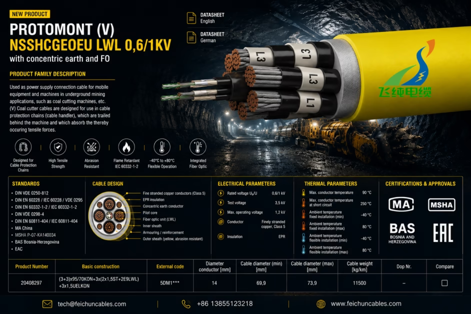
UNE 22511 High-Flexibility Underground Drag Cable
9. UNE 22511 Design Philosophy: Ultimate Flexibility for Underground Mobile Equipment
Within the taxonomy of mining cables, the distinction between the UNE 22511 and UNE 22512 standards represents a fundamental divergence in design philosophy — not merely a difference in specification parameters. Understanding this divergence is essential for engineers procuring replacement cables for underground coal mines in Spain, Chile, Colombia, and other markets operating under the AENOR (Asociación Española de Normalización y Certificación) regulatory framework.
The UNE 22511 standard governs cables for flexible connection of mobile underground mining machinery — the specific class of heavy-duty cable designed for equipment that moves continuously during operation: continuous miners, longwall shearers, shuttle cars, and cable reel systems. The engineering DNA of a UNE 22511 cable can be summarized in a single phrase: engineered for mechanical endurance, not for static installation security.
This philosophy manifests in every structural element of the cable: the conductor class, the insulation compound, the earth core arrangement, the absence of metallic armor, and the sheath compound selection. Each element is chosen not to maximize any single parameter but to achieve an optimal balance of torsional resilience, bending flexibility, and sheath durability under the combined mechanical loading of continuous dragging, occasional running-over by shuttle car wheels, and periodic full-tension pulling by cable reel drum systems.
10. Structural Deep-Dive: Conductor, Insulation, Earth Layout & Sheath
10.1 Conductor — IEC 60228 Class 5, Tinned or Bare
UNE 22511 mandates a Class 5 flexible stranded conductor, with individual wire diameters constrained to ensure sufficient wire count for mechanical resilience. For the most common cross-sections deployed in Spanish and Chilean underground coal mines (50–150 mm²), the specified wire count range is:
- 50 mm² Class 5: minimum 399 wires, maximum individual wire diameter 0.40 mm
- 95 mm² Class 5: minimum 475 wires, maximum individual wire diameter 0.53 mm
- 150 mm² Class 5: minimum 703 wires, maximum individual wire diameter 0.53 mm
Tinned copper (electrolytic Sn, 2–4 μm thickness) is the standard specification for underground drag cables. The rationale is two-fold: the mine environment, with its combination of humidity, methane, and H₂S (from coal oxidation), creates a corrosive atmosphere that attacks bare copper at the conductor surface; and the tinning process requires drawing the copper wire through a flux bath at elevated temperature, which provides a secondary annealing effect that further improves ductility and reduces residual drawing stress in the fine strands.
10.2 Insulation — EPR, 90°C Continuous Rating
The UNE 22511 standard specifies EPR (ethylene-propylene rubber) insulation, grade EI6 under the IEC 60502-1 material classification. This selection is technically mandatory rather than advisory, and the engineering rationale is compelling:
Underground mining equipment — particularly continuous miners and longwall shearers — operates with very high inertia loads. At startup, the motor draws 5–7× full-load current for 2–5 seconds. This transient generates significant joule heating at the conductor, with conductor temperatures potentially spiking to 120–140°C during repeated start cycles over an 8-hour shift. EPR’s continuous rating of 90°C and short-circuit rating of 250°C provides the thermal headroom that standard PVC (70°C continuous, 160°C short circuit) fundamentally cannot.
10.3 Earth Core Arrangement — The 3 × S1 + 3 × S2 Architecture
Of all the structural features that distinguish a properly engineered UNE 22511 cable from an inadequate substitute, the earth core arrangement is the most technically nuanced and the most frequently misunderstood. In standard industrial cables, the protective earth conductor is a single large core occupying a dedicated position in the cable cross-section. In UNE 22511, this arrangement is expressly prohibited for large cross-section cables. Instead, the standard requires:
Three symmetrically distributed earth cores (3×S1 + 3×S2), placed in the interstices between the three main phase conductors. Under this arrangement:
- S1 earth cores (equal in cross-section to the phase conductors / 3): Three cores of equal size, 120° apart geometrically, placed in the valleys between adjacent power cores.
- S2 earth cores (supplementary monitoring / pilot cores): Additional smaller earth cores co-located with S1 in a rotationally symmetric arrangement, used for earth fault monitoring and pilot-wire protection schemes mandatory under UNE EN 50153 (electrical protection of mining machinery).
This seemingly complex arrangement delivers three engineering benefits that justify its complexity:
- Electromagnetic symmetry: The three distributed earth conductors, spaced at 120°, create a symmetrical return path for the fault current that minimizes the net magnetic flux from the phase-earth fault loop. This dramatically reduces the induced voltage in adjacent signal cables — a critical safety concern in underground environments where proximity to detonator cables can cause unintended detonation.
- Mechanical roundness: A single large earth core creates an asymmetric cross-section that introduces eccentric bending stiffness — the cable bends more easily in one plane than another. The 3×S1 distributed architecture fills the inter-core voids to maintain a circular cross-section, ensuring uniform bending stiffness in all planes and preventing the torsional drift that would otherwise occur during dragging.
- Fault current distribution: Splitting the earth cross-section across three distributed conductors reduces the current density in each individual earth core, lowering I²R heating during a phase-earth fault event and extending the time before thermal damage would occur — providing longer time for the protection relay to operate safely.
Design Calculation Example — Earth Core Sizing (UNE 22511, 3×95 mm² main cores)
Per UNE 22511 and IEC 60502-1 adiabatic short-circuit heating formula: S_earth = (I_sc × √t) / k, where I_sc = prospective earth fault current (A), t = fault clearance time (s), k = 143 (for tinned copper, EPR insulation, 90°C operating temp).
- Typical underground mine fault current: I_sc = 8,000 A, t = 0.5 s (typical MCCB clearance)
- Required earth cross-section: S = (8,000 × √0.5) / 143 = 39.6 mm² → round up to 3 × 16 mm² (S1) = 48 mm² total distributed earth
- Single-core equivalent: Would require a 50 mm² core creating a 25% geometric asymmetry
- 3×S1 distributed: Each 16 mm² core adds symmetrically; geometric deviation <2% from circular
10.4 No Metallic Armor — The Deliberate Omission
The absence of metallic armor is not a cost-saving compromise in UNE 22511 — it is an engineering requirement. Steel wire armor (SWA, per IEC 60502-1 Type AWA) or steel tape armor (STA) provides excellent resistance to crushing and rodent attack in static installations, but introduces two failure mechanisms that are disqualifying for drag cable duty:
- Torsional stiffness: A helically applied wire armor acts as a torsional spring. In drag duty, the cable is subject to continuous random torsion as it is pulled around corners and over irregular surfaces. Each torsional cycle loads the armor wires in tension or compression beyond their elastic range, leading to individual wire fracture within 20,000–40,000 cycles — compared to the 500,000+ cycle life required of the EPR-insulated cores in an unarmored UNE 22511 cable.
- Catastrophic bending failure: At the minimum dynamic bending radius required for shuttle car cable reel duty (typically 4–6× outer diameter), the outer fiber of an armored cable exceeds the armor wire yield strain. Repeated cycling at this radius causes progressive armor wire fracture; when sufficient wires break, the remaining intact wires create stress concentrations that rapidly propagate failure into the EPR insulation cores beneath.
10.5 Outer Sheath — Heavy-Duty CPE or PCP
The UNE 22511 sheath is specified as Type EM7 (polychloroprene / PCP) or Type EM8 (CPE) under IEC 60502-1 material classification — the “heavy-duty” grades of each elastomer, with tensile strength ≥ 10 N/mm² and elongation ≥ 250%, compared to the ≥ 8 N/mm² / ≥ 200% standard grade. The critical performance requirements are:
- Methane resistance: The sheath must not swell or soften upon exposure to methane at concentrations up to 5% (LEL of methane in air). Both CPE and PCP satisfy this; standard PVC does not.
- Mine flame retardancy: Per UNE-EN 50265-2-2 (formerly CEI 20-35): cable must not propagate flame in a vertical tray test with a 20-kW burner applied for 20 minutes. CPE’s inherent chlorine content and PCP’s chloroprene backbone both provide this without additional halogen FR additives.
- Acid gas generation (IEC 60754-1): ≤ 0.5% HCl equivalent — the enclosed underground environment means any acid gas released during a fire event cannot be diluted by outdoor ventilation, making low acid gas generation mandatory.
- Tear resistance: ≥ 8 N/mm (measured per IEC 60811-1-1) — essential for a sheath that will be dragged over rock floor and coal fines during shuttle car operation.
11. UNE 22511 vs. UNE 22512: A Technical Differentiation Analysis
Engineers sourcing replacement cables for Spanish or Latin American mining operations frequently encounter both UNE 22511 and UNE 22512 in maintenance documentation. The two standards address fundamentally different installation scenarios, and substituting one for the other represents a serious engineering error with safety implications.
| Design Parameter | UNE 22511 (Mobile Drag Cable) | UNE 22512 (Semi-Fixed Armored) | Engineering Consequence of Error |
|---|---|---|---|
| Primary application | Continuous miners, shuttle cars, reeling equipment — continuous motion | Gate road trailing cables, semi-permanent face connections — infrequent repositioning | 22512 installed in 22511 position: armor failure in <6 months |
| Metallic armor | None — prohibited for torsional flexibility | Steel wire armor (SWA) — mandatory for crush protection in gate roads | 22511 in gate road: crushed by roof bolt rigs without armor protection |
| Min. bending radius (dynamic) | 4–6 × O.D. (cable reel / shuttle car duty) | 12–15 × O.D. (infrequent repositioning only) | 22512 on reel: armor fractures at 4–6 × O.D. bending; catastrophic failure |
| Earth core arrangement | 3×S1 + 3×S2 symmetric distributed arrangement | 1 × combined earth core (concentric or sector) | 22512 in mobile: asymmetric earth creates EMF induction hazard to detonator lines |
| Insulation compound | EPR (90°C continuous, 250°C SC) | EPR or XLPE (both acceptable) | — |
| Outer sheath | Heavy-duty CPE or PCP (EM7/EM8), no outer armor | CPE or PCP inner sheath + SWA + CPE outer sheath | — |
| Design life at full duty | 3–5 years (continuous drag) — design target per UNE 22511 | 10–15 years (semi-fixed) — lower mechanical fatigue accumulation | 22512 in 22511 position: actual life 6–18 months (armor failure driven) |
| Typical voltage rating | 1.8/3 kV and 3.6/6 kV (up to 11 kV special) | 3.6/6 kV and 6/10 kV (higher voltage gate roads) | — |
12. Benchmarking Against Nexans Eproneo Minas: Drop-in Replacement Parameters
The Nexans Eproneo Minas series is the predominant reference specification for UNE 22511 cables in Iberian and Latin American underground coal and copper mines, particularly in Chile (El Teniente, Chuquicamata underground operations) and Spain (Asturian coal basin). Feichun’s UNE 22511 series is engineered as a technically equivalent or superior alternative, with the following matched specifications:
| Technical Parameter | Nexans Eproneo Minas (Reference Specification) | Feichun UNE 22511 Series | Equivalency Status |
|---|---|---|---|
| Standard compliance | UNE 22511, IEC 60502-1 | UNE 22511, IEC 60502-1 | ✅ Fully equivalent |
| Voltage class (standard range) | 1.8/3 kV and 3.6/6 kV | 1.8/3 kV, 3.6/6 kV, 6/10 kV | ✅ Feichun adds 6/10 kV option |
| Conductor class | IEC 60228 Class 5, tinned Cu | IEC 60228 Class 5, tinned Cu | ✅ Fully equivalent |
| Insulation | EPR (EI6), 90°C / 250°C SC | EPR (EI6), 90°C / 250°C SC | ✅ Fully equivalent |
| Earth arrangement | 3×S1 + 3×S2 symmetric distributed | 3×S1 + 3×S2 symmetric distributed | ✅ Fully equivalent |
| Outer sheath compound | PCP (Neoprene), EM7 grade | PCP (EM7) standard; CPE (EM8) optional | ✅ Equivalent + CPE option |
| Mine flame retardancy | UNE-EN 50265-2-2 compliant | UNE-EN 50265-2-2 compliant | ✅ Fully equivalent |
| Acid gas generation (IEC 60754-1) | ≤ 0.5% HCl equivalent | ≤ 0.5% HCl equivalent (tested) | ✅ Fully equivalent |
| Outer diameter tolerance | ±5% of nominal O.D. | ±5% of nominal O.D. | ✅ Drop-in dimensional compatibility |
| Typical lead time (standard sizes) | 8–16 weeks (EU manufacturing) | 4–8 weeks (Hefei, China manufacturing) | ✅ Faster supply to South America / Asia |
| Cost vs. Nexans (estimated, ex-works) | Index 1.0× | 0.55–0.70× (30–45% lower) | ✅ Significant OPEX reduction |
13. Mechanical Endurance: Torsion, Tensile & Bending Cycle Analysis
The mechanical endurance of a UNE 22511 cable is not a single-axis property — it is the result of a multi-axis loading regime that the cable must survive simultaneously. Feichun’s testing protocol for UNE 22511 qualification addresses three independent failure modes:
13.1 Torsional Endurance Test (DIN VDE 0295 / IEC 60811-503)
The cable is subjected to ±180° rotation per meter of free length (representative of shuttle car maneuvering around a face corner), repeated for 10,000 cycles. A passing cable shows:
- No visual sheath cracking or peeling
- No conductor resistance increase >1% (indicating no strand fracture)
- No reduction in insulation resistance below IEC 60502-1 minimum (100 MΩ·km)
13.2 Tensile Cycle Endurance
Cable reeling systems on continuous miners apply cyclic tensile loads of 200–1,200 N (depending on cable diameter and reel geometry). Feichun tests UNE 22511 cables to 50,000 cycles at 30% of rated tensile load (approximately 0.6–2.4 kN for 50–150 mm² cables), confirming structural integrity of the conductor-sheath interface.
13.3 Combined Bending-Torsion Fatigue (Shuttle Car Simulation)
The most destructive real-world loading condition is combined bending at the cable drum anchor point while the free length is simultaneously under torsional load. Feichun’s proprietary shuttle car simulation test applies 500,000 combined bending-torsion cycles at 6× O.D. bending radius with ±90° torsion — this is the most demanding test in the qualification program and is specific to the UNE 22511 drag cable application.
14. Mining Compliance: Flame Retardancy, Gas Generation & Regulatory Framework
Underground mining cables in Spain, Chile, and other UNE-adopting markets must satisfy a multi-layered regulatory framework that extends significantly beyond the electrical performance requirements of IEC 60502-1. Feichun’s UNE 22511 series is qualified to the following regulatory requirements:
- UNE 22511 (structural and electrical requirements): The defining standard; full compliance confirmed by third-party AENOR-accredited laboratory testing.
- UNE-EN 50265-2-2 (IEC 60332-2-2 equivalent): Vertical flame propagation test: 20-minute burner at 20 kW; cable may not propagate flame beyond 2.5 m above burner. Both CPE and PCP sheath grades qualified.
- IEC 60754-1: Acid gas generation during combustion: ≤ 0.5% HCl equivalent measured by pH of combustion gas condensate. Essential for enclosed underground environments where acid gas cannot be ventilated.
- IEC 61034-2: Smoke density during combustion: Optical density ≤ 60% measured in 3 m³ test chamber at peak combustion. Low smoke density is critical for emergency evacuation visibility in underground access tunnels.
- Chilean Ley N° 16.744 (Mining Safety Law) & DS N° 132/2004 (Mining Safety Regulations): Chilean operations additionally require compliance with these national mining safety statutes. Feichun provides full technical documentation package (type test reports, third-party certificates) to support customer authorization submissions to the Chilean Servicio Nacional de Geología y Minería (SERNAGEOMIN).
- UNE-EN 50153 (Railway and mining electrical protection): The earth fault monitoring system enabled by the S2 earth cores must meet the response time and sensitivity requirements of UNE-EN 50153 for personnel protection. Feichun provides S2 pilot core resistance values and continuity test protocol documentation for commissioning engineers.


