R-7 PUR Round Reeling Cable for High-Performance Cable Reel Systems. Resilient Polyurethane Cable Designed for Spring and Motorized Cable Reels with Superior Torsional Rigidity

Understanding the 12YRDT11Y11Y Cable: R-7 PUR Round Reeling Cable for High-Performance Cable Reel Systems
The 12YRDT11Y11Y cable, also known as the R-7 PUR round reeling cable, represents a specialized engineering solution for cable reel systems in demanding industrial environments. Distinguished by its distinctive yellow outer sheath and advanced construction featuring a supportive mesh vulcanized between inner and outer sheaths, this cable delivers exceptional torsional rigidity essential for both spring-driven and motorized cable reels used in crane systems, hoisting equipment, and material handling applications.
1. What is the 12YRDT11Y11Y Cable?
The 12YRDT11Y11Y is a highly resilient PUR (polyurethane) round cable specifically engineered for use on cable reels where cables must withstand the combined stresses of tension, bending, and torsion during continuous winding and unwinding operations. This cable is classified as Category 5 flexible according to DIN VDE 0295, providing an optimal balance between flexibility and structural integrity for reeling applications.
Cable Designation Decoded
- 12Y – Core insulation based on polyester (PE)
- RDT – Round cable for use on reels (Reel Drum Type)
- 11Y – Inner sheath based on PUR (polyurethane)
- 11Y – Outer sheath PUR (wear-resistant, halogen-free, yellow)
What sets this cable apart from standard flexible cables is its unique three-layer construction with a supportive braid vulcanized between the inner and outer sheaths. This reinforcement mesh provides exceptional torsional rigidity, preventing cable twist and ensuring stable performance during high-cycle reeling operations.
Distinctive Yellow Identification
The cable features a bright yellow outer sheath that provides high visibility in industrial environments and is a standard color for reeling cables, making them easily identifiable and distinguishable from other cable types during installation and maintenance.
2. Purpose and Applications
Primary Application: Cable Reel Systems
The 12YRDT11Y11Y cable is specifically designed for cable reel applications, which are mobile power supply systems used to deliver electrical power to moving equipment. Cable reels are particularly advantageous when:
- A continuous power source is required for moving machinery
- Travel distances are significant but manageable (typically up to 100+ meters)
- The application requires centralized power distribution
- Space constraints make festoon systems impractical
- The installation environment permits adequate space for the reel housing
Spring vs. Motor-Driven Cable Reels
Spring-Driven Reels: Utilize mechanical spring tension to automatically retract cable. Ideal for lighter duty applications, shorter travel distances, and equipment without external power supply. Cost-effective and low maintenance.
Motor-Driven Reels: Employ electric motors with torque control to wind cable synchronously with equipment movement. Suitable for heavy-duty applications, longer distances, higher cable weights, and high-speed operations. Provide precise cable tensioning and longer service life.
Secondary Application: Energy Guiding Chains
While optimized for cable reels, the 12YRDT11Y11Y can also serve as a secondary application in energy guiding chains where its torsional rigidity and compact structure provide benefits in applications with rotational components or where cable twist prevention is critical.
Typical Industrial Applications
Material transfer vehicles in manufacturing facilities
Small to medium hoisting heights (typically up to 50m)
Sewage treatment plant equipment
Mobile stage equipment and theatrical rigging
Automated material handling equipment
Indoor and outdoor gantry crane systems
3. Key Characteristics and Features
High Torsional Rigidity
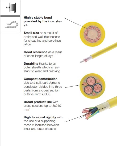
Supportive mesh vulcanized between inner and outer sheaths provides exceptional resistance to twisting forces during winding and unwinding cycles.
Compact Construction
Optimized wall thicknesses for sheathing and core insulation result in smaller overall diameter compared to traditional reeling cables, enabling selection of more compact and cost-effective reel systems.
Superior Durability
Wear-resistant and crack-resistant PUR outer sheath withstands continuous abrasion against the reel drum surface and environmental stresses.
Split Earth Conductor Design
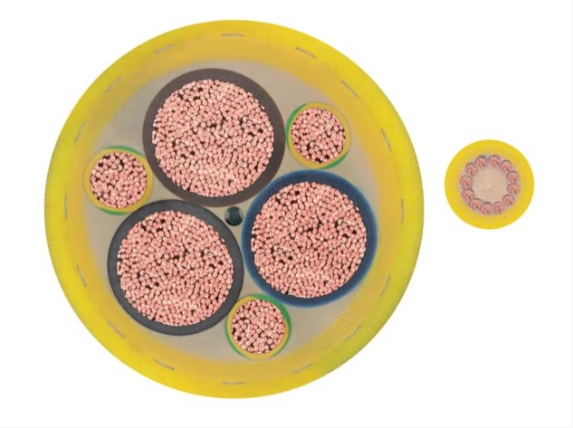
From cross-sections of 3×25mm² + 3G6 and above, the earth/ground conductor is divided into three parts, ensuring compact construction while maintaining safety grounding.
Wide Temperature Range
Operational from -20°C to +70°C during flexing, with extended range to -30°C to +70°C for fixed installations.
Highly Stable Bond
Inner protective sheath creates exceptional bonding between cable layers, preventing layer separation during repetitive bending and torsion.
Short Lay Length
Good resilience achieved through short length of lays in the stranding design, optimizing flexibility while maintaining structural integrity.
Broad Product Range
Available in cross-sections from 7×1.5mm² up to 3×240mm² + 3G50, covering control cables, power cables, and combined configurations.
Cost-Effective Solution
The 12YRDT11Y11Y cable is engineered as a cost-effective solution for applications where small to medium dynamic loads act on the system. While it may not have the extreme flexibility of Category 6 cables, it provides an optimal balance of performance and economy for standard cable reel applications where budget considerations are important.
4. Material Structure and Design
Multi-Layer Construction
The 12YRDT11Y11Y cable employs a sophisticated multi-layer design that balances flexibility, durability, and torsional stability:
| Layer | Material | Function |
|---|---|---|
| Conductor | Bare electrolytic copper, flexible Category 5 (DIN VDE 0295) | Electrical transmission with good flexibility |
| Core Insulation | Special polymer (polyester base) | Electrical insulation with stable dielectric properties |
| Central Reinforcement | Textile element (strength member) | Tensile load distribution and structural support |
| Inner Sheath | Polyurethane (PUR) over filler | Layer bonding and mechanical protection |
| Supportive Braid | Textile mesh (vulcanized) | Torsional rigidity and twist prevention |
| Outer Sheath | Wear-resistant polyurethane (PUR), halogen-free, yellow | Abrasion resistance, environmental protection, visibility |
The Critical Role of the Supportive Mesh
The supportive braid vulcanized between the sheaths is the key differentiator of this cable design. This reinforcement layer:
- Provides high torsional rigidity to prevent cable rotation during winding
- Maintains circular cross-section under bending stress
- Distributes mechanical forces evenly across the cable structure
- Prevents “telescoping” (axial displacement of layers) during flexing
- Extends cable service life by reducing stress on conductors and insulation
Conductor Construction
The cable utilizes flexible Category 5 conductors according to DIN VDE 0295. While not as flexible as Category 6 conductors used in energy chain cables, Category 5 provides sufficient flexibility for reeling applications while offering:
- Lower manufacturing cost compared to Category 6
- Adequate flexibility for 8× cable diameter bending radius
- Good electrical performance with lower DC resistance
- Suitable service life for typical reeling duty cycles
Stranding Design
The cable cores are stranded in layers with a layered construction that provides:
- Good space utilization for compact overall diameter
- Balanced construction preventing cable rotation
- Uniform flexibility across all bending planes
- Stable electrical and mechanical properties
Color Coding System
Conductor identification follows DIN VDE 0293, part 308:
- Up to 5 conductors: Colored insulation (brown, black, grey, blue, green/yellow)
- 6 or more conductors: Black cores with white numbering
- Protective conductor: Green/yellow (where applicable)
- Outer sheath: Yellow (standard for reeling cables)
Split Earth Conductor Configuration
For power cables from 3×25mm² + 3G6 and larger, the earth conductor is divided into three parts (3G configuration). This innovative design:
- Reduces overall cable diameter by 15-20% compared to single earth conductor
- Maintains equivalent or better grounding performance through parallel conductors
- Improves cable flexibility and reduces bending stiffness
- Enables use of smaller, more economical cable reel systems
5. Standards Compliance
Primary Standards
The 12YRDT11Y11Y cable is manufactured adapted to DIN VDE 0250, the German national standard for cables, wires, and flexible cords for power installations. This standard is globally recognized as the definitive specification for crane and reeling cables.
| Standard | Compliance Aspect |
|---|---|
| DIN VDE 0250 | Overall cable construction, materials, and performance requirements for power installation cables |
| DIN VDE 0295 | Conductor construction – Category 5 flexible conductors with specified stranding and resistance |
| DIN VDE 0293 Part 308 | Conductor color coding and identification system |
| DIN VDE 0298 Part 4 | Current-carrying capacity calculation methods and ampacity derating factors |
| DIN VDE 0482 / IEC 60332-1 | Flame retardant and self-extinguishing properties under fire conditions |
Important Note: Halogen Content
Unlike the 11YMSL11Y series, the 12YRDT11Y11Y cable is NOT fully halogen-free. While the outer PUR sheath is halogen-free, the core insulation materials may contain halogens. This is important to consider for applications where halogen-free properties are mandatory, such as:
- Indoor installations in public buildings
- Installations near sensitive electronic equipment
- Applications where low smoke and fume generation is critical
- Installations subject to specific fire safety regulations requiring halogen-free cables
For applications requiring fully halogen-free cables, alternative products should be considered.
Fire Performance Characteristics
- Flame Retardant: Meets DIN VDE 0482 part 265-2-1 requirements
- Self-Extinguishing: Complies with IEC 60332-1 vertical flame test
- Limited Fire Propagation: Will not sustain combustion when flame source is removed
Environmental Resistance
- Resistant to ozone and atmospheric oxidation
- Resistant to humidity and moisture (not submersible)
- UV-resistant for outdoor applications
- Oil-resistant for industrial environments
- LBS-free / Silicone-free (prevents contamination in sensitive processes)
6. Safety Thresholds and Technical Parameters
Electrical Safety Specifications
| Parameter | Value | Notes |
|---|---|---|
| Rated Voltage (Uo/U) | 600/1000V (0.6/1 kV) | All conductor sizes |
| Maximum AC Operating Voltage | 700/1200V | Continuous operation limit |
| Maximum DC Operating Voltage | 900/1800V | Continuous operation limit |
| AC Test Voltage | 2.5 kV | Type testing requirement |
Thermal Operating Parameters
| Condition | Temperature Range | Application Context |
|---|---|---|
| Flexing Operation | -20°C to +70°C | Moving applications on cable reels |
| Fixed Installation | -30°C to +70°C | Stationary cable sections |
| Maximum Conductor Temperature | 90°C | Continuous operation at rated ampacity |
| Short-Circuit Temperature | 250°C | Maximum 5 seconds (higher than Category 6 cables) |
⚠️ Temperature Operating Window
The flexing temperature range of -20°C to +70°C is narrower than the 11YMSL11Y series (-30°C to +80°C). This cable is not suitable for:
- Arctic or extreme cold environments below -20°C
- High-temperature applications exceeding +70°C ambient
- Direct sunlight exposure in desert climates where surface temperatures may exceed 70°C
For applications outside this range, alternative cable types should be specified.
Mechanical Performance Limits
| Parameter | Specification | Significance |
|---|---|---|
| Minimum Bending Radius | 8 × cable diameter | For reeling applications (larger than energy chain cables) |
| Travel Speed | Up to 100 m/min (standard) | >100 m/min available on request |
| Tensile Load Capacity | 20 N/mm² | Higher than Category 6 cables (15 N/mm²) |
| Permitted Tensile Load | Varies by cable size | Range: 200N (4G2.5) to 14,400N (3×240+3G50) |
Ampacity Calculation Basis
The published ampacity values are calculated based on specific conditions that differ from energy chain cables:
- Ambient temperature: 30°C
- Installation method: Monospiral reel coil (single layer winding)
- Duty cycle: 100% (continuous operation)
- Heat dissipation: Free air convection from reel surface
Ampacity Derating for Cable Reels
Cable reels present unique thermal challenges:
- Multi-layer winding: Inner layers have poor heat dissipation; derating factors of 0.6-0.8 may apply
- Continuous operation: Heat accumulation in wound cable requires conservative ampacity selection
- Ambient temperature: Outdoor reels in direct sunlight may experience 50-60°C ambient
- Reel size: Larger diameter reels provide better heat dissipation
Recommendation: Consult cable manufacturer for specific ampacity calculations based on reel design, layer count, and operating duty cycle. Conservative derating (50-60% of published values) is often appropriate for multi-layer reels with continuous operation.
7. Precautions for Use and Installation
Cable Reel Selection and Sizing
Critical Reel Sizing Requirements
- Drum diameter: Minimum drum diameter must be at least 16× cable outer diameter to maintain 8× bending radius
- Flange capacity: Reel flanges must accommodate full cable length plus 20% safety margin
- Weight capacity: Reel structure must support total cable weight plus dynamic loads during operation
- Winding capacity: Calculate required winding layers and apply appropriate ampacity derating
Installation Best Practices
- Cable Attachment to Reel Drum:
- Use proper cable clamp or anchor system that distributes strain evenly
- Ensure attachment point does not exceed cable’s tensile load rating
- Position first wrap to prevent cable damage at drum surface
- Leave adequate service loop for electrical termination
- Winding Direction and Layering:
- Maintain consistent winding direction throughout installation
- Ensure even layer formation with no gaps or overlaps
- Use level-wind mechanism for neat winding in motorized systems
- Apply appropriate tension during winding to prevent loose coils
- Slip Ring Connection:
- Cable must transition from reel to slip ring assembly or collector
- Provide adequate strain relief at this critical junction
- Ensure proper alignment to prevent cable abrasion
- Verify slip ring current rating exceeds cable ampacity
- Cable Guiding and Support:
- Install cable guide roller or arm to maintain proper spooling
- Position guide to ensure 90° cable entry to reel drum
- Support cable between reel and moving equipment to prevent excessive sagging
- Use cable guide sheaves where direction changes are required
Spring Cable Reel Specific Considerations
- Spring tension adjustment: Set spring tension to match cable weight and length
- Over-tension prevention: Ensure spring cannot over-retract and damage cable
- Ratchet mechanism: Verify lock-out feature functions properly if required
- Maximum extension: Do not exceed rated cable extension to prevent spring failure
Motorized Cable Reel Specific Considerations
- Motor synchronization: Program motor controller to match equipment travel speed
- Torque control: Set appropriate torque limits to prevent cable damage
- Encoder feedback: Install and calibrate position encoder for precise winding
- Emergency stop: Implement emergency stop function tied to crane safety system
- Limit switches: Configure end-of-travel limits to prevent over-spooling
Environmental Considerations
- Outdoor installations: Protect reel and cable from direct sunlight and precipitation where possible
- Contamination: Shield cable from industrial dust, metal chips, and chemical splashes
- Moisture: Ensure electrical connections are properly sealed and weatherproof
- Temperature monitoring: Install temperature sensors for critical high-current applications
Electrical Safety Precautions
⚡ Critical Electrical Safety
- De-energize system and implement lockout/tagout before any maintenance
- Verify proper grounding of equipment frame and reel structure
- Install appropriate overcurrent protection sized to cable ampacity
- Use ground fault protection for enhanced safety
- Ensure slip ring brushes are properly maintained and make consistent contact
- Inspect electrical connections regularly for signs of overheating or corrosion
Handling and Storage
- Storage conditions: Store in dry location at 0°C to +40°C
- Reel storage: Keep cable on original reel or properly sized storage reel
- UV protection: Cover stored cable to prevent UV degradation of yellow sheath
- Shelf life: Use within 2-3 years of manufacture for optimal performance
8. Common Problems and Solutions
Problem 1: Cable Twisting on Reel (Loss of Torsional Control)
Symptoms: Cable develops twist along its length, uneven winding on reel, cable binds during unwinding
Causes:
- Improper cable guide alignment causing off-axis spooling
- Incorrect spring tension (too tight or too loose)
- Damaged supportive mesh from excessive bending or impact
- Cable wound onto reel with pre-existing twist
Solutions:
- Verify cable guide maintains 90° entry angle to drum across full travel
- Adjust spring tension or motor torque settings to manufacturer specifications
- Inspect cable for damage; replace if supportive mesh integrity is compromised
- Remove cable completely and rewind ensuring no twist is introduced
- The supportive mesh design should prevent twisting when properly installed
Problem 2: Overheating During Continuous Operation
Symptoms: Cable sheath feels excessively hot, reduced service life, insulation degradation, tripping of thermal overloads
Causes:
- Operating current exceeds derated ampacity for multi-layer winding
- Poor heat dissipation from inner cable layers on reel
- Ambient temperature near or exceeding +70°C limit
- Continuous 100% duty cycle without adequate cooling periods
Solutions:
- Measure actual operating current and compare to properly derated ampacity
- Increase conductor size to reduce current density and heat generation
- Modify operating duty cycle to allow cooling periods
- Increase reel diameter to improve heat dissipation
- Add forced ventilation (fan cooling) for the reel in enclosed spaces
- Consider thermal imaging inspection to identify hot spots
Problem 3: Premature Outer Sheath Wear
Symptoms: Abrasion marks on yellow sheath, sheath cracking or splitting, exposed inner layers
Causes:
- Cable rubbing against reel flange during winding
- Rough drum surface or sharp edges on reel
- Contamination with abrasive particles (sand, metal chips)
- Excessive bending at cable entry point to reel
Solutions:
- Adjust cable guide to prevent cable contact with flange
- Inspect and smooth any rough spots on drum surface
- Install drum liner (rubber or polyurethane) to protect cable
- Clean reel regularly to remove abrasive contaminants
- Verify minimum bending radius (8× diameter) is maintained
- Consider installing cable protection sleeve at high-wear points
Problem 4: Cable Bird-Caging (Conductor Deformation)
Symptoms: Cable diameter increases locally, conductors visible through sheath distortion, stiff sections in cable
Causes:
- Excessive tensile load exceeding 20 N/mm² rating
- Impact damage during installation or operation
- Repeated severe bending below minimum radius
- Cable crushed under heavy weight (multi-layer reel loading)
Solutions:
- Verify cable is not subjected to shock loads or sudden jerks
- Install shock absorbers or buffer systems in equipment motion system
- Ensure even winding tension prevents crushing of lower layers
- Replace damaged cable sections; bird-caging damage is not repairable
- Review equipment motion profiles for acceleration/deceleration limits
Problem 5: Slip Ring Connection Failure
Symptoms: Intermittent power loss, sparking at slip ring, brush wear acceleration, connection overheating
Causes:
- Poor strain relief at cable-to-slip ring junction
- Cable movement causing connection loosening
- Inadequate slip ring current rating
- Corrosion or contamination of slip ring surfaces
Solutions:
- Install proper strain relief device rated for cable weight and motion
- Verify all terminations are tight and properly crimped or soldered
- Clean slip ring surfaces and replace worn brushes
- Upgrade to higher-capacity slip ring assembly if undersized
- Apply appropriate contact lubricant to slip ring surfaces
- Consider enclosed slip ring design for contaminated environments
Problem 6: Spring Reel Failure to Retract
Symptoms: Cable does not retract or retracts slowly, spring mechanism jammed or broken
Causes:
- Spring fatigue from excessive cycles or overloading
- Cable weight exceeds reel capacity
- Mechanical jamming from debris or misalignment
- Frozen mechanism in cold environments
Solutions:
- Inspect spring mechanism; replace spring assembly if damaged
- Verify cable weight is within reel’s rated capacity
- Clean and lubricate reel mechanism according to manufacturer schedule
- For cold environments, use low-temperature grease and consider heating elements
- Consider upgrading to motorized reel for heavier cable or higher duty cycle
Preventive Maintenance Schedule
| Interval | Inspection Items | Action |
|---|---|---|
| Daily | Visual inspection during operation | Observe winding pattern, listen for unusual sounds, check for vibration |
| Weekly | Detailed cable inspection | Check sheath condition, verify proper winding, inspect slip ring connections |
| Monthly | Mechanical system check | Lubricate reel bearings, test limit switches, verify spring/motor operation |
| Quarterly | Electrical testing | Insulation resistance test, continuity check, slip ring brush inspection |
| Semi-Annually | Cable unspooling inspection | Completely unspool cable to inspect full length for damage |
| Annually | Comprehensive system evaluation | Full electrical and mechanical assessment, replace worn components |
9. Conclusion
The 12YRDT11Y11Y Cable (R-7 PUR round reeling cable) represents a purpose-engineered solution for cable reel applications in industrial environments. Manufactured by Anhui Feichun Special Cable Co., Ltd., this cable incorporates specialized design features including a supportive mesh vulcanized between sheaths for superior torsional rigidity, optimized wall thicknesses for compact construction, and a distinctive yellow outer sheath for high visibility.
Key Advantages Summary
- Cost-Effective Design: Balanced performance and economy for standard reeling applications
- Torsional Stability: Reinforced construction prevents cable twist during winding cycles
- Compact Dimensions: Reduced diameter enables smaller, more economical reel systems
- Broad Application Range: Suitable for spring and motorized reels in diverse industries
- Durable Construction: Wear-resistant PUR sheath provides long service life
- Wide Product Range: Available from 7×1.5mm² to 3×240mm² + 3G50 configurations
This cable is ideally suited for applications involving:
- Small to medium dynamic loads with travel speeds up to 100 m/min
- High tension, bending, and torsional forces inherent in reeling operations
- Operating temperatures from -20°C to +70°C during flexing
- Cost-sensitive projects requiring reliable performance without premium pricing
- Compact reeling systems where cable diameter is a critical constraint
Selection Considerations
The 12YRDT11Y11Y is optimal when:
- Cable reel is the primary power delivery method
- Torsional rigidity is more important than extreme flexibility
- Operating environment is within -20°C to +70°C range
- Halogen-free properties are not mandatory
- Bending radius of 8× cable diameter is acceptable
- Budget constraints favor Category 5 over Category 6 conductor flexibility
When properly selected, installed, and maintained according to the guidelines in this article, the 12YRDT11Y11Y cable delivers reliable, long-term performance in cable reel applications. The unique supportive mesh construction and optimized material selection provide the torsional stability and durability essential for continuous reeling duty cycles in industrial environments.
Contact Anhui Feichun Special Cable Co., Ltd.
For technical inquiries, cable selection assistance, or to place an order for 12YRDT11Y11Y reeling cables:
Email: [email protected]
International Sales: +86 13855123218
References and Further Reading
- DIN VDE 0250 – Cables, wires and flexible cords for power installations
- DIN VDE 0295 – Conductors of cables and cords
- DIN VDE 0293 – Core identification for cables and flexible cords
- DIN VDE 0298 Part 4 – Current-carrying capacity calculations
- Overhead Lifting. (April 2023). “Crane Electrification Options: Conductor Bars, Festoons, And Cable Reels.” Link
- VAHLE. “Motor Powered Cable Reels.” Link
- Stemmann-Technik. “Motor-Driven Cable Reels.” Link
- Nante Crane. “Cable Reel Components.” Link
- Konecranes. “Cable Reel Power Options for RTGs.” Link
- Tullyn Trading. “Trommelflex PUR-HF Reeling Cable Technology.” Link