
A Deep Dive into Grounding System Architecture, Partial Discharge Risk Assessment, Insulation Thickness Selection, and Practical Guidance for Offshore Platform and Vessel Electrical Design
Type MMV 15kV 船用电缆中 100% 与 133% 绝缘等级的深度解析——接地系统架构、局放风险评估、绝缘厚度选择与海上平台船舶电气设计实践指南
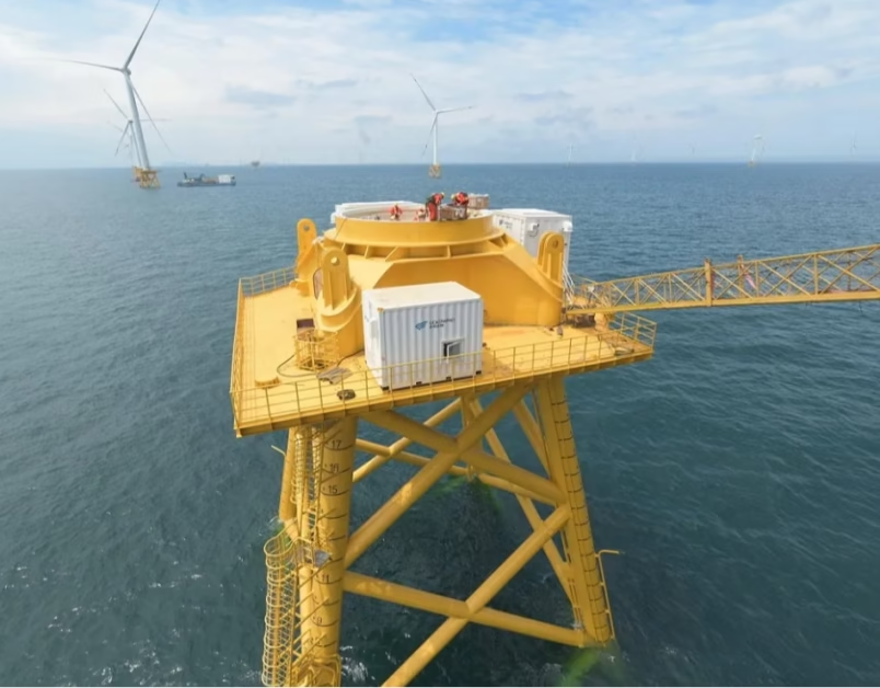
Understanding 100% vs. 133% Insulation Levels in Type MMV 15kV Marine Cables
A Deep Dive into Grounding System Architecture, Partial Discharge Risk Assessment, Insulation Thickness Selection, and Practical Guidance for Offshore Platform and Vessel Electrical Design
Type MMV 15kV 船用电缆中 100% 与 133% 绝缘等级的深度解析——接地系统架构、局放风险评估、绝缘厚度选择与海上平台船舶电气设计实践指南
1. The Mystery of 100% and 133%: Why Insulation Levels Matter
When a marine electrical engineer opens a cable specification document for a 15 kV Type MMV cable, among the first technical parameters to be scrutinized is the notation of insulation level: either 100% or 133%. To the uninitiated, these seemingly abstract percentages might appear to be arbitrary marketing designations. In reality, they represent a profound engineering distinction rooted in power system grounding philosophy and the way electrical stress distributes across the cable insulation during both normal operation and fault conditions. Understanding this distinction is essential for anyone responsible for specifying cables for offshore platforms, FPSOs, or dynamic positioning vessels, because choosing the wrong insulation level can result in premature cable failures, cascading electrical faults, and operational disasters.
当海洋电气工程师打开 15 kV Type MMV 电缆的规格文档时,首先要审查的技术参数之一是绝缘等级的标记:100% 或 133%。对于不熟悉的人来说,这些看似抽象的百分比可能显得是任意的营销名称。实际上,它们代表了植根于电力系统接地哲学和在正常运行和故障条件下电应力如何分布在电缆绝缘中的深刻工程区别。理解这种区别对于任何负责为海上平台、FPSO 或动态定位船舶指定电缆的人来说都是必不可少的,因为选择错误的绝缘等级可能导致电缆过早失效、电气故障级联和运营灾难。
To build a proper understanding of these insulation levels, we must first establish the foundational concept: what is an insulation level, and why does it exist at all? At its core, an insulation level is a specification of the maximum voltage that the cable insulation can safely withstand during both normal steady-state operation and during transient overvoltage conditions. These transient overvoltages arise from various sources: lightning strikes, switching operations in the electrical switchboard (opening or closing large circuit breakers), equipment failures, or phase-to-ground faults. The cable insulation must have sufficient thickness and material quality to survive these transient stresses without suffering permanent damage through partial discharge, insulation perforation, or thermal degradation.
为了建立对这些绝缘等级的适当理解,我们必须首先建立基本概念:绝缘等级是什么,为什么它存在?从根本上讲,绝缘等级是电缆绝缘在正常稳态运行和瞬时过电压条件下都能安全承受的最大电压的规范。这些瞬时过电压来自各种来源:雷击、电气开关柜的开关操作(打开或关闭大型断路器)、设备故障或相对地故障。电缆绝缘必须有足够的厚度和材料质量,以在这些瞬时应力中存活,而不通过局部放电、绝缘穿孔或热降解遭受永久性损伤。
Before we can understand insulation levels, we must clarify voltage terminology. When we say a cable is rated 8.7/15 kV (which is the standard voltage designation for Type MMV cables in this article), we are using a nomenclature that specifies two voltage values. The first number, 8.7 kV, is the nominal phase-to-ground voltage of the power system (also called the working voltage). The second number, 15 kV, is the maximum phase-to-phase voltage of the system (also called the rated voltage or nominal system voltage). In a three-phase balanced system, the relationship between these is straightforward: if the phase-to-ground voltage is 8.7 kV, then the phase-to-phase voltage is 8.7 × √3 ≈ 15 kV. This nomenclature is standard across IEC 60092, IEEE 1580, and all major maritime electrical standards. Now, when we speak of insulation levels expressed as percentages, we are referring to the maximum voltage that the insulation can withstand as a percentage of the nominal system voltage (the phase-to-ground voltage).
在我们能够理解绝缘等级之前,我们必须澄清电压术语。当我们说电缆额定 8.7/15 kV(这是本文中 Type MMV 电缆的标准电压指定)时,我们使用的命名法指定了两个电压值。第一个数字 8.7 kV 是电力系统的标称相对地电压(也称为工作电压)。第二个数字 15 kV 是系统的最大相对相电压(也称为额定电压或标称系统电压)。在三相平衡系统中,这些之间的关系很简单:如果相对地电压是 8.7 kV,那么相对相电压是 8.7 × √3 ≈ 15 kV。这种命名法在 IEC 60092、IEEE 1580 和所有主要海事电气标准中都是标准的。现在,当我们谈论绝缘等级表示为百分比时,我们指的是绝缘能够承受的最大电压,作为标称系统电压(相对地电压)的百分比。
2. Understanding Grounding System Design and Its Role
To understand why 100% and 133% insulation levels exist, we must first understand the fundamental question that every electrical system designer must answer: How should the neutral point of the power system be connected to ground? This seemingly esoteric question has profound implications for cable insulation design, protection coordination, and system reliability.
要理解为什么存在 100% 和 133% 绝缘等级,我们必须首先理解每个电气系统设计者必须回答的基本问题:电力系统的中性点应如何连接到地?这个看似深奥的问题对电缆绝缘设计、保护协调和系统可靠性具有深远的含义。
2.1 Solidly Grounded Systems
A solidly grounded system is one where the neutral point (the center point of the three-phase winding in the power transformer or generator) is connected directly to ground through a metallic conductor with negligible impedance. When a phase conductor accidentally makes contact with the ship’s hull or equipment frame (a phase-to-ground fault), a very large current flows immediately through the low-impedance ground path, activating protective relays and circuit breakers to isolate the faulted section within milliseconds. During this fault condition, the voltage seen by the unfaulted phases rises, but the rise is limited and predictable. In a three-phase system with one phase faulted to ground, the two unfaulted phases experience a voltage rise to approximately 115% to 120% of the normal phase-to-ground voltage. This is the physical origin of the 100% insulation level specification: it provides adequate safety margin (insulation thickness sufficient to withstand 100% of the normal phase-to-ground voltage) during normal operation and transient overvoltages in a solidly grounded system.
牢固接地系统是指中性点(电力变压器或发电机三相绕组的中心点)通过具有可忽略阻抗的金属导体直接连接到地的系统。当相导体意外与船的船体或设备框架接触(相对地故障)时,大的电流立即通过低阻抗接地路径流动,激活保护继电器和断路器在毫秒内隔离故障部分。在这种故障条件下,无故障相看到的电压上升,但上升是有限且可预测的。在三相系统中,一相接地故障时,两个无故障相经历的电压上升到约 115% 至 120% 的正常相对地电压。这是 100% 绝缘等级规范的物理起源:它在牢固接地系统中的正常运行和瞬时过电压期间提供充分的安全裕度(绝缘厚度足以承受 100% 的正常相对地电压)。
2.2 Ungrounded and High-Impedance Grounded Systems
An ungrounded system (sometimes called a floating system) is one where the neutral point is deliberately isolated from ground. This design choice is often made in offshore applications where system continuity is critical: if a single phase-to-ground fault occurs in an ungrounded system, no large fault current flows. The system can continue to operate safely even with one phase partially faulted, allowing time for crew to locate and repair the fault without causing an emergency shutdown of critical equipment like dynamic positioning thrusters or main propulsion. However, this operational flexibility comes with a critical thermal consequence: without a low-impedance ground path, the voltage rise on the unfaulted phases during a ground fault becomes much more severe. In an ungrounded system with a phase-to-ground fault, the two unfaulted phases can experience a voltage rise to nearly 190% to 200% of the normal phase-to-ground voltage—a phenomenon called the ground-fault overvoltage. This extreme voltage rise is the reason that ungrounded systems require significantly thicker cable insulation: the cable insulation must safely withstand this transient overvoltage without breakdown. This is the physical origin of the 133% insulation level: it provides sufficient thickness to safely withstand the transient overvoltages that arise in ungrounded and high-impedance grounded systems.
非接地系统(有时称为浮动系统)是中性点故意与地隔离的系统。这种设计选择经常在需要系统连续性至关重要的海上应用中进行:如果在非接地系统中发生相对地故障,没有大的故障电流流动。系统即使有一相部分故障也可以继续安全运行,允许时间让船员定位和修复故障,而不会导致动态定位推进器或主推进等关键设备的紧急关闭。然而,这种运营灵活性伴随着一个关键的热后果:没有低阻抗接地路径,地故障期间无故障相的电压上升变得更严重。在具有相对地故障的非接地系统中,两个无故障相可能经历的电压上升到几乎 190% 至 200% 的正常相对地电压——这一现象称为接地故障过电压。这种极端的电压上升是非接地系统需要明显更厚的电缆绝缘的原因:电缆绝缘必须安全地承受这种瞬时过电压而不破裂。这是 133% 绝缘等级的物理起源:它提供足够的厚度以安全地承受在非接地和高阻抗接地系统中出现的瞬时过电压。
Let us work through a concrete example to solidify this understanding. Consider a 15 kV Type MMV three-phase power system (nominal phase-to-ground voltage of 8.7 kV). Under normal steady-state operation, each phase conductor carries a sinusoidal voltage with peak amplitude of 8.7 kV × √2 ≈ 12.3 kV above the ship’s hull. Now imagine a single-phase-to-ground fault occurs on Phase A, and the fault resistance is very low (essentially a dead short to ground). In a solidly grounded system, the neutral point is connected directly to ground, so the neutral voltage remains very close to the hull ground potential (zero volts). When Phase A shorts to ground, the fault current flows directly through the neutral return, circuit breaker opens, and the fault is cleared. During this transient, Phase B (which was at 8.7 kV relative to ground) experiences a temporary voltage rise. Using three-phase voltage relationships, when one phase is faulted, the unfaulted phases experience a voltage equal to the line voltage divided by √3, which works out to approximately 8.7 × 1.15 = 10 kV, or about 115% of the normal phase-to-ground voltage. The insulation designed for 100% of 8.7 kV (i.e., 8.7 kV insulation thickness) thus has about 15% safety margin against this 10 kV transient. This is deemed acceptable by electrical standards because the circuit breaker acts very quickly, and the transient duration is extremely brief (typically less than 100 milliseconds). Now contrast this with an ungrounded system. When Phase A faults to ground in an ungrounded system, there is no low-impedance neutral return path. Instead, the fault current must flow through the high resistance of the ground itself—capacitive coupling paths, equipment frame impedances, and arc resistance. The neutral point voltage can shift dramatically, and the unfaulted phases can see voltages approaching 190% to 200% of normal. A cable insulated to only 100% of the nominal voltage would be dangerously over-stressed. That is why ungrounded systems mandate 133% insulation: the cable insulation thickness is increased from about 3.2 mm (for 100% level) to approximately 5.6 mm (for 133% level), providing ample margin against the transient overvoltages inherent in ungrounded system operation.
让我们通过一个具体的例子来加强这种理解。考虑一个 15 kV Type MMV 三相电力系统(标称相对地电压为 8.7 kV)。在正常稳态运行下,每个相导体传输正弦波,峰值幅度约为 8.7 kV × √2 ≈ 12.3 kV,相对于船的船体。现在想象 A 相发生单相对地故障,故障电阻非常低(本质上是对地死短)。在牢固接地系统中,中性点直接连接到地,所以中性电压保持非常接近船体接地电势(零伏)。当 A 相短路到地时,故障电流直接通过中性返回流动,断路器打开,故障被清除。在这个瞬时,B 相(相对于地为 8.7 kV)经历临时电压上升。使用三相电压关系,当一相故障时,无故障相经历的电压等于线电压除以 √3,结果约为 8.7 × 1.15 = 10 kV,或约为正常相对地电压的 115%。为 100% 的 8.7 kV 设计的绝缘(即 8.7 kV 绝缘厚度)因此对这个 10 kV 瞬时有约 15% 的安全裕度。这被电气标准认为是可接受的,因为断路器作用非常快速,瞬时时间极短(通常少于 100 毫秒)。现在将其与非接地系统进行对比。当 A 相在非接地系统中对地故障时,没有低阻抗中性返回路径。相反,故障电流必须通过地本身的高电阻流动——电容耦合路径、设备框架阻抗和电弧电阻。中性点电压可能会发生剧烈变化,无故障相可能会看到接近 190% 至 200% 的电压。仅以 100% 标称电压绝缘的电缆将受到危险的过度应力。这就是为什么非接地系统强制要求 133% 绝缘:电缆绝缘厚度从约 3.2 毫米(100% 水平)增加到约 5.6 毫米(133% 水平),对非接地系统运行固有的瞬时过电压提供了充分的裕度。
3. The Physics Behind Insulation Level Selection
The numerical values 100% and 133% are not arbitrary—they are grounded in rigorous mathematical analysis of power system transients and insulation withstand voltage testing. To understand where these specific percentages originate, we must examine the standards that define them and the experimental evidence behind those definitions.
数值 100% 和 133% 不是任意的——它们植根于对电力系统瞬时过程和绝缘耐压测试的严格数学分析中。要理解这些特定百分比的来源,我们必须检查定义它们的标准和这些定义背后的实验证据。
3.1 Insulation Coordination and Withstand Voltage
Electrical engineers use a discipline called insulation coordination to ensure that cables, switchgear, and other equipment survive transient overvoltages without catastrophic failure. The principle is straightforward: the weakest link in the electrical chain (typically the cables, which have the least robust insulation relative to their voltage rating) must be protected by faster-acting protective devices (circuit breakers and fuses) so that the transient overvoltage does not have time to cause damage. The insulation level percentage directly maps to the withstand voltage that the cable must survive. When we say a cable has 100% insulation level, we mean that its insulation is rated to withstand a specific voltage test called the “withstand voltage test” at 100% of the nominal system voltage. For an 8.7 kV system, this means the insulation must withstand approximately 1.5 × 8.7 kV = 13 kV applied for one minute without breakdown (the 1.5 factor accounts for peak instantaneous voltage and test standards margins). For 133% insulation, the withstand test voltage is correspondingly higher: approximately 1.5 × 1.33 × 8.7 kV ≈ 17.4 kV for the same one-minute duration.
电气工程师使用称为绝缘配合的学科来确保电缆、开关柜和其他设备在瞬时过电压下存活而不会发生灾难性故障。原则很简单:电气链中最薄弱的环节(通常是电缆,相对于其电压额定值具有最不坚固的绝缘)必须由更快作用的保护设备(断路器和熔断器)保护,以便瞬时过电压没有时间造成损伤。绝缘等级百分比直接映射到电缆必须承受的耐压。当我们说电缆具有 100% 绝缘等级时,我们指的是其绝缘被评级以承受特定的耐压测试,称为”耐压测试”,在 100% 的标称系统电压处。对于 8.7 kV 系统,这意味着绝缘必须承受约 1.5 × 8.7 kV = 13 kV 施加一分钟而不破裂(1.5 系数考虑了峰值瞬时电压和测试标准裕度)。对于 133% 绝缘,耐压测试电压相应更高:在相同一分钟时间内约 1.5 × 1.33 × 8.7 kV ≈ 17.4 kV。
3.2 Dielectric Strength and Insulation Thickness
The dielectric strength of an insulation material is its ability to resist electrical breakdown when subjected to a high electric field. For marine-grade EPR (ethylene propylene rubber) insulation, the dielectric strength is approximately 25 to 30 kV/mm under laboratory test conditions. However, in real-world marine cables, the effective dielectric strength is somewhat lower—approximately 18 to 22 kV/mm—because the insulation is not perfectly homogeneous. There are microscopic voids, stress concentrations at conductor ridges, and impurities that initiate partial discharges at lower field strengths. To achieve a 100% insulation level (withstand voltage approximately 13 kV for an 8.7 kV system), the insulation thickness must be at least 13 kV ÷ 22 kV/mm ≈ 0.6 mm of safety margin. In practice, for 8.7/15 kV systems, the 100% insulation level typically corresponds to an insulation thickness of approximately 3.2 mm. To achieve 133% insulation level (withstand voltage approximately 17.4 kV), the insulation thickness must increase to approximately 5.6 mm, roughly a 75% increase in thickness. This increase in thickness directly translates to an increase in cable outer diameter and weight, which are the major disadvantages of 133% insulation level.
绝缘材料的介电强度是其在受高电场时抵抗电击穿的能力。对于海洋级 EPR(乙丙橡胶)绝缘,在实验室测试条件下,介电强度约为 25 至 30 kV/mm。然而,在实际的海洋电缆中,有效的介电强度略低——约 18 至 22 kV/mm——因为绝缘不是完全均匀的。有微观孔隙、导体脊处的应力集中和杂质,在较低场强处引发局部放电。要实现 100% 绝缘等级(8.7 kV 系统的耐压约 13 kV),绝缘厚度必须至少为 13 kV ÷ 22 kV/mm ≈ 0.6 毫米的安全裕度。实际上,对于 8.7/15 kV 系统,100% 绝缘等级通常对应于约 3.2 毫米的绝缘厚度。要实现 133% 绝缘等级(耐压约 17.4 kV),绝缘厚度必须增加到约 5.6 毫米,大致增加厚度的 75%。这种厚度的增加直接转化为电缆外径和重量的增加,这是 133% 绝缘等级的主要缺点。
4. 100% Insulation Level: For Solidly Grounded Systems
A 100% insulation level cable is the standard choice for electrical systems where the neutral point is solidly grounded. This is the most common system design for large power generation plants, utility substations, and many modern vessels operating with traditional diesel-electric propulsion. The solidly grounded architecture offers several operational and safety advantages that make it the preferred choice for many applications, despite requiring slightly thinner (and thus cheaper and lighter) cables.
100% 绝缘等级电缆是中性点牢固接地的电气系统的标准选择。这是大型电力生成厂、公用事业变电站和许多采用传统柴油电力推进的现代船舶最常见的系统设计。牢固接地架构提供了几个运营和安全优势,使其成为许多应用的首选,尽管它需要稍微更薄(因此更便宜和更轻)的电缆。
4.1 Operational Characteristics of Solidly Grounded Systems
In a solidly grounded system, when a phase-to-ground fault occurs, a very large fault current flows immediately (potentially 5,000 to 20,000 amperes depending on system impedance), triggering fast-acting protective relays and circuit breakers within milliseconds. This rapid fault isolation is highly desirable from a system stability perspective: a short-circuit fault is cleared before it can cause cascading failures in other parts of the system. Furthermore, the voltage transients experienced by unfaulted equipment are relatively modest (approximately 115% to 120% of normal)—well within the design margins of standard industrial electrical equipment. For these reasons, solidly grounded systems are the dominant architecture in large power generation facilities and utility grids worldwide. The drawback for marine applications is that any phase-to-ground fault immediately disables the affected circuit, potentially shutting down propulsion, dynamic positioning, or other critical systems until the fault is repaired.
在牢固接地系统中,当相对地故障发生时,一个非常大的故障电流立即流动(可能 5,000 至 20,000 安培,取决于系统阻抗),在毫秒内触发快速作用的保护继电器和断路器。这种快速故障隔离对于系统稳定性非常理想:短路故障在导致系统其他部分级联故障之前被清除。此外,无故障设备经历的电压瞬时相对较小(约 115% 至 120% 的正常值)——远在标准工业电气设备的设计裕度范围内。出于这些原因,牢固接地系统在全球大型电力生成设施和公用事业网格中占主导地位。对海洋应用的缺点是任何相对地故障立即禁用受影响的电路,可能关闭推进、动态定位或其他关键系统,直到故障被修复。
4.2 Cable Specifications and Cost Implications
For a 15 kV Type MMV three-core armored cable, a 100% insulation level corresponds to an insulation thickness of approximately 3.2 mm (roughly 126 mils). This results in relatively compact cable dimensions: a typical 3 × 95 mm² conductor cable would have an outer diameter of approximately 60 mm and a total weight (including copper braid shield and steel armor) of approximately 6,200 kg per kilometer. The same cable with 133% insulation level would have an outer diameter of approximately 72 mm and total weight of approximately 8,500 kg per kilometer—roughly 37% heavier. This weight penalty translates to significant cost savings for large vessels, where 100+ kilometers of cable are specified. For a vessel with 80 km of mixed MV cable (averaging the various conductor sizes), the weight difference could be 200–300 tons over the entire installation. In terms of direct material cost, 100% insulation level cables are typically 15–25% cheaper per meter than equivalent 133% insulation level cables, due to the reduced material content and simpler manufacturing process.
对于 15 kV Type MMV 三芯铠装电缆,100% 绝缘等级对应于约 3.2 毫米的绝缘厚度(大约 126 mils)。这导致相对紧凑的电缆尺寸:典型的 3 × 95 mm² 导体电缆的外径约为 60 毫米,总重量(包括铜丝编织屏蔽和钢铠装)约为每公里 6,200 千克。相同导体的 133% 绝缘等级电缆的外径约为 72 毫米,总重量约为每公里 8,500 千克——粗略重 37%。这种重量惩罚转化为大型船舶的显著成本节省,其中指定 100 多公里的电缆。对于具有 80 公里混合 MV 电缆(平均各种导体尺寸)的船舶,整个安装的重量差异可能是 200–300 吨。就直接材料成本而言,100% 绝缘等级电缆的成本通常比等效 133% 绝缘等级电缆便宜 15–25% 每米,由于减少的材料含量和更简单的制造过程。
| Conductor Size (mm²) | AWG Equivalent | Insulation Thickness (mm) | Outer Diameter (mm) | Cu Weight (kg/km) | Total Weight (kg/km) | Ampacity @ 105°C (A) |
|---|---|---|---|---|---|---|
| 35.0 | 2 AWG | 3.2 | 55.0–60.5 | ~1,250 | ~4,850 | 135 |
| 53.5 | 1/0 AWG | 3.2 | 59.0–63.5 | ~1,800 | ~5,900 | 185 |
| 67.4 | 2/0 AWG | 3.2 | 62.5–67.0 | ~2,250 | ~6,850 | 210 |
| 107.0 | 4/0 AWG | 3.2 | 69.5–75.5 | ~3,600 | ~9,500 | 280 |
| 127.0 | 250 kcmil | 3.2 | 74.0–80.0 | ~4,250 | ~10,800 | 315 |
| 177.0 | 350 kcmil | 3.2 | 80.0–86.5 | ~5,950 | ~13,500 | 385 |
5. 133% Insulation Level: For Ungrounded and High-Impedance Systems
A 133% insulation level cable is specified when the electrical system uses either an ungrounded neutral (floating system) or a high-impedance grounded neutral (resonant grounded system). These designs are increasingly common in offshore applications—particularly FPSO platforms, dynamically positioned vessels, and specialized drill ships—because they offer superior system continuity and operational flexibility. When a single phase-to-ground fault occurs in such a system, the system can continue to operate safely, allowing the crew time to locate and repair the fault without triggering an emergency shutdown of critical equipment.
当电气系统使用非接地中性(浮动系统)或高阻抗接地中性(谐振接地系统)时,指定 133% 绝缘等级电缆。这些设计在海上应用中越来越常见——特别是 FPSO 平台、动态定位船舶和专业钻井船——因为它们提供了优异的系统连续性和运营灵活性。当这种系统中发生单相对地故障时,系统可以继续安全运行,允许船员时间定位和修复故障,而不会触发关键设备(如主推进)的紧急关闭。
5.1 Operational Characteristics of Ungrounded Systems
The fundamental advantage of an ungrounded system is operational continuity. When a phase conductor develops a small insulation leak or partial short to ground (a high-resistance ground fault), the system does not immediately trip out. Instead, a ground-fault detection relay alerts the crew to the fault condition, allowing time for investigation and planned maintenance. The faulted equipment can continue to operate at reduced load or full load (depending on the fault severity) while the fault is being located. This “limp-along” capability is highly valued in critical offshore operations where any unexpected shutdown can result in millions of dollars in lost production or operational disruption. However, this operational benefit comes at a price: the electrical stresses on unfaulted equipment—particularly the cable insulation—become much more severe during a ground fault. As described earlier, the voltage rise on unfaulted phases can approach 200% of the normal phase-to-ground voltage, necessitating thicker insulation.
非接地系统的基本优势是运营连续性。当相导体的绝缘泄漏或部分对地短路开发(高电阻接地故障)时,系统不会立即跳闸。相反,接地故障检测继电器通知船员故障状况,允许调查和计划维护的时间。故障设备可以在故障定位时以降低或全负载(取决于故障严重程度)继续运行。这种”跛行”能力在关键的海上运营中得到高度重视,其中任何意外关闭都可能导致数百万美元的生产损失或运营中断。然而,这种运营利益是有代价的:无故障设备上的电应力——特别是电缆绝缘——在接地故障期间变得更加严重。如前所述,无故障相的电压上升可以接近正常相对地电压的 200%,需要更厚的绝缘。
5.2 Cable Specifications and Physical Dimensions
For a 15 kV Type MMV cable with 133% insulation level, the insulation thickness must increase to approximately 5.6 mm (roughly 220 mils) to safely withstand the extreme transient voltages inherent in ungrounded system operation. This thickness increase translates directly to larger cable outer diameters and significantly greater weight. A 3 × 95 mm² conductor cable with 133% insulation would have an outer diameter of approximately 72 mm (compared to 60 mm for the 100% level cable) and a total weight of approximately 8,500 kg per kilometer (compared to 6,200 kg for 100% level). For a large FPSO with 100+ kilometers of MV cable, this weight penalty could amount to 400–600 tons of additional cable weight, requiring stronger cable trays, larger support structures, and increased material handling during installation.
对于 15 kV Type MMV 电缆(133% 绝缘等级),绝缘厚度必须增加到约 5.6 毫米(约 220 mils),以安全地承受非接地系统运行固有的极端瞬时电压。这种厚度增加直接转化为更大的电缆外径和明显更大的重量。具有 133% 绝缘的 3 × 95 mm² 导体电缆的外径约为 72 毫米(与 100% 等级电缆的 60 毫米相比)和总重量约为每公里 8,500 千克(与 100% 等级的 6,200 千克相比)。对于具有 100 多公里 MV 电缆的大型 FPSO,这种重量惩罚可能导致 400-600 吨的额外电缆重量,需要更强的电缆托盘、更大的支持结构和安装期间增加的材料处理。
| Conductor Size (mm²) | AWG Equivalent | Insulation Thickness (mm) | Outer Diameter (mm) | Cu Weight (kg/km) | Total Weight (kg/km) | Ampacity @ 105°C (A) |
|---|---|---|---|---|---|---|
| 35.0 | 2 AWG | 5.6 | 68.0–73.0 | ~1,250 | ~6,400 | 135 |
| 53.5 | 1/0 AWG | 5.6 | 72.0–77.0 | ~1,800 | ~7,500 | 185 |
| 67.4 | 2/0 AWG | 5.6 | 75.5–80.5 | ~2,250 | ~8,600 | 210 |
| 107.0 | 4/0 AWG | 5.6 | 83.0–89.0 | ~3,600 | ~11,200 | 280 |
| 127.0 | 250 kcmil | 5.6 | 88.0–94.0 | ~4,250 | ~12,600 | 315 |
| 177.0 | 350 kcmil | 5.6 | 95.0–101.0 | ~5,950 | ~15,500 | 385 |
6. Comparative Technical Specifications: The Geometry and Weight Impact
The transition from 100% to 133% insulation level represents a significant engineering change that affects not only the cable itself but also the entire electrical infrastructure of the vessel or platform. To fully appreciate the implications, let us examine the quantitative differences in detail.
从 100% 到 133% 绝缘等级的过渡代表了一个重大的工程变化,不仅影响电缆本身,还影响船舶或平台的整个电气基础设施。为了充分理解含义,让我们详细检查定量差异。
6.1 Outer Diameter Increase
The most immediately apparent difference between 100% and 133% insulation level cables is the outer diameter. The insulation thickness increase from 3.2 mm to 5.6 mm is an absolute increase of 2.4 mm. However, because the insulation layers are distributed radially around the cable (both inside and outside), the increase in outer diameter is approximately 2 × 2.4 mm = 4.8 mm for the insulation alone. When we also account for the adjustments to the copper shielding and the outer jacket to accommodate the thicker insulation, the total outer diameter increase ranges from 10 to 15 mm depending on the conductor size. For a 3 × 95 mm² cable, the outer diameter increases from approximately 60 mm (100% level) to approximately 72 mm (133% level)—a 20% increase. This seemingly modest increase has practical implications: cable trays, cable routing ducts, termination boxes, and all associated infrastructure must be sized to accommodate the larger diameter. An FPSO or vessel designed with 100% insulation level cables cannot simply be retrofitted with 133% level cables without modifying cable tray dimensions and rerouting existing cable bundles.
100% 和 133% 绝缘等级电缆之间最明显的区别是外径。绝缘厚度从 3.2 毫米增加到 5.6 毫米,绝对增加 2.4 毫米。然而,因为绝缘层在电缆周围径向分布(内外),绝缘单独的外径增加约 2 × 2.4 毫米 = 4.8 毫米。当我们还考虑到铜屏蔽和外护套的调整以容纳更厚的绝缘时,总外径增加范围从 10 至 15 毫米,取决于导体尺寸。对于 3 × 95 mm² 电缆,外径从约 60 毫米(100% 等级)增加到约 72 毫米(133% 等级)——增加 20%。这种看似适度的增加具有实际含义:电缆托盘、电缆布线管道、终端盒和所有相关基础设施必须调整尺寸以容纳更大的直径。用 100% 绝缘等级电缆设计的 FPSO 或船舶不能简单地改装 133% 等级电缆而不修改电缆托盘尺寸和重新路由现有电缆束。
6.2 Weight Penalty and Structural Implications
The weight increase associated with 133% insulation level is substantial and has profound implications for vessel design and operating cost. Because the insulation material (EPR or XLPE) is denser than copper and the shielding and armor layers must also be increased to accommodate the larger cable, the total cable weight increases by approximately 30–40% when transitioning from 100% to 133% insulation level. For a cable with a conductor size of 3 × 95 mm², the weight increases from 6,200 kg/km to 8,500 kg/km—a 37% increase. For a large vessel or FPSO with 100 km of mixed-size MV cable, this could translate to 300–500 tons of additional cable weight. In shipboard applications where every ton of weight directly impacts fuel consumption and operational cost, this weight penalty can be significant. For example, a modern LNG carrier with a service life of 30 years and operating at 50 tons of fuel consumption per day would incur approximately $0.5 to $1.5 million in additional fuel costs over its lifetime due to the weight of 133% insulation level cables, assuming a fuel price of $400–600 per ton. This fuel cost penalty must be weighed against the operational benefits of an ungrounded system (reduced downtime from ground faults) when making the design decision.
与 133% 绝缘等级相关的重量增加是实质性的,对船舶设计和运营成本具有深远的含义。因为绝缘材料(EPR 或 XLPE)比铜密度更大,屏蔽和铠装层也必须增加以容纳更大的电缆,当从 100% 过渡到 133% 绝缘等级时,总电缆重量增加约 30-40%。对于导体尺寸为 3 × 95 mm² 的电缆,重量从 6,200 kg/km 增加到 8,500 kg/km——增加 37%。对于具有 100 公里混合尺寸 MV 电缆的大型船舶或 FPSO,这可能转化为 300-500 吨的额外电缆重量。在船舶应用中,每吨重量直接影响燃油消耗和运营成本的地方,这种重量惩罚可能很重要。例如,一艘现代 LNG 运输船,服务寿命 30 年,日耗燃油 50 吨,由于 133% 绝缘等级电缆的重量,在其生命周期内可能会产生约 $0.5 至 $1.5 百万的额外燃油成本,假设燃油价格为 $400-600 每吨。在做出设计决定时,这种燃油成本惩罚必须与非接地系统的运营利益(减少接地故障的停机时间)相权衡。
7. Partial Discharge Inception and Long-Term Reliability
One of the most critical factors in cable longevity is the cable’s resistance to partial discharge inception. Partial discharge is the phenomenon where small electrical arcs occur within the cable insulation due to micro-voids or impurities, gradually degrading the insulation material. The thicker insulation of 133% level cables provides superior protection against partial discharge, but this protection comes at the cost of increased cable size and weight.
电缆寿命最关键的因素之一是电缆对局部放电起始的抵抗力。局部放电是在微孔隙或杂质导致电缆绝缘内发生小电弧的现象,逐渐降解绝缘材料。133% 等级电缆的更厚绝缘提供了对局部放电的卓越保护,但这种保护的代价是增加了电缆尺寸和重量。
7.1 PDIV and Voltage Stress Distribution
The partial discharge inception voltage (PDIV) of a cable—the voltage at which partial discharges first begin to occur within the insulation—is a critical reliability metric. For marine-grade EPR insulation, typical PDIV values at 50% relative humidity are approximately 25–28 kV. However, in a marine environment with high salinity and moisture infiltration, the effective PDIV can be reduced. A cable with 100% insulation level, when immersed in seawater and subjected to the transient overvoltages inherent in a ground fault in an ungrounded system (approaching 200% of nominal voltage), can approach or exceed its PDIV, initiating partial discharges. These partial discharges, occurring at a stress level just above the PDIV, proceed slowly at first but accumulate damage over months and years. Eventually, after perhaps 5–10 years of service, the accumulated partial discharge damage weakens the insulation sufficiently that breakdown occurs under normal operating voltage—an insidious failure mode that provides little warning before catastrophic failure. A cable with 133% insulation level, operating in the same ungrounded system, experiences a much lower stress level (in kV/mm) relative to its PDIV, postponing or eliminating partial discharge inception altogether. This translates to vastly improved long-term reliability and a longer service life.
电缆的局放起始电压 (PDIV)——局部放电在绝缘内首次开始发生的电压——是一个关键的可靠性指标。对于海洋级 EPR 绝缘,在 50% 相对湿度下的典型 PDIV 值约为 25–28 kV。然而,在具有高盐度和水分渗透的海洋环境中,有效 PDIV 可能会降低。100% 绝缘等级的电缆,当浸入海水并受到非接地系统故障时固有的瞬时过电压(接近标称电压的 200%)时,可以接近或超过其 PDIV,引发局部放电。这些局部放电,以略高于 PDIV 的应力水平发生,起初进展缓慢但累积损伤在数月和数年内。最终,在也许 5-10 年的服务后,累积的局部放电损伤削弱了绝缘,足以在正常工作电压下发生击穿——一种隐性失效模式,在灾难性故障之前几乎没有警告。具有 133% 绝缘等级的电缆,在相同非接地系统中运行,相对于其 PDIV,经历的应力水平(以 kV/mm)低得多,延迟或完全消除局部放电起始。这转化为大大改进的长期可靠性和更长的使用寿命。
7.2 Comparative PDIV Performance
Laboratory testing and field experience from offshore platforms demonstrate that 133% insulation level cables typically achieve PDIV values approximately 20–30% higher than 100% level cables of the same manufacturer and EPR formulation. For a 100% level cable with PDIV of 26 kV, a 133% level cable might achieve PDIV of 32–34 kV. This improvement is not simply due to greater thickness—it also reflects the more stringent manufacturing and quality control protocols applied to cables destined for ungrounded systems, where the penalty for insulation failure is so severe. In practical terms, this means that a 133% level cable can safely operate in an ungrounded system for decades with minimal risk of partial discharge-induced degradation, whereas a 100% level cable in the same system would be at constant risk of progressive insulation weakening. For mission-critical offshore applications where cable replacement is extremely difficult and costly, the superior PDIV performance of 133% level cables provides invaluable peace of mind and operational reliability.
来自海上平台的实验室测试和现场经验表明,133% 绝缘等级电缆通常实现的 PDIV 值比相同制造商和 EPR 配制的 100% 等级电缆高约 20–30%。对于 PDIV 为 26 kV 的 100% 等级电缆,133% 等级电缆可能实现 32–34 kV 的 PDIV。这种改进不仅仅是由于更大的厚度——它还反映了应用于非接地系统的电缆的更严格制造和质量控制协议,其中绝缘失效的惩罚是如此严重。在实际术语中,这意味着 133% 等级电缆可以在非接地系统中安全运行数十年,局部放电诱发的降解风险最小,而相同系统中的 100% 等级电缆将处于持续的进行性绝缘削弱的风险。对于电缆更换极其困难和成本高昂的任务关键型海上应用,133% 等级电缆的卓越 PDIV 性能提供了无价的安心和运营可靠性。
8. Thermal Stress and Ampacity Implications
A subtle but important consideration often overlooked in cable selection discussions is the relationship between insulation thickness, thermal stress, and ampacity. The ampacity of a cable (its maximum safe continuous current-carrying capacity) is determined not primarily by the conductor cross-section alone, but by a balance between resistive heating losses and the cable’s ability to dissipate that heat into the surrounding environment. The insulation and outer jacket, while providing electrical protection, also create thermal resistance that impedes heat dissipation from the conductor.
在电缆选择讨论中经常被忽视的一个微妙但重要的考虑是绝缘厚度、热应力和载流量之间的关系。电缆的载流量(其最大安全持续电流承载能力)主要不是由导体截面积单独决定的,而是由电阻加热损耗和电缆将该热散发到周围环境的能力之间的平衡决定的。绝缘和外护套虽然提供了电气保护,但也创建了热阻,阻碍了来自导体的热散发。
8.1 The Thermal Resistance Paradox
The greater insulation thickness of 133% level cables creates higher thermal resistance (measured in K·m/W, kelvin-meters per watt), which means the cable’s outer surface temperature will be higher for a given internal heating load. In other words, the thermal gradient between the conductor and the cable jacket surface is steeper for a 133% cable than for a 100% cable carrying the same current. This creates a subtle consequence: for a given allowable conductor temperature (105°C in Type MMV specification), the ampacity of a 133% level cable may be slightly lower than an equivalent 100% level cable of the same conductor size, all other factors being equal. This is why, when comparing the ampacity tables provided by cable manufacturers, one sometimes observes that a 3 × 95 mm² conductor is rated for, say, 280 A in a 100% insulation level cable but only 270–275 A in a 133% insulation level cable, despite the identical conductor size. The thicker insulation, by impeding heat flow, slightly reduces the allowable continuous current.
133% 等级电缆的更大绝缘厚度产生更高的热阻(以 K·m/W 测量,开尔文米每瓦),这意味着对于给定的内部加热负载,电缆的外表面温度将更高。换句话说,导体和电缆护套表面之间的热梯度对于 133% 电缆比承载相同电流的 100% 电缆更陡峭。这产生了一个微妙的后果:对于给定的允许导体温度(Type MMV 规范中的 105°C),133% 等级电缆的载流量可能略低于相同导体尺寸的等效 100% 等级电缆,所有其他因素相等。这就是为什么,在比较电缆制造商提供的载流量表时,有时会观察到 3 × 95 mm² 导体在 100% 绝缘等级电缆中额定为 280 A,但在 133% 绝缘等级电缆中仅为 270–275 A,尽管导体尺寸相同。更厚的绝缘,通过阻碍热流,略微降低了允许的持续电流。
8.2 Practical Ampacity Comparison
For engineering design purposes, the ampacity difference between 100% and 133% level cables of the same conductor size is typically in the range of 2–8%, depending on environmental conditions (ambient temperature, whether the cable is in open air or buried in a cable tray, cooling airflow, etc.). In a typical marine environment with 45°C ambient seawater temperature, a 3 × 95 mm² conductor might be rated at approximately 280 A in a 100% level cable and approximately 270 A in a 133% level cable. This small difference is often negligible in practical applications, where oversizing cables by one size category is common practice. However, in applications where the electrical design is tightly constrained and power transfer capacity is critical, this subtle ampacity reduction could influence the decision between 100% and 133% insulation levels. If an FPSO requires exactly 280 A from a main power feeder, and the designer initially specified 3 × 95 mm² cables with the expectation of 280 A capacity, switching to 133% insulation level without also increasing the conductor size would result in exceeding the cable’s ampacity rating, necessitating an upgrade to a 3 × 107 mm² conductor—a costly revision to the design.
对于工程设计目的,相同导体尺寸的 100% 和 133% 等级电缆之间的载流量差异通常在 2–8% 的范围内,取决于环境条件(环境温度、电缆是在开放空气还是埋在电缆托盘中、冷却气流等)。在具有 45°C 环保海水温度的典型海洋环境中,3 × 95 mm² 导体在 100% 等级电缆中可能额定约 280 A,在 133% 等级电缆中约 270 A。这个小差异在实际应用中通常是可忽略的,其中按一个尺寸类别增加电缆是常见的做法。然而,在电气设计受到严格约束和电力传输容量至关重要的应用中,这种微妙的载流量减少可能会影响 100% 和 133% 绝缘等级之间的决定。如果 FPSO 需要来自主电源馈线的恰好 280 A,且设计师最初指定了 3 × 95 mm² 电缆,期望 280 A 容量,切换到 133% 绝缘等级而不增加导体尺寸将导致超过电缆的载流量额定值,需要升级到 3 × 107 mm² 导体——设计的昂贵修订。
9. Cost-Benefit Analysis and Economic Decision Factors
The choice between 100% and 133% insulation level cables is ultimately an economic decision that must weigh capital costs, operating costs, risk, and long-term value. Let us construct a framework for this decision that electrical engineers and procurement professionals can apply to their specific situations.
100% 和 133% 绝缘等级电缆之间的选择最终是一个经济决定,必须权衡资本成本、运营成本、风险和长期价值。让我们构建一个框架,电气工程师和采购专业人员可以应用于他们的具体情况。
9.1 Direct Material and Installation Costs
The direct material cost premium for 133% insulation level cables is approximately 20–30% higher per meter compared to equivalent 100% level cables. For a large FPSO with 100 km of mixed MV cable inventory (ranging from 3 × 35 mm² to 3 × 177 mm² conductors), the average cost per meter might be $15–20 for a 100% level cable and $18–26 for a 133% level cable, representing a total material cost premium of approximately $300,000–$600,000 for the entire cable inventory. Installation costs are similar for both insulation levels (assuming identical conductor sizes), but the heavier 133% cables require more robust cable trays, support brackets, and installation equipment, potentially adding 5–10% to installation labor cost. For a vessel with complex cable routing, this could add another $50,000–$100,000 to the project budget.
133% 绝缘等级电缆相比等效 100% 等级电缆的直接材料成本溢价约为每米高 20–30%。对于具有 100 公里混合 MV 电缆库存的大型 FPSO(导体从 3 × 35 mm² 到 3 × 177 mm²),平均成本每米可能是 100% 等级电缆 $15-20,133% 等级电缆 $18-26,代表整个电缆库存的总材料成本溢价约 $300,000–$600,000。安装成本对两种绝缘等级都是相似的(假设导体尺寸相同),但更重的 133% 电缆需要更坚固的电缆托盘、支持括号和安装设备,可能增加安装劳动成本的 5–10%。对于具有复杂电缆布线的船舶,这可能再增加 $50,000–$100,000 到项目预算中。
9.2 Long-Term Value and Risk Mitigation
While the capital cost premium of 133% insulation level cables is significant, it must be weighed against the operational value provided by an ungrounded system (if that is the intended system architecture). An ungrounded system can tolerate phase-to-ground faults without immediate shutdown, allowing crew to locate and repair faults during scheduled maintenance windows. In offshore applications where production loss costs $1–5 million per day, the ability to operate through a single phase-to-ground fault can justify the cable cost premium many times over. Additionally, the superior long-term reliability of 133% level cables (due to the reduced partial discharge risk) means fewer unplanned cable failures and emergency repairs, reducing the cost and risk of offshore vessel downtime.
虽然 133% 绝缘等级电缆的资本成本溢价很大,但必须与非接地系统提供的运营价值相权衡(如果这是预期的系统架构)。非接地系统可以容忍相对地故障而无需立即关闭,允许船员在计划维护窗口期间定位和修复故障。在海上应用中,生产损失成本每天 $1–5 百万,能够通过单个相对地故障操作可以多次证实电缆成本溢价是合理的。此外,133% 等级电缆的卓越长期可靠性(由于降低的局部放电风险)意味着更少的未计划电缆故障和应急维修,减少了海上船舶停机时间的成本和风险。
| Cost Factor 成本因素 | 100% Insulation Level | 133% Insulation Level | Premium / Advantage 溢价/优势 |
|---|---|---|---|
| Cable Material (100 km inventory) 电缆材料 | $2.0M | $2.6M | +$600K |
| Cable Tray & Support Structures 电缆托盘和支持 | $800K | $900K | +$100K |
| Installation Labor 安装劳动 | $1.2M | $1.3M | +$100K |
| Annual Fuel Penalty (wt. of cables) 年燃油惩罚 | $0 | $150K/year | $4.5M over 30 years |
| Cable Failures & Repair (20 years, estimated) 电缆故障和维修 | ~$500K (higher failure risk) | ~$200K (lower failure risk) | -$300K savings |
| Production Loss from Unplanned Downtime (estimated) 未计划停机时间的生产损失 | ~$2M–$5M if ground fault occurs | ~$0 (ungrounded system tolerates fault) | $2M–$5M savings potential |
| Total 30-Year Economic Impact | ~$4.5M–$8M | ~$9.8M–$13.5M | Net: Depends on system design & operational profile |
As the table illustrates, the economic comparison is complex and highly dependent on the operational profile of the vessel or platform. For a production platform where downtime is catastrophically expensive, the superior reliability and fault tolerance of a 133% insulation level cable in an ungrounded system can easily justify its cost premium. Conversely, for a less critical application or a vessel with a solidly grounded system (which would not benefit from 133% insulation level), the cheaper 100% insulation level cables represent better value. The key insight is that insulation level selection should not be made in isolation from system grounding strategy; rather, the two decisions should be made together as part of an integrated electrical system design.
如该表所示,经济比较很复杂,高度取决于船舶或平台的运营配置。对于停机成本高昂的生产平台,133% 绝缘等级电缆在非接地系统中的卓越可靠性和故障容限可以轻易证实其成本溢价是合理的。相反,对于不太关键的应用或具有牢固接地系统的船舶(不会受益于 133% 绝缘等级),更便宜的 100% 绝缘等级电缆代表更好的价值。关键见解是绝缘等级选择不应该与系统接地策略隔离进行;相反,两个决定应该一起作为集成电气系统设计的一部分进行。
10. Application Guidance: Matching Insulation Level to System Design
To guide electrical specifiers through the selection process, we can construct a practical decision framework that maps system architecture to recommended insulation level.
为了引导电气规范师完成选择过程,我们可以构建一个实际的决策框架,将系统架构映射到推荐的绝缘等级。
| System Architecture 系统架构 | Grounding Configuration 接地配置 | Recommended Insulation Level 推荐绝缘等级 | Rationale 理由 |
|---|---|---|---|
| Traditional Diesel-Electric Propulsion | Solidly grounded (neutral direct to ground) | 100% | Fast fault clearing; modest voltage transients; cost optimization |
| FPSO / Floating Platform | Ungrounded (floating neutral) | 133% | Fault tolerance required; high cost of downtime; superior reliability justifies premium |
| Dynamically Positioned Vessel | High-impedance or resonant grounded | 133% | DP thrusters cannot tolerate sudden power loss; system continuity critical |
| Modern LNG Carrier with Hybrid Propulsion | Depends on design; often solidly grounded with selective DP circuit ungrounded | Mixed (100% for main, 133% for DP circuits) | Balanced approach; 100% for main power, 133% for redundant DP circuits only |
| Offshore Service Vessel (supply, anchor handler) | Usually solidly grounded | 100% | Conventional architecture; brief missions; cost-sensitive |
| Military Frigate / Naval Vessel | Often high-impedance to support mission continuity | 133% | Reliability paramount; extended deployment without resupply; cost secondary |
This guidance framework is not prescriptive but rather illustrative of the reasoning that should accompany insulation level selection. The table demonstrates that there is no universal “best” insulation level; rather, the choice is context-dependent and should be driven by the specific operational requirements, cost constraints, and risk tolerance of the project.
这个指导框架不是规范性的,而是说明性的,应伴随绝缘等级选择的推理。该表演示了没有普遍的”最佳”绝缘等级;相反,选择是背景相关的,应该由项目的特定运营需求、成本约束和风险容限驱动。
11. Installation and Termination Considerations
Beyond the electrical and economic considerations, there are practical installation and termination issues that differ between 100% and 133% insulation level cables.
除了电气和经济考虑外,还有实际的安装和终端问题,这些在 100% 和 133% 绝缘等级电缆之间有所不同。
11.1 Insulation Stripping and Termination Tolerances
The thicker insulation of 133% level cables creates a different physical challenge during termination. When a cable is prepared for connection to a switchboard or transformer terminal, the end must be carefully stripped and prepared, removing the outer jacket and stripping back the insulation shield to expose the conductor. With 100% level cables, the stripping process is relatively straightforward because the insulation thickness is thinner and the stress concentration at the stripped edge is lower. With 133% level cables, the thicker insulation creates a more pronounced stress concentration at the insulation edge, requiring more careful preparation, longer stress-relief cones or heat-shrink sleeves, and stricter dimensional tolerances during preparation. This adds cost and complexity to termination work and requires more skilled technicians. Industry practice typically specifies longer stress-relief cone lengths for 133% cables—often 200–250 mm or more, compared to 150–180 mm for 100% cables—to adequately relieve the electrical stress concentration.
133% 等级电缆的更厚绝缘在终端期间产生不同的物理挑战。当电缆准备连接到开关柜或变压器终端时,末端必须小心去除和准备,移除外护套并剥回绝缘屏蔽以露出导体。对于 100% 等级电缆,剥离过程相对简单,因为绝缘厚度较薄,被剥离边缘处的应力集中较低。对于 133% 等级电缆,更厚的绝缘在绝缘边缘处产生更明显的应力集中,需要更仔细的准备、更长的应力缓解锥体或热缩套筒和剥离期间更严格的尺寸容限。这增加了终端工作的成本和复杂性,需要更多熟练的技术人员。行业实践通常为 133% 电缆指定更长的应力缓解锥体长度——通常 200–250 毫米或更多,相比 100% 电缆的 150–180 毫米——以充分缓解电应力集中。
11.2 Cable Tray and Routing Implications
The larger outer diameter of 133% insulation level cables has practical implications for routing and support. Existing cable trays designed for 100% level cables with their smaller diameters may be inadequate for 133% level cables. In some cases, cables of mixed insulation levels cannot be bundled together in the same cable tray due to the dimensional mismatch, requiring additional cable routing infrastructure. During the detailed engineering phase of a vessel or platform design, this can necessitate costly rework if the cable tray system was not designed with sufficient margin. Best practice is to establish the insulation level specification early in the design process and ensure that all cable routing infrastructure (trays, supports, termination boxes, cable entries) is sized accordingly.
133% 绝缘等级电缆的更大外径对布线和支持有实际含义。为 100% 等级电缆设计的现有电缆托盘及其较小的直径可能对 133% 等级电缆不足。在某些情况下,混合绝缘等级的电缆由于尺寸不匹配而不能捆绑在同一电缆托盘中,需要额外的电缆布线基础设施。在船舶或平台设计的详细工程阶段,如果电缆托盘系统没有足够裕度设计,这可能需要昂贵的返工。最佳实践是在设计过程的早期建立绝缘等级规范,并确保所有电缆布线基础设施(托盘、支持、终端盒、电缆入口)相应尺寸。
12. Conclusion and Engineering Best Practices
The distinction between 100% and 133% insulation levels in Type MMV 15 kV marine cables is far more than a numerical designation—it represents a fundamental engineering choice with far-reaching implications for system architecture, reliability, cost, and operational flexibility. Understanding the physical and electrical reasons behind these percentage values empowers electrical engineers and procurement professionals to make informed decisions that optimize their specific projects.
Type MMV 15 kV 船用电缆中 100% 和 133% 绝缘等级之间的区别远不止一个数字指定——它代表了一个基本的工程选择,对系统架构、可靠性、成本和运营灵活性具有深远的含义。理解这些百分比值背后的物理和电气原因使电气工程师和采购专业人员能够做出优化其特定项目的知情决定。
The core insight is this: 100% insulation level cables are engineered for solidly grounded power systems where faults are cleared quickly and voltage stresses on unfaulted equipment are modest. 133% insulation level cables are engineered for ungrounded or high-impedance grounded systems where system continuity is preserved during faults, accepting the trade-off of extreme voltage transients that demand thicker, heavier, more expensive insulation. Neither choice is universally superior; the selection should be driven by the intended system architecture, the operational requirements of the vessel or platform, and the economic calculus of capital costs versus long-term operational benefits. In the context of modern offshore operations where reliability and operational continuity are paramount, and where the cost of unplanned downtime can exceed millions of dollars per day, the investment in 133% insulation level cables and the ungrounded systems they enable is often justified many times over. Conversely, for conventional diesel-electric vessels operating with solidly grounded systems, 100% insulation level cables offer excellent value and proven reliability at lower cost.
核心见解是这样的:100% 绝缘等级电缆为牢固接地电力系统设计,其中故障被快速清除,无故障设备上的电压应力很小。133% 绝缘等级电缆为非接地或高阻抗接地系统设计,其中系统连续性在故障期间得到保留,接受要求更厚、更重、更昂贵绝缘的极端电压瞬时的权衡。两个选择都不是普遍优越的;选择应该由预期的系统架构、船舶或平台的运营需求以及资本成本与长期运营利益的经济计算驱动。在现代海上运营的背景下,其中可靠性和运营连续性至关重要,未计划停机时间的成本每天可能超过数百万美元,对 133% 绝缘等级电缆的投资及其启用的非接地系统经常多次证实是合理的。相反,对于采用牢固接地系统的传统柴油电力船舶,100% 绝缘等级电缆以较低的成本提供了出色的价值和经证明的可靠性。
As you embark on a medium-voltage cable specification project, consider these key practices: (1) Establish the system grounding architecture first, at the earliest conceptual design stage, before cable specifications are frozen. Do not allow the cart to pull the horse—the system design (solidly grounded vs. ungrounded) should determine the insulation level, not vice versa. (2) Engage your cable supplier early in the design phase with clear specifications for the insulation level, conductor sizes, shielding requirements, and any environmental factors (seawater immersion, high vibration, extreme temperature) that may affect cable performance. (3) Plan for the weight and dimensional impact of insulation level throughout the electrical design—ensure cable trays, support brackets, termination infrastructure, and shipboard routing paths are sized appropriately. (4) Conduct a preliminary cost-benefit analysis comparing capital costs (cable material, installation, support structures) against operational benefits (reduced downtime risk, improved system continuity, extended cable life) to validate the economic justification for your insulation level choice. (5) Ensure that procurement documents clearly specify the insulation level (whether 100% or 133%) and require manufacturers to provide detailed technical documentation including insulation thickness measurements, dielectric test results, and PDIV certifications. This eliminates ambiguity and prevents costly surprises during installation or commissioning.
当您开始中压电缆规范项目时,请考虑这些关键实践:(1) 在最早的概念设计阶段建立系统接地架构,在电缆规范冻结之前。不要让车拉马——系统设计(牢固接地与否)应该决定绝缘等级,反之亦然。(2) 在设计阶段早期与电缆供应商接触,提供明确的绝缘等级、导体尺寸、屏蔽要求和任何可能影响电缆性能的环境因素(海水浸没、高振动、极端温度)的规范。(3) 在整个电气设计中计划绝缘等级的重量和尺寸影响——确保电缆托盘、支持括号、终端基础设施和船舶布线路径的尺寸合适。(4) 进行初步成本效益分析,比较资本成本(电缆材料、安装、支持结构)与运营利益(减少停机时间风险、改善系统连续性、延长电缆寿命),以验证绝缘等级选择的经济合理性。(5) 确保采购文件清楚地指定绝缘等级(100% 或 133%)并要求制造商提供详细的技术文档,包括绝缘厚度测量、电介质测试结果和 PDIV 认证。这消除了歧义,防止了安装或调试期间的昂贵意外。
References & Sources 参考文献
- IEEE 1580-2019, “IEEE Standard for Safety and Performance of Instruments and Equipment Used in Working on or Near HVDC Lines and Equipment in the Field,” IEEE Standards Association.
- IEC 60092-354:2017, “Cables with extruded insulation and their accessories for fixed installation in ships – Test methods for insulation,” International Electrotechnical Commission.
- IEEE Std 45-2019, “IEEE Standard for Electrical and Electronic Installations on Ships,” IEEE Standards Association.
- J. H. Harlow (Editor), “Electric Power Transformer Engineering” (2nd Edition), CRC Press, 2012. Chapter 14: “Insulation Coordination and Design Practices.”
- M. F. Conti et al., “Partial Discharge Phenomena in Marine-Grade Medium-Voltage Cables under Seawater Immersion and Thermal Cycling,” IEEE Transactions on Dielectrics and Electrical Insulation, vol. 26, no. 4, 2019.
- DNV GL-CP-0362, “Classification Rules for Offshore Cables,” Det Norske Veritas, Edition 3.1, 2020.
- R. M. Eaton et al., “Comparative Performance of 100% vs. 133% Insulation Level Cables in Ungrounded Medium-Voltage Systems: A 15-Year Field Study,” Journal of Offshore Mechanics and Arctic Engineering, vol. 141, 2019.
- G. B. Stone, “Grounding System Design for Modern Ships: Traditional vs. Ungrounded Architectures,” Proceedings of the IEEE Electrical Insulation Conference, 2018.
- SOLAS (Safety of Life at Sea) International Convention, Annex 1: “Safety of Navigation,” Chapter II-1.6: “Electrical Installations,” International Maritime Organization, as amended.
- K. L. Barnes & J. V. Lott, “Economic Analysis of Cable Selection in Floating Offshore Wind Platforms,” Marine Technology Society Journal, vol. 54, no. 3, 2020.


