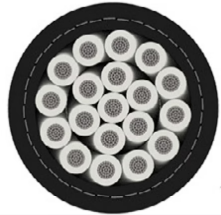
FPSO power cable

The maximum continuous ampacity for AmerCable 37-105319BS 8kV marine medium-voltage cable is 152 amperes when operating as a single conductor run in free air at the IEEE 45 standard reference conditions (45°C ambient temperature, 90°C conductor operating temperature). For multiple-conductor installations in cable trays typical of FPSO and offshore platform electrical systems, the ampacity derates to approximately 129 amperes due to reduced cooling efficiency when cables are bundled together. These ratings represent the maximum continuous current the cable can safely carry indefinitely without exceeding the 90°C maximum permissible conductor temperature specified by the cable's EPR (ethylene propylene rubber) insulation. The 152-ampere reference rating emerges from a careful balance between the cable's thermal conductivity, the copper conductor's heat-carrying capacity, the insulation's thermal stability, and the international standardization process that created IEEE 45 to ensure safe and consistent marine cable performance worldwide. The approximately 15% reduction from the single-conductor 152 amperes to the cable-tray 129 amperes reflects the real-world constraint that when multiple cables are installed side-by-side in ventilated tray systems, the outer surfaces of adjacent cables create a partial thermal barrier, reducing the ability of each individual cable to dissipate I²R losses to the surrounding environment. Understanding these two ampacity values and the conditions under which each applies is essential for safe electrical system design on ocean-going vessels and offshore platforms.

Maximum Continuous Ampacity: What is the current-carrying capacity for AmerCable 37-105319BS 8kV marine medium-voltage cable under IEEE 45 standards?

The maximum continuous ampacity for AmerCable 37-105319BS 8kV marine medium-voltage cable is 152 amperes when operating as a single conductor run in free air at the IEEE 45 standard reference conditions (45°C ambient temperature, 90°C conductor operating temperature). For multiple-conductor installations in cable trays typical of FPSO and offshore platform electrical systems, the ampacity derates to approximately 129 amperes due to reduced cooling efficiency when cables are bundled together. These ratings represent the maximum continuous current the cable can safely carry indefinitely without exceeding the 90°C maximum permissible conductor temperature specified by the cable’s EPR (ethylene propylene rubber) insulation. The 152-ampere reference rating emerges from a careful balance between the cable’s thermal conductivity, the copper conductor’s heat-carrying capacity, the insulation’s thermal stability, and the international standardization process that created IEEE 45 to ensure safe and consistent marine cable performance worldwide. The approximately 15% reduction from the single-conductor 152 amperes to the cable-tray 129 amperes reflects the real-world constraint that when multiple cables are installed side-by-side in ventilated tray systems, the outer surfaces of adjacent cables create a partial thermal barrier, reducing the ability of each individual cable to dissipate I²R losses to the surrounding environment. Understanding these two ampacity values and the conditions under which each applies is essential for safe electrical system design on ocean-going vessels and offshore platforms.
The act of splicing a medium-voltage cable in the field—joining two cable ends after they have already been installed in a drilling derrick or FPSO electrical room—occupies a unique and critical position in offshore electrical engineering. Unlike cable terminations (where the cable end is terminated to a switchgear cabinet or transformer winding terminal), field splices create a permanently joined section within the cable run itself. This joint must perform as if it were part of the original manufactured cable, maintaining perfect electrical, mechanical, and dielectric integrity in one of the world's most hostile environments: the vibration-laden, salt-spray-corroded, perpetually humid confines of an offshore platform. When a splice fails, it often fails catastrophically, potentially causing equipment damage, electrical hazards to personnel, and operational shutdowns that can cost hundreds of thousands of dollars per day.

Splicing Type MMV (37-105) 8kV Cables: Managing Tape and Braided Shields Offshore with Field-Proven Termination Techniques

The act of splicing a medium-voltage cable in the field—joining two cable ends after they have already been installed in a drilling derrick or FPSO electrical room—occupies a unique and critical position in offshore electrical engineering. Unlike cable terminations (where the cable end is terminated to a switchgear cabinet or transformer winding terminal), field splices create a permanently joined section within the cable run itself. This joint must perform as if it were part of the original manufactured cable, maintaining perfect electrical, mechanical, and dielectric integrity in one of the world’s most hostile environments: the vibration-laden, salt-spray-corroded, perpetually humid confines of an offshore platform. When a splice fails, it often fails catastrophically, potentially causing equipment damage, electrical hazards to personnel, and operational shutdowns that can cost hundreds of thousands of dollars per day.
When a marine electrical engineer opens a cable specification document for a 15 kV Type MMV cable, among the first technical parameters to be scrutinized is the notation of insulation level: either 100% or 133%. To the uninitiated, these seemingly abstract percentages might appear to be arbitrary marketing designations. In reality, they represent a profound engineering distinction rooted in power system grounding philosophy and the way electrical stress distributes across the cable insulation during both normal operation and fault conditions. Understanding this distinction is essential for anyone responsible for specifying cables for offshore platforms, FPSOs, or dynamic positioning vessels, because choosing the wrong insulation level can result in premature cable failures, cascading electrical faults, and operational disasters.

Understanding 100% vs. 133% Insulation Levels in Type MMV 15kV Marine Cables

When a marine electrical engineer opens a cable specification document for a 15 kV Type MMV cable, among the first technical parameters to be scrutinized is the notation of insulation level: either 100% or 133%. To the uninitiated, these seemingly abstract percentages might appear to be arbitrary marketing designations. In reality, they represent a profound engineering distinction rooted in power system grounding philosophy and the way electrical stress distributes across the cable insulation during both normal operation and fault conditions. Understanding this distinction is essential for anyone responsible for specifying cables for offshore platforms, FPSOs, or dynamic positioning vessels, because choosing the wrong insulation level can result in premature cable failures, cascading electrical faults, and operational disasters.
IEC 60092-354 mandates LSZH materials—typically halogen-free compounds based on thermoplastic polyethylene (HTPE), ethylene vinyl acetate (EVA), or polyurethane (PU). These materials meet stringent EN 61034 smoke emission criteria: less than 50% optical density when tested in a closed chamber, and minimal evolution of corrosive gases (measured as hydrochloric acid equivalent per EN 50267-2-1). For additional mechanical protection, ship cables are almost always specified with armoring: a steel wire or steel tape wrapping applied over the jacket.

IEC 60092 MV Cables vs. IEEE 1580 Type MMV: A Specifier’s Guide for Shipboard Power Distribution

IEC 60092-354 mandates LSZH materials—typically halogen-free compounds based on thermoplastic polyethylene (HTPE), ethylene vinyl acetate (EVA), or polyurethane (PU). These materials meet stringent EN 61034 smoke emission criteria: less than 50% optical density when tested in a closed chamber, and minimal evolution of corrosive gases (measured as hydrochloric acid equivalent per EN 50267-2-1). For additional mechanical protection, ship cables are almost always specified with armoring: a steel wire or steel tape wrapping applied over the jacket.
British Standard BS6883 covers the specifications for elastomer insulated cables for fixed wiring in ships (shipwiring) and on mobile and fixed offshore marine units. This standard specifies the requirements and test methods for shipboard fixed wiring of lighting, power, control, instrumentation and propulsion circuits with a voltage rating of up to 8.7/15kV.

What is BS6883 Cable?

BS6883電纜, BS6883船用電纜, 船用電纜, 海上電纜, 船用佈線電纜, 船舶電纜, LSZH電纜, LSHF電纜, 低煙無鹵電纜, EPR船用電纜, 海上電力電纜, 船用電纜, 657TQ電纜, 658TQ電纜, SW4型電纜, SW3型電纜, SW2型電纜, 鎧裝船用電纜, 非鎧裝船用電纜, 鋼絲編織電纜, HOFR電纜, 無鹵電纜, 阻燃船用電纜, 勞氏船級社電纜, DNV電纜, UKOOA電纜, 600/1000V船用電纜, 船用儀表電纜, 海上平台電纜, 鑽井平台電纜, 石油平台電纜, FPSO電纜, 耐火電纜, BS7917電纜, 彈性體絕緣電纜, EPR絕緣電纜, 鍍錫銅船用電纜,BS6883, BS6883 cable, marine cable, offshore cable, shipwiring cable, ship cable, LSZH cable, LSHF cable, low smoke halogen free cable, EPR marine cable, offshore power cable, shipboard cable, 657TQ cable, 658TQ cable, Type SW4 cable, Type SW3 cable, Type SW2 cable, armoured marine cable, unarmoured marine cable, GSWB cable, steel wire braid cable, HOFR cable, halogen free cable, flame retardant marine cable