
Longwall Shearer Power & Signal Transmission | Feichun Special Cables – Heavy-duty SHD-PCG round portable power cable 2kV with integrated control conductors for longwall shearer operations. Combined power and signal transmission, EPR insulation, metallic shielding, ICEA S-75-381 compliant. Technical specifications 3×1/0 to 3×4/0 AWG, ampacity 211-321A for underground coal mining equipment.
SHD-PCG Type Three-Conductor Round Portable Power Cable 2kV with Integrated Control Conductors
Advanced Combined Power and Signal Transmission Solution for Longwall Shearer Operations
Operational Context and Industrial Applications
The SHD-PCG cable series represents an advanced evolution in portable mining power cable engineering, specifically architected to address the complex requirements of longwall shearer operations where simultaneous power transmission and control signal communication prove essential for automated coal extraction systems. Unlike conventional mining cables that necessitate separate power and control cable installations, this integrated design consolidates both functions within a unified cylindrical cable assembly.
Longwall mining methodology utilizes mechanized shearing equipment that traverses horizontally across coal seams while simultaneously transmitting extracted material onto conveyor systems. These shearers demand continuous electrical power for cutting drum motors while simultaneously requiring reliable control signal pathways for automated positioning, cutting depth regulation, and operational parameter monitoring. The integrated architecture of SHD-PCG cables eliminates the complexity and installation burden associated with deploying parallel cable systems in confined underground environments.
Beyond longwall shearer applications, this cable configuration serves bulk material handling installations including bucket wheel excavators at surface mining sites, bridge reclaimers in stockyard facilities, barrel reclaiming machinery for aggregate recovery, and tripper conveyor systems requiring combined power distribution and positioning control. The round geometry provides omnidirectional flexibility advantageous for cable reeling systems and festoon installations where cable orientation varies during equipment travel movements.
Industry Compliance and Regulatory Certification Standards
- ICEA S-75-381 / NEMA WC 58: Insulated Cable Engineers Association and National Electrical Manufacturers Association Joint Standard addressing specifications for mining power cables with voltage ratings through 2kV
- ASTM B 172: American Society for Testing and Materials specification governing rope-lay-stranded copper conductors incorporating bunch-stranded or concentric-stranded member construction
- ASTM B 33: Standard specification establishing requirements for tinned soft or annealed copper wire manufactured for electrical applications requiring corrosion protection
- CAN/CSA C22.2 No. 96: Canadian Standards Association certification for portable power cables deployed in mining and heavy industrial environments
Detailed Construction Engineering and Material Composition
Power Conductor Design
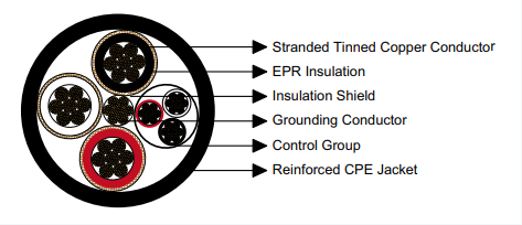
Primary power conductors utilize rope-lay stranded annealed copper with comprehensive tin plating applied to individual wire strands. This construction methodology delivers exceptional mechanical flexibility essential for reeling applications while the tin coating prevents copper oxidation in humid underground atmospheres and facilitates reliable electrical terminations.
Dielectric Insulation Layer
Ethylene Propylene Rubber (EPR) compound serves as the primary dielectric insulation material. EPR exhibits superior electrical properties across wide temperature ranges, exceptional resistance to tracking and corona discharge, outstanding flexibility at low temperatures, and comprehensive immunity to moisture ingress and chemical contamination.
Electromagnetic Shielding System
Each power conductor incorporates an independent metallic shield constructed from tinned copper wire interwoven with textile reinforcement fibers. This braid shield configuration provides electrostatic screening, reduces electromagnetic interference affecting sensitive control circuits, and contributes mechanical reinforcement protecting the underlying insulation from abrasion damage.
Control Conductor Assembly
Three dedicated control conductors manufactured from tinned copper stranding with individual EPR insulation layers are color-coded black, white, and red for circuit identification. These conductors are encapsulated within a thermosetting elastomeric jacket forming an integrated control group suitable for transmitting positioning signals, operational commands, and sensor feedback data.
Central Grounding Conductor
A tinned copper grounding conductor positioned at the geometric center of the cable assembly provides the primary equipment grounding pathway. This central location ensures balanced mechanical properties and maintains consistent grounding conductor integrity regardless of cable bending orientation during service.
Protective Outer Jacket
The outermost protective layer consists of reinforced extra-heavy-duty Chlorinated Polyethylene (CPE) formulated in black pigmentation. CPE jacketing delivers exceptional abrasion resistance against mineral particles, comprehensive flame propagation resistance meeting mining safety codes, resistance to oil and hydrocarbon exposure, and maintained flexibility across ambient temperature extremes.
Alternative Jacketing Material Options
While standard production employs CPE jacketing material, alternative elastomeric compounds can be specified to address unique environmental conditions. Chlorosulfonated Polyethylene (CSP) provides enhanced resistance to aggressive chemical exposure and elevated temperature service. Polychloroprene (PCP) delivers improved low-temperature flexibility beneficial in surface mining applications experiencing freezing conditions. Nitrile Butadiene Rubber (NBR) offers superior resistance to petroleum-based fluids and hydraulic oils encountered near mobile equipment. Polyvinyl Chloride (PVC) represents a cost-effective alternative for applications with reduced mechanical stress and controlled environmental conditions.
For installations demanding maximum puncture resistance and mechanical durability, a dual-layer jacket construction incorporating textile reinforcement fibers between inner and outer elastomeric layers can be engineered. This configuration substantially increases the cable’s resistance to sharp object penetration and crushing forces in extreme-duty mining environments.
Performance Specifications: Thermal and Mechanical Parameters
The 90-degree Celsius continuous conductor operating temperature establishes the thermal boundary for sustained current-carrying capability. EPR insulation maintains dielectric integrity throughout this temperature range while providing thermal margin preventing premature aging. Operating conductors below this maximum temperature through proper ampacity derating extends service life significantly.
The minimum bending radius specification, calculated as six times the overall cable diameter, represents the tightest curvature permissible during installation and service without inducing mechanical damage to conductor stranding, insulation compression, or shield integrity. Cable routing and reel diameter specifications must accommodate this minimum radius to prevent performance degradation.
Complete Technical Specifications and Dimensional Data
| Construction Size (Cores × AWG/kcmil) | Conductor Stranding | Ground Conductor (AWG/kcmil) | Control Conductors (AWG/kcmil) | Insulation Wall (inch / mm) | Jacket Thickness (inch / mm) | Overall Diameter (inch / mm) | Mass per Length (lbs/kft / kg/km) | Current Rating (Amperes) |
|---|---|---|---|---|---|---|---|---|
| 3 × 1/0 AWG | 259 strands | 3 AWG | 8 AWG (×3) | 0.08 / 2.0 | 0.205 / 5.2 | 2.05 / 52.1 | 3092 / 4602 | 211 |
| 3 × 2/0 AWG | 329 strands | 2 AWG | 8 AWG (×3) | 0.08 / 2.0 | 0.220 / 5.6 | 2.25 / 57.1 | 3698 / 5503 | 243 |
| 3 × 3/0 AWG | 413 strands | 1 AWG | 8 AWG (×3) | 0.08 / 2.0 | 0.220 / 5.6 | 2.32 / 58.9 | 4295 / 6392 | 279 |
| 3 × 4/0 AWG | 532 strands | 1/0 AWG | 8 AWG (×3) | 0.08 / 2.0 | 0.250 / 6.3 | 2.62 / 66.5 | 5115 / 7612 | 321 |
Ampacity Calculation Foundation: Current-carrying capacity values represent calculations based upon 90°C maximum conductor operating temperature with 40°C ambient air temperature environment, utilizing calculation methodologies prescribed in ICEA S-75-381 standard documentation. Field ampacity may differ based upon cable grouping configurations, ventilation characteristics, thermal soil properties, and cyclic loading patterns specific to individual installations.
Comparative Analysis: Model Selection and Performance Characteristics
Engineering Considerations for Conductor Size Specification
Selecting the appropriate conductor cross-sectional area for a longwall shearer or material handling installation requires comprehensive evaluation of electrical performance requirements balanced against mechanical handling constraints and economic considerations. Each conductor size increment delivers increased current-carrying capacity enabling higher power transmission, but simultaneously increases cable weight, stiffness, and material costs.
3 × 1/0 AWG Configuration
- Ampacity: 211A (baseline reference)
- Conductor area: 53.5 mm² per phase
- Cable mass: 4602 kg/km (lightest option)
- Diameter: 52.1 mm (most compact)
- Optimal for: Moderate-duty longwall shearers, auxiliary mining equipment, installations with cable length constraints under 100 meters where voltage drop remains acceptable
- Economic advantage: Lower material cost and reduced reel infrastructure requirements
3 × 2/0 AWG Configuration
- Ampacity: 243A (+15% versus 1/0)
- Conductor area: 67.4 mm² per phase
- Cable mass: 5503 kg/km (+20%)
- Diameter: 57.1 mm
- Optimal for: Standard longwall shearer installations, medium-capacity bucket wheel reclaimers, applications requiring power transmission up to 150 meters with acceptable resistive losses
- Balanced performance: Industry-standard specification providing reliable operation without excessive weight penalty
3 × 3/0 AWG Configuration
- Ampacity: 279A (+32% versus 1/0)
- Conductor area: 85.0 mm² per phase
- Cable mass: 6392 kg/km (+39%)
- Diameter: 58.9 mm
- Optimal for: High-capacity longwall systems, extended cable runs 150-250 meters requiring voltage drop compensation, heavy-duty tripper conveyors with frequent starting cycles
- Performance advantage: Superior thermal margin accommodates overload conditions and elevated ambient temperatures in deep underground operations
3 × 4/0 AWG Configuration
- Ampacity: 321A (+52% versus 1/0)
- Conductor area: 107.2 mm² per phase (largest)
- Cable mass: 7612 kg/km (heaviest)
- Diameter: 66.5 mm (maximum diameter)
- Optimal for: Maximum-capacity longwall shearers with high-horsepower cutting motors, primary power distribution for large-scale bulk handling systems, installations exceeding 250 meters requiring minimal voltage drop
- Premium capability: Highest current rating accommodates future equipment upgrades and sustained heavy-load operation without thermal stress
Integrated Control Conductor Functionality and Applications
The incorporation of three independent control conductors within the primary power cable assembly enables sophisticated automation and monitoring capabilities essential for modern longwall mining operations. These 8 AWG control circuits transmit positioning encoder signals from shearer travel motors, communicate cutting depth sensor data to surface control systems, relay hydraulic pressure monitoring information, and distribute control commands for automated shearer operation sequences.
In bulk material handling applications utilizing this cable on bridge reclaimers, bucket wheel excavators, or barrel reclaiming machinery, the control conductors facilitate integration with programmable logic controller (PLC) systems governing automated positioning, load monitoring, and operational sequencing. The color-coded insulation (black, white, red) simplifies field termination and troubleshooting during installation and maintenance activities.
The central positioning of the grounding conductor provides consistent equipment grounding regardless of cable twisting or bending during reeling operations, maintaining personnel safety and ensuring reliable ground fault protection circuit operation throughout the cable service life.
Dr. Robert Hutchinson, P.E., Ph.D.
Throughout twenty-two years of specialized focus on underground coal mining electrical infrastructure, I have engineered, commissioned, and optimized power distribution systems for longwall mining operations across three continents. My professional experience encompasses direct involvement with electrical system design for operations producing over 15 million tons of coal annually through longwall extraction methodologies.
My career trajectory includes eight years as Electrical Engineering Manager for Consolidated Mining Group directing electrical infrastructure for four operating longwall mines, seven years with Alpine Equipment Corporation as Senior Design Engineer responsible for longwall shearer electrical systems and portable power cable specifications, and five years with International Heavy Machinery Ltd. developing cable reeling systems and power distribution equipment for surface mining operations.
This technical documentation reflects accumulated knowledge from field experience specifying, testing, and evaluating portable power cable performance in longwall mining environments where equipment operates continuously under 600 meters of overburden in coal seams averaging 2.4 meters in height. I have personally investigated cable failure mechanisms, optimized cable selection for specific geological conditions, and developed installation practices minimizing premature cable degradation in abrasive underground environments.
My doctoral research at Colorado Mining Institute focused on electrical system reliability in mechanized underground mining, with specific emphasis on portable cable degradation mechanisms and predictive maintenance methodologies. This academic foundation combined with extensive field experience provides comprehensive understanding of the engineering principles governing portable mining cable performance and longevity.
- Professional Engineer (P.E.) License – Electrical Engineering, State Board of Professional Engineers
- Doctor of Philosophy (Ph.D.) – Mining Engineering, Colorado Mining Institute (2009)
- Master of Science (M.S.) – Electrical Power Systems, Technical University (2003)
- Bachelor of Science (B.S.) – Electrical Engineering Technology, State Polytechnic University (2000)
- Certified Mine Electrical Systems Engineer – Mine Safety and Health Administration (MSHA)
- Underground Mine Foreman Certification – Department of Mining Safety
- Senior Member, Institute of Electrical and Electronics Engineers (IEEE)
- Professional Member, Society for Mining, Metallurgy and Exploration (SME)
- Technical Committee Member, ICEA Cable Standards Development
- Published Author: “Portable Cable Performance in Longwall Mining Applications” – Mining Engineering Journal (2018)


