
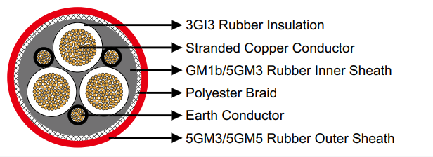
(N)TSCGEWOEU MV Cable
Medium Voltage Reeling Systems for Heavy Mobile Equipment
High Voltage Technical Support:
Anhui Feichun Special Cable Co., Ltd.
Heavy-Duty Medium Voltage Reeling Cable Technology
The (N)TSCGEWOEU medium voltage reeling cable represents the pinnacle of engineering excellence in mobile heavy equipment power distribution. Specifically engineered for extreme mechanical stress environments, this cable delivers reliable electrical transmission for excavators, spreaders, loading bridges, gantry cranes, and construction machinery operating in hazardous explosive atmospheres and demanding industrial conditions.
🏗️ Heavy Equipment Applications
- Large excavators and draglines for open-pit mining operations
- Bucket wheel spreaders and material handling systems
- Loading bridges and ship-to-shore crane installations
- Container gantry cranes in port terminal operations
- Mobile construction machinery requiring continuous power
- Demolition and material processing equipment
⚡ Advanced Engineering Features
- VDE 0250 Part 813 certification for mobile equipment
- Multi-voltage capability: 3.6/6kV through 18/30kV systems
- Semiconductive screening layers for field stress control
- Polyester anti-torsion braid reinforcement technology
- Explosion-proof rating for hazardous environments
- Enhanced EPR type 3GI3 insulation system
International Medium Voltage Standards & Compliance Matrix
Medium voltage reeling cables must comply with stringent international standards to ensure safety and reliability in mobile heavy equipment applications. Understanding regional equivalencies is critical for global operations and regulatory compliance.
🇩🇪 German VDE Standard
Primary designation under VDE 0250-813 for medium voltage mobile applications
🇪🇺 European Harmonized
European standard for medium voltage power cables with enhanced screening
🇬🇧 British Standard
UK medium voltage cables for mobile and portable equipment
🇺🇸 American Standard
US standard for medium voltage portable power cables
🇦🇺 Australian Standard
Australian standard for medium voltage mining cables
🇨🇳 Chinese National
Chinese standards for medium voltage mining equipment cables
Advanced Multi-Layer Construction & Materials Engineering
⚠️ High Voltage Safety Notice
Medium voltage cables require specialized installation, testing, and maintenance procedures. Only qualified electrical personnel certified for medium voltage systems should handle these cables. Proper grounding, insulation testing, and arc flash protection are mandatory.
Conductor & Screening System
Conductor: Class 5 flexible stranded copper (DIN VDE 0295)
Inner Semiconductive Layer: Extruded field-grading compound
Outer Semiconductive Layer: Strippable screening material
Purpose: Uniform electric field distribution and stress relief
Insulation Technology
Material: EPR type 3GI3 ethylene propylene rubber
Properties: Superior dielectric strength and thermal stability
Temperature Rating: Continuous 90°C, emergency 130°C
Advantage: Excellent flexibility and ozone resistance
Mechanical Protection System
Inner Sheath: Rubber type GM1b/5GM3 compound
Reinforcement: Polyester anti-torsion braid protection
Outer Sheath: Chlorinated rubber 5GM3/5GM5
Features: Flame retardant, oil resistant, explosion-proof
Comprehensive Voltage Class Specifications
3.6/6kV System Configuration Matrix
| Main Cores × Cross Section | Earth Cores × Cross Section | Minimum Overall Diameter | Maximum Overall Diameter | Nominal Weight | Current Rating (A) |
|---|---|---|---|---|---|
| 3×25 mm² | 3×25/3 mm² | 39.0 mm | 42.0 mm | 2410 kg/km | 105 |
| 3×35 mm² | 3×25/3 mm² | 42.0 mm | 45.0 mm | 2995 kg/km | 135 |
| 3×50 mm² | 3×25/3 mm² | 45.0 mm | 48.0 mm | 3645 kg/km | 170 |
| 3×70 mm² | 3×35/3 mm² | 50.0 mm | 54.0 mm | 4760 kg/km | 220 |
| 3×95 mm² | 3×50/3 mm² | 54.0 mm | 58.0 mm | 5580 kg/km | 270 |
| 3×120 mm² | 3×70/3 mm² | 58.0 mm | 62.0 mm | 6690 kg/km | 310 |
| 3×150 mm² | 3×70/3 mm² | 63.0 mm | 67.0 mm | 7990 kg/km | 360 |
| 3×185 mm² | 3×95/3 mm² | 67.0 mm | 72.0 mm | 9330 kg/km | 420 |
6/10kV System Configuration Matrix
| Main Cores × Cross Section | Earth Cores × Cross Section | Minimum Overall Diameter | Maximum Overall Diameter | Nominal Weight | Current Rating (A) |
|---|---|---|---|---|---|
| 3×25 mm² | 3×25/3 mm² | 40.0 mm | 43.0 mm | 2450 kg/km | 100 |
| 3×35 mm² | 3×25/3 mm² | 43.0 mm | 46.0 mm | 3035 kg/km | 130 |
| 3×50 mm² | 3×25/3 mm² | 46.0 mm | 49.0 mm | 3690 kg/km | 165 |
| 3×70 mm² | 3×35/3 mm² | 51.0 mm | 55.0 mm | 4800 kg/km | 215 |
| 3×95 mm² | 3×50/3 mm² | 55.0 mm | 59.0 mm | 5620 kg/km | 260 |
| 3×120 mm² | 3×70/3 mm² | 59.0 mm | 63.0 mm | 6740 kg/km | 300 |
| 3×150 mm² | 3×70/3 mm² | 64.0 mm | 68.0 mm | 8040 kg/km | 350 |
| 3×185 mm² | 3×95/3 mm² | 69.0 mm | 74.0 mm | 9380 kg/km | 405 |
8.7/15kV System Configuration Matrix
| Main Cores × Cross Section | Earth Cores × Cross Section | Minimum Overall Diameter | Maximum Overall Diameter | Nominal Weight | Current Rating (A) |
|---|---|---|---|---|---|
| 3×25 mm² | 3×25/3 mm² | 42.1 mm | 45.1 mm | 2707 kg/km | 95 |
| 3×35 mm² | 3×25/3 mm² | 44.9 mm | 47.9 mm | 3198 kg/km | 125 |
| 3×50 mm² | 3×25/3 mm² | 49.5 mm | 53.5 mm | 4083 kg/km | 160 |
| 3×70 mm² | 3×35/3 mm² | 53.1 mm | 57.1 mm | 5028 kg/km | 205 |
| 3×95 mm² | 3×50/3 mm² | 57.3 mm | 61.3 mm | 6216 kg/km | 250 |
| 3×120 mm² | 3×70/3 mm² | 63.0 mm | 67.0 mm | 7673 kg/km | 290 |
| 3×150 mm² | 3×70/3 mm² | 66.6 mm | 70.6 mm | 8852 kg/km | 335 |
| 3×185 mm² | 3×95/3 mm² | 70.5 mm | 74.5 mm | 10351 kg/km | 390 |
| 3×240 mm² | 3×120/3 mm² | 78.0 mm | 82.0 mm | 13125 kg/km | 470 |
| 3×300 mm² | 3×150/3 mm² | 84.9 mm | 89.9 mm | 16020 kg/km | 540 |
12/20kV System Configuration Matrix
| Main Cores × Cross Section | Earth Cores × Cross Section | Minimum Overall Diameter | Maximum Overall Diameter | Nominal Weight | Current Rating (A) |
|---|---|---|---|---|---|
| 3×25 mm² | 3×25/3 mm² | 46.0 mm | 49.0 mm | 3050 kg/km | 90 |
| 3×35 mm² | 3×25/3 mm² | 49.0 mm | 52.0 mm | 3490 kg/km | 120 |
| 3×50 mm² | 3×25/3 mm² | 53.0 mm | 57.0 mm | 4340 kg/km | 150 |
| 3×70 mm² | 3×35/3 mm² | 57.0 mm | 61.0 mm | 5320 kg/km | 195 |
| 3×95 mm² | 3×50/3 mm² | 61.0 mm | 65.0 mm | 6360 kg/km | 240 |
| 3×120 mm² | 3×70/3 mm² | 67.0 mm | 71.0 mm | 7810 kg/km | 280 |
| 3×150 mm² | 3×70/3 mm² | 70.0 mm | 74.0 mm | 8900 kg/km | 320 |
| 3×185 mm² | 3×95/3 mm² | 76.0 mm | 80.0 mm | 10700 kg/km | 375 |
14/25kV System Configuration Matrix
High voltage class for heavy-duty crane and excavator applications requiring maximum power transmission capability.
18/30kV System Configuration Matrix
Ultra-high voltage class for the largest mobile equipment and specialized industrial applications.
Technical FAQ & Expert Guidance
What are the critical considerations for medium voltage reeling cable selection?
Medium voltage reeling cable selection requires careful analysis of multiple factors: operating voltage class, current carrying requirements, mechanical stress levels, environmental conditions, and reeling system specifications. The semiconductive screening layers are crucial for electric field control at voltages above 1kV. Anti-torsion reinforcement prevents conductor deformation during continuous reeling operations. Consider voltage regulation, short-circuit currents, and protection coordination when specifying cable size. Factor in ambient temperature, altitude, and proximity to heat sources for current rating adjustments.
How does the anti-torsion braid reinforcement enhance cable performance?
The polyester anti-torsion braid reinforcement is engineered to resist rotational forces and mechanical stresses inherent in reeling applications. This reinforcement prevents conductor bunching, insulation displacement, and screening damage during continuous winding/unwinding cycles. The braid maintains cable geometry under tension while providing radial strength against crushing forces. This technology significantly extends cable service life in mobile applications by maintaining electrical integrity and preventing premature failures caused by mechanical deformation.
What safety protocols are required for medium voltage cable installation?
Medium voltage cable installation demands strict safety protocols and qualified personnel certification. Key requirements include: comprehensive pre-installation testing (insulation resistance, continuity, phase rotation), proper earthing and bonding procedures, arc flash hazard analysis and appropriate PPE selection, voltage testing before and after termination, adherence to minimum bend radius specifications, and proper screen termination techniques. All installation work must comply with national electrical codes, manufacturer specifications, and company safety standards. Post-installation commissioning tests including high-potential testing and thermal imaging are mandatory.
How do semiconductive layers improve cable reliability in medium voltage applications?
Semiconductive layers are essential for electric field stress control in medium voltage cables. The inner semiconductive layer provides a smooth, uniform interface between conductor and insulation, eliminating air voids and sharp edges that could cause corona discharge. The outer semiconductive layer ensures uniform field distribution across the insulation surface. This design prevents partial discharge activity, reduces dielectric stress concentrations, and significantly improves cable longevity. Proper semiconductive layer design is critical for cables operating above 3.6kV to prevent insulation degradation and premature failure.
What maintenance practices maximize reeling cable service life?
Effective maintenance for reeling cables includes regular visual inspections for outer sheath damage, thermal imaging to identify hot spots, insulation resistance testing, and reeling system mechanical inspections. Monitor cable tension during operation to prevent overstressing. Implement proper storage practices when equipment is idle – avoid tight coiling and exposure to extreme temperatures. Conduct periodic partial discharge testing for early detection of insulation degradation. Maintain detailed records of installation, testing, and maintenance activities. Replace cables showing signs of mechanical damage, insulation deterioration, or recurring faults to prevent catastrophic failures.
Can these cables operate in explosive atmosphere classifications?
Yes, the (N)TSCGEWOEU cable is specifically designed for explosive atmosphere applications with appropriate hazardous area certifications. The flame-retardant outer sheath materials and construction meet requirements for Zone 1 and Zone 2 explosive gas atmospheres. However, complete system safety requires proper cable termination using certified explosion-proof enclosures, appropriate cable gland selection, and compliance with ATEX directives or IECEx standards. The cable installation must be part of a comprehensive hazardous area electrical design including equipment certification, earthing systems, and maintenance procedures specific to explosive environments.


