
HD 626 S1 Type 9F Cable Code Designation: Comprehensive Technical Guide
Anhui Feichun Special Cable Co., Ltd. (安徽飞纯特种电缆有限公司)
Professional Manufacturer of Overhead Distribution Cables and Special Application Cables
Introduction to HD 626 S1 Type 9F Cable
The HD 626 S1 Type 9F cable represents a sophisticated overhead distribution cable system designed for modern electrical infrastructure. This cable designation falls under the European harmonized standard HD 626 S1, which specifies comprehensive requirements for overhead distribution cables rated at 0.6/1 (1.2) kV used primarily in public power distribution systems. According to the harmonized document HD 626 S1:1996, these cables are engineered for overhead power distribution systems with maximum system voltage not exceeding 1.2 kV, providing reliable electrical transmission in both urban and rural electrification projects.
Key Application Scope: HD 626 S1 cables serve as the backbone of modern aerial bundled cable (ABC) systems, offering enhanced safety and reliability compared to traditional bare conductor systems while reducing power losses and improving system efficiency. These cables are extensively deployed in mobile machinery power systems and overhead distribution networks globally.
The Type 9F designation within the HD 626 S1 framework indicates a specific configuration featuring aluminum conductors with XLPE (cross-linked polyethylene) insulation in a bundled arrangement. This configuration has gained widespread acceptance in the electrical industry due to its superior performance characteristics, cost-effectiveness, and enhanced safety features. Research conducted by major cable manufacturers, including Feichun Special Cable, demonstrates that XLPE insulated cables exhibit significantly improved thermal performance and moisture resistance compared to conventional PVC insulated variants.
Understanding the HD 626 S1 Type 9F Code Designation
The cable designation system employed in HD 626 S1 follows a systematic nomenclature that provides comprehensive information about the cable’s construction, materials, and intended application. Each element in the code designation conveys specific technical information critical for proper cable selection and installation.
Code Structure Breakdown:
This designation system aligns with international harmonization standards developed by CENELEC (European Committee for Electrotechnical Standardization), ensuring interoperability and consistent performance specifications across European markets. The systematic approach to cable designation facilitates accurate specification, procurement, and installation procedures while minimizing the risk of material selection errors.
Purpose and Primary Applications
Electrical Distribution Infrastructure
HD 626 S1 Type 9F cables serve as critical components in modern overhead distribution networks. The primary purpose of these cables encompasses power transmission from distribution transformers to end-user service points, replacing traditional bare conductor systems with insulated alternatives that offer superior safety and reliability characteristics. Industry data from the International Electrotechnical Commission indicates that aerial bundled cable systems reduce electrical accidents by approximately 80% compared to bare conductor installations, while simultaneously decreasing power theft and improving system reliability.
Rural Electrification Projects
These cables demonstrate particular effectiveness in rural electrification initiatives where cost constraints and installation complexity present significant challenges. The bundled configuration simplifies installation procedures, reduces right-of-way requirements, and minimizes environmental impact. Comparative studies conducted by mining infrastructure specialists reveal that ABC systems require approximately 40% less corridor width compared to conventional bare conductor installations, making them ideal for densely vegetated or constrained installation environments.
Urban and Suburban Distribution
In urban settings, HD 626 S1 cables provide aesthetic advantages while maintaining electrical performance. The insulated, bundled configuration reduces visual impact and enables installation in locations where bare conductors would be impractical or hazardous. Applications in industrial crane systems and material handling equipment further demonstrate the versatility of these cable configurations.
Technical Characteristics and Performance Parameters
Electrical Properties
The electrical performance of HD 626 S1 Type 9F cables derives from the sophisticated interplay between conductor design, insulation materials, and geometric configuration. XLPE insulation provides exceptional dielectric strength, exhibiting test voltage capabilities of 3.5 kV for rated voltages of 0.6/1 kV, ensuring robust performance under both normal operating conditions and transient overvoltage scenarios.
| Parameter | Specification | Test Standard | Performance Benefit |
|---|---|---|---|
| Rated Voltage U₀/U (Um) | 0.6/1 (1.2) kV | HD 626 S1:1996 | Standard distribution voltage compatibility |
| Test Voltage | 3.5 kV AC (5 min) | EN 60811-1-3 | Insulation integrity verification |
| Maximum Conductor Temperature | 90°C continuous | HD 605 S1 | Enhanced current carrying capacity |
| Short Circuit Temperature | 250°C (max 5 seconds) | IEC 60949 | Fault current withstand capability |
| Minimum Installation Temperature | -5°C | HD 626 S1 | Cold weather installation flexibility |
| Minimum Service Temperature | -40°C | HD 605 S1 | Arctic climate compatibility |
Mechanical Properties
The mechanical characteristics of Type 9F cables reflect advanced engineering optimized for overhead installation environments. Stranded aluminum conductors provide enhanced flexibility while maintaining adequate tensile strength for aerial applications. Industry testing data indicates that properly installed ABC systems demonstrate superior wind load performance compared to bare conductor configurations, with reduced galloping and aeolian vibration phenomena.
Flexibility Performance: Stranded construction enables bending radius of 10 times the cable outer diameter during installation and 20 times diameter during operation, facilitating installation around corners and obstacles while minimizing mechanical stress on conductors and insulation systems.
Environmental Resistance
XLPE insulation demonstrates exceptional resistance to environmental stressors including moisture, ultraviolet radiation, and chemical contamination. Accelerated aging studies conducted according to IEC 60216 standards indicate projected service life exceeding 40 years under normal operating conditions. This superior environmental resistance makes HD 626 S1 cables particularly suitable for installation in coastal regions, industrial areas, and locations with elevated pollution levels. Research from mining cable specialists in Chile confirms the robust performance of XLPE insulated cables in harsh mining and industrial environments.
| Environmental Factor | Resistance Level | Performance Standard |
|---|---|---|
| UV Radiation | Excellent (>2000 hours) | EN 60811-2-1 |
| Water Immersion | Continuous | IEC 60502-1 |
| Ozone Resistance | No cracking at 200 pphm | IEC 60811-2-1 |
| Chemical Resistance | Acids, alkalis, oils | EN 60811-404 |
| Flame Performance | Self-extinguishing | IEC 60332-1-2 |
Material Structure and Construction Details
Conductor System
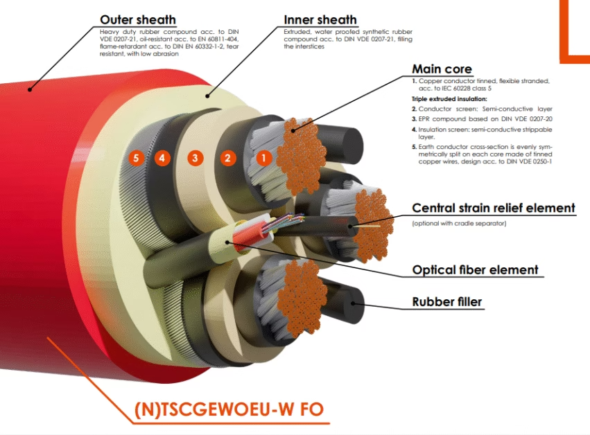
The conductor system in HD 626 S1 Type 9F cables utilizes high-purity aluminum conforming to EN 50182 specifications. Aluminum alloy 1350-H19 (minimum 99.5% purity) provides the optimal balance between electrical conductivity, mechanical strength, and weight considerations. The stranded configuration typically employs Class 2 compacted stranding according to IEC 60228, offering enhanced current carrying capacity through improved conductor fill factor while maintaining necessary flexibility for overhead installation.
Conductor Specifications: Available cross-sections range from 16 mm² to 240 mm², with conductor resistance values at 20°C not exceeding values specified in IEC 60228. Typical configurations include 25 mm², 35 mm², 50 mm², 70 mm², 95 mm², 120 mm², and 150 mm² for phase conductors, with neutral conductors sized according to load current and fault protection requirements.
Insulation System
XLPE insulation represents the technological heart of Type 9F cable performance. The cross-linking process transforms thermoplastic polyethylene into a thermoset material exhibiting superior thermal, mechanical, and electrical properties. Manufacturing processes employ peroxide-initiated cross-linking under controlled temperature and pressure conditions, achieving cross-linking degrees exceeding 70% as verified by gel content testing per ASTM D2765. This molecular transformation results in significantly enhanced high-temperature performance, with continuous operating temperature ratings of 90°C compared to 70°C for conventional PVC insulated cables.
| Conductor Size (mm²) | Insulation Thickness (mm) | Nominal Diameter (mm) | Approx. Weight (kg/km) |
|---|---|---|---|
| 16 | 1.0 | 6.8 | 95 |
| 25 | 1.0 | 7.6 | 125 |
| 35 | 1.0 | 8.5 | 165 |
| 50 | 1.0 | 9.5 | 215 |
| 70 | 1.4 | 11.6 | 310 |
| 95 | 1.4 | 13.2 | 405 |
| 120 | 1.4 | 14.6 | 495 |
| 150 | 1.8 | 17.2 | 655 |
Cable Assembly Configuration
Type 9F cables typically employ a bundled configuration where insulated phase conductors are helically laid around a central neutral or messenger conductor. This geometric arrangement provides mechanical support while maintaining compact cross-sectional dimensions. The neutral conductor may consist of bare aluminum alloy (AAAC), aluminum with steel core (ACSR), or insulated aluminum, depending on specific installation requirements and local electrical codes. The helical lay length typically ranges from 10 to 20 times the cable diameter, optimizing mechanical flexibility while maintaining geometric stability during installation and operation.
Standards Compliance and Regulatory Framework
Primary Standards
HD 626 S1 Type 9F cables must demonstrate compliance with a comprehensive framework of international and regional standards ensuring electrical safety, mechanical reliability, and consistent manufacturing quality. The foundation standard, HD 626 S1:1996 (including Amendment A1:1997), establishes fundamental requirements for overhead distribution cables rated 0.6/1 (1.2) kV. This harmonized document has been implemented in national standards across European member states, facilitating international trade and ensuring consistent performance expectations.
According to GlobalSpec Standards Database: “HD 626 applies to cables of rated voltage U₀/U(Um) = 0.6/1(1.2) kV used in overhead power distribution systems mainly for public distribution, of maximum system voltage not exceeding 1.2 kV. Test methods are specified in HD 383, HD 405, EN 60811 and in HD 605 or in Part 2 of this HD.”
Testing Standards and Protocols
Comprehensive testing protocols verify compliance with specified performance parameters throughout the manufacturing process and product lifecycle. Type testing establishes fundamental product capabilities, while routine testing ensures consistent manufacturing quality across all production batches. Sample testing provides ongoing quality assurance through periodic verification of critical parameters.
| Test Category | Standard Reference | Test Parameters | Acceptance Criteria |
|---|---|---|---|
| Conductor Resistance | IEC 60228 | DC resistance at 20°C | ≤ specified values per conductor class |
| Insulation Thickness | HD 605 S1 | Minimum thickness measurement | ≥ nominal – tolerance (typically 10%) |
| High Voltage Test | EN 60811-1-3 | 3.5 kV AC, 5 minutes | No breakdown or flashover |
| Mechanical Properties | EN 60811-1-1 | Tensile strength and elongation | Min 12.5 MPa, 150% elongation |
| Hot Set Test | EN 60811-2-1 | 200°C, 15 minutes load | Permanent deformation ≤ 50% |
| Ageing Resistance | EN 60811-1-2 | Thermal ageing at 135°C | Retention of 80% properties |
| Cold Bend Test | HD 605 S1 | -25°C flexibility test | No insulation cracks |
International Equivalents
Various national and regional standards provide equivalent specifications for overhead distribution cables, enabling global deployment while maintaining consistent performance expectations. BS 7870 serves as the British equivalent, while AS/NZS 3560.1 governs Australian and New Zealand applications. Understanding these equivalent standards facilitates international procurement and ensures compatibility across different regulatory jurisdictions.
Safety Thresholds and Operational Limits
Current Carrying Capacity
The ampacity of HD 626 S1 Type 9F cables depends on multiple factors including conductor cross-section, installation configuration, ambient temperature, and thermal environment. Published ampacity tables based on IEC 60287 calculations provide conservative ratings assuming specific reference conditions (30°C ambient temperature, 0.9 load factor, 1.0 m spacing). Field installations may achieve different performance based on actual environmental conditions and installation parameters.
| Conductor Size (mm²) | Current Rating (A) at 30°C | Current Rating (A) at 40°C | Max. Short Circuit Current (kA) for 1s |
|---|---|---|---|
| 16 | 70 | 63 | 1.0 |
| 25 | 95 | 86 | 1.6 |
| 35 | 120 | 108 | 2.2 |
| 50 | 150 | 135 | 3.1 |
| 70 | 195 | 175 | 4.4 |
| 95 | 240 | 216 | 5.9 |
| 120 | 280 | 252 | 7.5 |
| 150 | 325 | 293 | 9.4 |
⚠️ Critical Safety Parameters
Temperature Limits:
- Maximum continuous conductor temperature: 90°C
- Emergency overload temperature (100 hours/year): 105°C
- Short circuit temperature (maximum 5 seconds): 250°C
- Minimum installation temperature: -5°C (special precautions required below 0°C)
- Minimum service temperature: -40°C
Voltage Stress Limits:
- Maximum continuous operating voltage: 1.0 kV phase-to-neutral
- Maximum system voltage: 1.2 kV
- Lightning impulse withstand: 20 kV (1.2/50 μs)
- Power frequency withstand: 3.5 kV AC for 5 minutes
Mechanical Stress Limits:
- Minimum bending radius during installation: 10 × cable diameter
- Minimum bending radius during service: 20 × cable diameter
- Maximum tensile load during installation: 50 N/mm² of conductor cross-section
- Maximum span length: Calculated per IEC 60826 considering sag, tension, and wind loading
Protection Requirements
Proper protection systems ensure safe operation within specified parameters while preventing damage to cable systems and connected equipment. Overcurrent protection must coordinate with cable thermal characteristics, providing disconnection before conductor temperatures exceed safe limits. Ground fault protection becomes particularly critical in aerial distribution systems, where phase-to-earth faults pose significant safety hazards. International standards recommend maximum disconnection times of 0.4 seconds for final distribution circuits rated above 32 amperes.
Installation Precautions and Best Practices
Pre-Installation Considerations
Successful cable installation requires thorough planning and consideration of environmental factors, mechanical constraints, and electrical requirements. Site surveys should evaluate pole placement, span lengths, terrain characteristics, and potential obstacles. Mechanical calculations must verify that selected conductor sizes and installation tensions remain within safe limits under worst-case loading scenarios including maximum ice loading and wind pressure. The experience from industrial reeling cable applications demonstrates the importance of proper mechanical design in ensuring long-term cable system reliability.
Installation Procedures
Proper installation techniques prove critical for achieving design performance and service life expectations. Cable handling during installation must avoid excessive bending, twisting, or tension that could damage conductors or insulation. Unreeling should occur from rotating reels rather than stationary reels to prevent torsional stress. Installation should not proceed when ambient temperatures fall below -5°C unless special precautions including pre-warming are implemented.
Installation Best Practices:
Cable Handling:
- Store cable reels on level surfaces, avoiding prolonged exposure to direct sunlight
- Inspect cable upon delivery for mechanical damage or moisture ingress
- Maintain minimum bending radius of 10 times cable diameter during unreeling
- Use appropriate pulling equipment designed for overhead cable installation
- Apply pulling tension gradually, avoiding shock loading
Mechanical Installation:
- Calculate sag and tension values based on conductor characteristics and span length
- Ensure adequate ground clearance per local electrical codes (typically minimum 4.0 meters for distribution circuits)
- Install appropriate support clamps designed for bundled cable configurations
- Maintain specified separation from communication cables and other utilities
- Provide strain relief at dead-end installations and sharp direction changes
Termination and Connections
Proper termination techniques ensure reliable electrical connections while maintaining mechanical integrity and environmental protection. Connector systems must provide adequate contact area and pressure to minimize resistance while accommodating thermal expansion and contraction. Insulation must be removed carefully to avoid conductor damage, with appropriate tools designed for XLPE insulated cables. All terminations should be protected from moisture ingress using approved weatherproof enclosures or sealing compounds.
⚠️ Critical Installation Warnings
- Never exceed maximum pulling tension: Excessive tension causes permanent conductor deformation and potential insulation damage
- Avoid installation during extreme weather: High winds or lightning risk creates unacceptable safety hazards
- Maintain proper clearances: Inadequate clearances to buildings or vegetation create safety hazards and increase fault risk
- Verify phase identification: Incorrect phase connections can cause equipment damage and safety hazards
- Ground neutral conductor: Proper grounding ensures personnel safety and correct protective device operation
- Inspect before energization: Final inspection should verify mechanical integrity, proper connections, and adequate clearances
Common Problems and Troubleshooting
Installation-Related Issues
Problem: Excessive Sag or Tension Variations
Improper tension calculations or installation procedures can result in excessive sag (creating clearance violations) or excessive tension (causing mechanical stress and potential conductor damage). This condition typically manifests within the first year of service as cables adjust to environmental loading. Solution involves recalculation of sag-tension relationships using actual installation conditions and adjustment of support points to achieve design values. The principles of industrial cable tensioning apply equally to overhead distribution cable installation.
Problem: Insulation Damage During Installation
Mechanical damage to insulation during installation represents a significant failure mode, typically resulting from excessive bending, dragging over sharp objects, or improper handling during unreeling. Damaged insulation may not produce immediate failure but creates weak points susceptible to moisture ingress and eventual electrical breakdown. Prevention requires strict adherence to minimum bending radius requirements and proper installation procedures.
Operational Issues
| Problem | Symptoms | Probable Causes | Solutions |
|---|---|---|---|
| Overheating | Temperature rise, discoloration, eventual insulation failure | Overloading, poor connections, inadequate ventilation | Load reduction, connection inspection/tightening, increased conductor size |
| Corona Discharge | Audible noise, radio interference, ozone odor | Sharp edges on conductors or fittings, contamination | Replace damaged components, clean insulators, verify voltage levels |
| Tracking/Arcing | Visible arcing, intermittent faults, carbonized insulation | Insulation contamination, mechanical damage, moisture ingress | Replace affected section, improve drainage, increase clearances |
| Mechanical Vibration | Conductor oscillation, support fitting wear, eventual fatigue failure | Wind-induced aeolian vibration, inadequate damping | Install vibration dampers, adjust tension, reduce span length |
| Water Treeing | Gradual insulation degradation, increased dielectric loss | Moisture ingress through damaged insulation or connections | Replace affected sections, improve termination sealing |
Environmental Degradation
UV exposure, thermal cycling, and chemical contamination contribute to gradual insulation aging. While XLPE demonstrates excellent UV resistance, prolonged exposure in high-altitude or tropical locations may cause surface chalking and minor color changes. These cosmetic changes typically do not affect electrical performance provided insulation thickness and dielectric properties remain within specification. Periodic infrared thermography surveys can identify developing problems before catastrophic failure occurs.
Diagnostic Techniques
Modern diagnostic techniques enable condition assessment without system de-energization. Infrared thermography identifies overheated connections or overloaded conductors by detecting elevated temperature patterns. Partial discharge testing detects insulation defects at early stages before complete breakdown occurs. Visual inspection remains essential, focusing on support point integrity, clearance maintenance, and signs of mechanical damage or contamination. Regular maintenance programs incorporating these diagnostic techniques significantly extend system service life while improving reliability.
Conclusion
HD 626 S1 Type 9F cables represent a sophisticated solution for modern overhead distribution systems, combining advanced materials technology with proven design principles to deliver reliable, safe, and cost-effective electrical distribution. The systematic designation system provides comprehensive information enabling proper selection and application while international standardization ensures consistent performance expectations across global markets.
Successful deployment requires thorough understanding of cable characteristics, compliance with applicable standards, and adherence to proper installation and maintenance procedures. When properly specified, installed, and maintained, HD 626 S1 Type 9F cables deliver decades of reliable service while providing enhanced safety compared to traditional bare conductor systems.
As electrical distribution systems continue evolving toward increased reliability, reduced environmental impact, and enhanced safety, insulated overhead conductor technologies exemplified by HD 626 S1 Type 9F cables will play increasingly important roles in global electrification infrastructure. Ongoing research and development efforts focus on further enhancing material properties, reducing costs, and extending service life while maintaining the fundamental advantages that have made aerial bundled cable systems preferred solutions for countless distribution applications worldwide.


