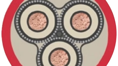
Comprehensive Technical Guide to Norwegian Offshore & Marine Cable Standards

NEK TS 606:2009 Cable Code Designation
Comprehensive Technical Guide to Norwegian Offshore & Marine Cable Standards
Table of Contents
- 1. Introduction to NEK TS 606:2009
- 2. Purpose and Scope
- 3. Cable Code Designation System
- 4. Material Structure and Construction
- 5. Key Characteristics and Features
- 6. Standards Compliance and Certifications
- 7. Safety Thresholds and Testing Requirements
- 8. Installation Precautions and Best Practices
- 9. Common Problems and Troubleshooting
- 10. Industrial Applications
- 11. Conclusion
1. Introduction to NEK TS 606:2009
NEK TS 606:2009 represents the Norwegian offshore industry technical specification (TS) that has become a globally recognized standard for cables used in marine and offshore oil and gas installations. This specification covers a comprehensive range of power, instrumentation, and earth cables that are specifically designed to be halogen-free and mud-resistant, providing critical protection against hydrocarbon-laden drilling liquids commonly encountered in offshore drilling operations.
The Norwegian Electrotechnical Committee (NEK), founded in 1912, manages this specification and serves as an independent organization championing electrotechnical standardization. NEK became the 21st member of the International Electrotechnical Commission (IEC) and is recognized as the national body responsible for standardization in the electrotechnical field. The organizational structure of NEK mirrors that of the IEC in the standardization domain, ensuring international compatibility and recognition.
Historical Background
The predecessor of NEK TS 606 was the publication “Recommended Practice for Specification of Cables” issued by the Norwegian Oil Industry Association (OLF). This specification emerged from the industry’s need to limit and standardize the number of cable types used in the offshore industry during the late 1980s. Since its initial publication in 1993, NEK TS 606 has evolved significantly and secured international acceptance for offshore power, control, and lighting applications.
2. Purpose and Scope
The primary purpose of NEK TS 606:2009 is to provide end users with a comprehensive selection of cables that meet stringent requirements for installation on mobile and fixed offshore units. The specification establishes baseline requirements for halogen-free, low smoke, flame retardant, fire-resistant, and mud-resistant cables across various voltage ranges and applications.
2.1 Coverage Scope
NEK TS 606:2009 encompasses the following cable categories:
Power Cables
Low voltage (LV) and high voltage (HV) power transmission cables rated up to 36 kV for electrical power distribution on offshore platforms and drilling vessels.
Control Cables
Cables designed for control and automation systems, ensuring reliable command transmission in automated offshore operations.
Instrumentation Cables
Precision cables for sensors, measurement devices, and monitoring systems critical to offshore safety and operations.
Lighting Cables
Specialized cables for lighting systems in hazardous offshore environments.
Telecommunication Cables
Data and communication cables for offshore communication infrastructure.
Optical Fiber Cables
High-speed data transmission cables for modern offshore digital systems.
2.2 Enhanced Requirements
NEK TS 606 requirements for oil and mud resistance are significantly more demanding than IEC 60092-360 requirements. The specification mandates enhanced oil resistance testing using test oils IRM902 and IRM903, along with comprehensive mud resistance testing using standardized mud test fluids. These rigorous requirements ensure cable performance in the harsh conditions typical of offshore oil and gas operations.
3. Cable Code Designation System
The NEK TS 606:2009 cable code designation system employs a multi-letter format (typically 2 to 4 letters) to systematically describe cable construction. This standardized naming convention enables industry professionals to quickly identify cable specifications and suitability for specific applications.
3.1 Four-Position Letter System
The complete code designation uses four positions, each representing a specific layer or characteristic of the cable construction:
| Position | Component | Description | Example Letters |
|---|---|---|---|
| 1st Letter | Insulation | Primary conductor insulation material | R, B, T, A, Q, S, I |
| 2nd Letter | Bedding / Inner Sheath | Inner covering or tape layer | F, I, C |
| 3rd Letter | Armour / Screen | Mechanical protection and shielding | O, C, A, X, L |
| 4th Letter | Outer Sheath | External protective jacket | U, I, B |
3.2 Primary Insulation Materials (1st Letter)
| Code | Material | Technical Specification | Key Properties |
|---|---|---|---|
| R | Ethylene Propylene Rubber (EPR) | Synthetic rubber compound | Excellent flexibility, moisture resistance, temperature range -40°C to +90°C |
| B | Fire Resistant Tape + Insulation | Mica glass tape with halogen-free insulation | Fire resistance per IEC 60331-21/31, maintains circuit integrity |
| T | Cross-linked Polyethylene (XLPE) | Thermosetting polymer | High thermal stability, excellent electrical properties, temperature rating up to 90°C |
| I | Thermoplastic Compound | Halogen-free thermoplastic polymer | Good flexibility, cost-effective, temperature rating -30°C to +75°C |
| A | Fibre, Tight Buffered | Optical fiber with protective coating | High-speed data transmission, electromagnetic immunity |
| Q | Fibre in Loose Tube | Optical fiber in gel-filled tube | Enhanced moisture protection, suitable for outdoor applications |
| S | Fire Resistant Silicone | Silicone rubber insulation | Exceptional temperature resistance (-60°C to +180°C), maintains integrity in fire |
3.3 Bedding and Inner Covering (2nd Letter)
| Code | Material | Application |
|---|---|---|
| F | Bedding/Inner Covering or Taping | Halogen-free tape or thermoplastic bedding layer providing cushioning between cores and armor |
| I | Thermoplastic Compound SHF1 | Halogen-free thermoplastic bedding with basic oil resistance |
| C | Polychloroprene (Neoprene) PCP | Chlorinated polyethylene bedding for enhanced chemical resistance |
3.4 Armour and Screen (3rd Letter)
| Code | Material | Protection Type | Mechanical Properties |
|---|---|---|---|
| O | Tinned Copper Wire Braid | Electromagnetic shielding and mechanical protection | Excellent flexibility, tensile strength 1200-1400 N/mm², coverage ≥85% |
| C | Galvanized Steel Wire Braid | Heavy-duty mechanical protection | Superior impact resistance, tensile strength ≥1570 N/mm², coverage ≥90% |
| A | Strength Member of Yarn | Tensile reinforcement for vertical installations | High tensile strength, lightweight, suitable for deep water applications |
| X | No Armour | Unarmoured construction for fixed installation | Maximum flexibility, reduced weight and diameter |
| L | Aluminium (Laminated to Outer Jacket) | Lightweight electromagnetic shielding | Corrosion resistant, good EMI protection, weight reduction up to 40% |
3.5 Outer Sheath Materials (4th Letter)
| Code | Material | Standard Designation | Key Performance Characteristics |
|---|---|---|---|
| U | Thermoset Compound, SHF2 | Enhanced halogen-free thermoset | Mud resistant, enhanced oil resistance, temperature range -40°C to +90°C, flame retardant per IEC 60332-3-22 |
| I | Thermoplastic Compound SHF1 | Standard halogen-free thermoplastic | Good oil resistance, flame retardant, temperature range -30°C to +80°C |
| B | Mud Resistant Thermoplastic Compound | Specialized mud-resistant thermoplastic | Designed for drilling operations, resists hydrocarbon-based mud, temperature rating -30°C to +85°C |
3.6 Additional Abbreviations for Instrumentation Cables
For instrumentation and control cables, additional designations indicate screening configurations:
- (c) – Collective screen: Single screen over all pairs/triples
- (i) – Individual screen: Separate screen for each pair/triple with drain wire
- (i/c) – Individual and collective screen: Combination of both screening types for maximum EMI protection
3.7 Practical Code Examples
Example 1: RFOU Cable
R – EPR insulation (Ethylene Propylene Rubber)
F – Bedding/Inner covering
O – Tinned copper wire braid armour
U – SHF2 mud-resistant outer sheath
Application: Flame retardant power cable for offshore platforms, rated 0.6/1 kV, suitable for general power distribution in hazardous areas.
Example 2: BFOU Cable
B – Fire resistant tape + insulation
F – Bedding/Inner covering
O – Tinned copper wire braid armour
U – SHF2 mud-resistant outer sheath
Application: Fire resistant power cable maintaining circuit integrity per IEC 60331-21/31, critical for emergency systems and evacuation routes.
Example 3: RFOU(i) Cable
R – EPR insulation
F – Bedding/Inner covering
O – Tinned copper wire braid armour
U – SHF2 mud-resistant outer sheath
(i) – Individual pair screening
Application: Instrumentation cable with individual pair screening for high electromagnetic interference (EMI) environments, rated 150/250(300)V.
Example 4: TCXFOU Cable
T – XLPE insulation
C – Polychloroprene bedding
X – No armour
F – Inner covering
O – Tinned copper wire braid screen
U – SHF2 outer sheath
Application: Flexible unarmoured power cable with enhanced chemical resistance for applications requiring frequent movement.
4. Material Structure and Construction
NEK TS 606:2009 cables feature sophisticated multi-layer construction designed to provide comprehensive protection against the unique challenges of offshore environments. Each layer serves specific functional and protective purposes.
4.1 Conductor Specifications
Conductors for cables rated 0.6/1 kV and above must comply with IEC 60228 class 2 (stranded) or class 5 (flexible). The conductor material is typically tinned or bare copper, with specific requirements based on application:
| Conductor Class | Construction | Typical Application | Flexibility Rating |
|---|---|---|---|
| Class 2 | Stranded copper conductors | Fixed installations, power distribution | Standard flexibility |
| Class 5 | Fine-stranded flexible copper | Mobile equipment, reeling applications, VFD cables | High flexibility for repeated bending |
4.2 Insulation Layer Analysis
The insulation layer provides electrical isolation and must withstand voltage stress while maintaining flexibility. Material selection depends on operating conditions:
EPR (Ethylene Propylene Rubber)
Temperature Rating: -40°C to +90°C (continuous), +250°C (short circuit – 5 seconds)
Dielectric Strength: ≥15 kV/mm
Volume Resistivity: ≥10¹³ Ω·m
Advantages: Excellent moisture resistance, superior flexibility at low temperatures, resistant to ozone and UV radiation
XLPE (Cross-linked Polyethylene)
Temperature Rating: -30°C to +90°C (continuous), +250°C (short circuit – 5 seconds)
Dielectric Strength: ≥20 kV/mm
Dielectric Constant: 2.3 (at 50 Hz)
Advantages: Superior electrical properties, excellent thermal stability, lower dielectric losses, higher current carrying capacity
Fire Resistant Insulation (B-Type)
Fire Resistance: 3 hours at 842°C per IEC 60331-21
Circuit Integrity: Maintains operation during fire
Temperature Rating: -40°C to +90°C (normal), survives +842°C (fire conditions)
Application: Emergency systems, fire detection, evacuation lighting
4.3 Screening and Armour Systems
The screening and armour layers provide electromagnetic shielding and mechanical protection. Selection depends on installation environment and EMI requirements:
| Type | Material | Coverage | Tensile Strength | Primary Function |
|---|---|---|---|---|
| Tinned Copper Wire Braid | Tinned copper wires | ≥85% | 1200-1400 N/mm² | EMI shielding, moderate mechanical protection |
| Galvanized Steel Wire Braid | Galvanized steel wires | ≥90% | ≥1570 N/mm² | Heavy mechanical protection, impact resistance |
| Aluminium Tape Screen | Aluminium/polymer laminate | 100% | N/A | EMI/RFI shielding, lightweight construction |
4.4 Outer Sheath Performance Requirements
The outer sheath represents the final line of defense against environmental hazards. NEK TS 606:2009 mandates stringent performance criteria:
SHF2 (Special Halogen-Free 2) Compound Properties
Chemical Composition: Thermosetting elastomer based on ethylene-vinyl acetate (EVA) or ethylene-octene copolymer
Physical Properties:
- Tensile Strength: ≥12.5 N/mm² (per IEC 60092-360)
- Elongation at Break: ≥175%
- Hardness: 85 ± 5 Shore A
- Density: 1.3-1.5 g/cm³
Temperature Performance:
- Minimum Operating Temperature: -40°C (maintains flexibility)
- Maximum Continuous Temperature: +90°C
- Short Circuit Temperature: +250°C (maximum 5 seconds)
Enhanced Oil Resistance: Successfully withstands 168 hours immersion in IRM902 and IRM903 test oils at 100°C with <5% change in tensile properties
Mud Resistance: Passes 168 hours exposure to standardized drilling mud at 80°C per NEK 606 Annex requirements
5. Key Characteristics and Features
NEK TS 606:2009 cables are engineered with multiple advanced characteristics that distinguish them from standard industrial cables. These features ensure reliable performance in the demanding offshore environment.
5.1 Halogen-Free Low Smoke (HFLS) Properties
In the event of a fire, halogen-free cables produce significantly less smoke and eliminate toxic fumes, ensuring crew safety and equipment protection. This characteristic is critical in confined offshore spaces where evacuation routes must remain visible and breathable.
Smoke Density
Test Standard: IEC 61034-2
Requirement: Light transmittance ≥60%
Significance: Ensures visibility during emergency evacuation
Halogen Content
Chlorine Content: <0.2%
Fluorine Content: <0.2%
Total Halogens: <0.5%
Benefit: No corrosive or toxic halogen gases during combustion
Acidity of Gases
Test Standard: IEC 60754-2
pH Value: ≥4.3
Conductivity: ≤10 μS/mm
Importance: Prevents corrosive damage to electronic equipment and structures
5.2 Flame Retardancy and Fire Resistance
NEK TS 606 distinguishes between flame retardant and fire resistant cables, each serving critical but different safety functions:
| Property | Flame Retardant (RFOU) | Fire Resistant (BFOU) |
|---|---|---|
| Test Standard | IEC 60332-3-22 (Category A) | IEC 60331-21 and IEC 60331-31 |
| Purpose | Prevents fire propagation along cable route | Maintains circuit integrity during fire |
| Test Duration | 40 minutes vertical flame test | 3 hours at 842°C with mechanical impact |
| Performance Requirement | Total burnt length <2.5m, no burning debris | Continues operation throughout fire exposure |
| Typical Application | General power and control systems | Emergency power, fire detection, evacuation systems |
5.3 Oil and Mud Resistance
NEK TS 606 oil and mud resistance requirements exceed those specified in IEC 60092-360, reflecting the harsher conditions encountered in offshore drilling operations. All SHF2 sheathed cables must demonstrate both enhanced oil resistance and mud resistance where specified.
Enhanced Oil Resistance Testing Protocol
Test Method: IEC 60092-360 SHF2 requirements
Test Oils: IRM902 (aliphatic hydrocarbon) and IRM903 (aromatic hydrocarbon)
Test Conditions:
- Duration: 168 hours (7 days) continuous immersion
- Temperature: 100°C ± 2°C
- Sample conditioning: 16 hours at 23°C after removal
Acceptance Criteria:
- Tensile strength change: <25%
- Elongation at break change: <25%
- Volume change: <20%
- No visible cracking, swelling, or delamination
Mud Resistance Testing Protocol
Test Method: NEK 606 Annex C requirements
Test Fluid: Standardized oil-based drilling mud (EDC 95-11 base)
Test Conditions:
- Duration: 168 hours continuous exposure
- Temperature: 80°C ± 2°C
- Mud composition: Specific formulation per NEK 606 Table 1c
Acceptance Criteria:
- Tensile strength change: <30%
- Elongation at break change: <30%
- Weight change: <15%
- Sheath must remain intact with no penetration to inner layers
Note: When field-specific mud compositions deviate from NEK 606 standard test fluids, special evaluation or additional testing may be required by agreement between supplier and end user.
5.4 Electromagnetic Compatibility (EMC)
Offshore installations contain sensitive instrumentation and control systems requiring protection from electromagnetic interference. NEK TS 606 cables incorporate various screening configurations to ensure EMC compliance:
- Individual Pair Screening (i): Each signal pair has its own foil or braid screen with drain wire, providing maximum isolation for critical measurement circuits. Transfer impedance <50 mΩ/m at 1 MHz.
- Collective Screening (c): Single overall screen covers all pairs/triples, suitable for moderate EMI environments. Screening effectiveness ≥70 dB at frequencies 10 kHz to 1 GHz.
- Individual + Collective Screening (i/c): Combines both methods for maximum protection in severe EMI environments such as variable frequency drive (VFD) installations. Total screening effectiveness ≥85 dB.
6. Standards Compliance and Certifications
NEK TS 606:2009 cables must comply with multiple international standards and obtain certifications from recognized classification societies. This multi-layered compliance framework ensures cables meet the rigorous requirements of offshore and marine applications.
6.1 Primary Standards Framework
| Standard | Title | Scope | Key Requirements |
|---|---|---|---|
| NEK TS 606:2009 | Technical Specification for Offshore Cables | Complete cable specifications for offshore applications | Enhanced oil/mud resistance, HFLS properties, specific construction requirements |
| IEC 60092-350 | Electrical installations in ships – Part 350: General construction and test methods | Basic requirements and test methods | Voltage ratings, temperature limits, basic electrical properties |
| IEC 60092-353 | Power cables for rated voltages 1 kV and 3 kV | Low voltage power cable specifications | Construction, dimensions, electrical characteristics |
| IEC 60092-360 | Insulating and sheathing materials for shipboard cables | Material performance requirements | Oil resistance, temperature stability, mechanical properties |
| IEC 60092-376 | Shipboard control and instrumentation cables | Instrumentation cable specifications | Screening effectiveness, pair construction, voltage ratings |
| IEC 60228 | Conductors of insulated cables | Conductor specifications and classifications | Conductor sizes, stranding classes, resistance values |
6.2 Fire Safety Standards
| Standard | Test Description | Application |
|---|---|---|
| IEC 60331-21 | Circuit integrity test for cables rated ≤0.6/1 kV | Fire resistant cables (BFOU) – maintains operation at 842°C for 3 hours |
| IEC 60331-31 | Circuit integrity test for cables rated >0.6/1 kV | Fire resistant power cables – medium voltage applications |
| IEC 60332-1-2 | Single vertical cable flame propagation test | Earth cables and single conductor cables |
| IEC 60332-3-22 | Vertical flame propagation test for bunched cables (Category A) | Flame retardant cables (RFOU) – prevents fire spread in cable bundles |
| IEC 61034-2 | Smoke density test (3-meter cube method) | All halogen-free cables – ensures visibility during evacuation |
| IEC 60754-1 | Determination of halogen acid gas content | Verification of halogen-free claim |
| IEC 60754-2 | Acidity and conductivity of combustion gases | Assessment of corrosive potential during fire |
6.3 Classification Society Approvals
NEK TS 606 cables manufactured by certified suppliers are approved by major international classification societies, ensuring they meet stringent maritime and offshore industry requirements. Required approvals include:
DNV (Det Norske Veritas)
Norwegian classification society specializing in offshore and maritime certification. Type approval required for all NEK 606 cables.
ABS (American Bureau of Shipping)
Required for installations in US offshore operations and vessels flying US flags. Product design assessment and factory inspection mandatory.
Lloyd’s Register (LR)
British classification society with global recognition. Type approval certificate demonstrates compliance with international marine standards.
CCS (China Classification Society)
Required for offshore installations and vessels operating in Chinese waters or built in Chinese shipyards.
6.4 Quality Management System Requirements
Manufacturers of NEK 606 cables must maintain certification to ISO 9001 (Quality Management) and ISO 14001 (Environmental Management). These certifications ensure consistent manufacturing processes and environmental responsibility throughout production.
7. Safety Thresholds and Testing Requirements
NEK TS 606:2009 establishes comprehensive safety thresholds and mandatory testing protocols to ensure cable reliability in critical offshore applications. These requirements significantly exceed those of standard industrial cables.
7.1 Electrical Safety Parameters
| Parameter | Voltage Rating | Threshold Value | Test Standard |
|---|---|---|---|
| Insulation Resistance (at 20°C) | 0.6/1 kV | ≥100 MΩ·km | IEC 60092-350 |
| Insulation Resistance (at 20°C) | 3.6/6 kV to 8.7/15 kV | ≥500 MΩ·km | IEC 60092-350 |
| AC Voltage Test (5 minutes) | 0.6/1 kV | 3.5 kV | IEC 60092-350 |
| AC Voltage Test (5 minutes) | 3.6/6 kV | 15 kV | IEC 60092-350 |
| Partial Discharge Test | ≥3.6/6 kV | <10 pC at 1.5 Uo | IEC 60885-3 |
| Conductor DC Resistance (20°C) | All voltages | Per IEC 60228 | IEC 60228 |
| Screening/Armor Resistance | Screened cables | ≤10 Ω/km | IEC 60092-376 |
7.2 Mechanical Performance Thresholds
| Property | Test Condition | Minimum Requirement | Test Method |
|---|---|---|---|
| Tensile Strength (insulation) | Before aging | ≥12.5 N/mm² (EPR), ≥15 N/mm² (XLPE) | IEC 60092-360 |
| Elongation at Break (insulation) | Before aging | ≥175% (EPR), ≥200% (XLPE) | IEC 60092-360 |
| Tensile Strength (sheath) | After thermal aging | ≥80% of initial value | IEC 60092-360 |
| Cold Bend Test | -40°C for 16 hours | No cracks visible at 7× magnification | IEC 60092-360 |
| Impact Resistance (sheath) | -40°C | No cracks after 10J impact | IEC 60092-360 |
| Abrasion Resistance | Standard conditions | ≥100 cycles without conductor exposure | IEC 60092-360 |
7.3 Environmental Durability Requirements
Thermal Aging Resistance
Test Duration: 168 hours at maximum rated temperature +15°C
Requirement: Retention of ≥80% tensile strength and ≥75% elongation
Standard: IEC 60092-360
Water Absorption
Test Duration: 7 days immersion at 70°C
Requirement: Change in tensile properties <15%, insulation resistance maintained
Standard: IEC 60092-360
Ozone Resistance
Test Conditions: 40°C, 200 pphm ozone, 20% elongation
Duration: 96 hours
Requirement: No visible cracks
UV Resistance
Test: 720 hours accelerated weathering
Requirement: Retention of ≥75% mechanical properties
Application: Cables for outdoor installations
7.4 Current Carrying Capacity
Maximum continuous current ratings are determined by conductor temperature limits and installation method. The following table provides typical values for NEK TS 606 power cables:
| Conductor Size (mm²) | Current Rating (A) – Single Core in Air | Current Rating (A) – Three Core in Air | Current Rating (A) – Buried/Conduit |
|---|---|---|---|
| 1.5 | 24 | 20 | 19 |
| 2.5 | 32 | 27 | 25 |
| 4 | 42 | 36 | 33 |
| 6 | 54 | 46 | 42 |
| 10 | 73 | 63 | 57 |
| 16 | 98 | 85 | 76 |
| 25 | 129 | 112 | 100 |
| 35 | 158 | 137 | 122 |
| 50 | 192 | 167 | 148 |
| 70 | 240 | 209 | 185 |
| 95 | 289 | 252 | 223 |
| 120 | 334 | 291 | 257 |
| 150 | 382 | 333 | 294 |
| 185 | 441 | 384 | 339 |
| 240 | 530 | 461 | 407 |
| 300 | 626 | 545 | 481 |
Note: Values are for EPR/XLPE insulated cables at 90°C conductor temperature, 40°C ambient, and specific installation conditions. Derating factors must be applied for different ambient temperatures, grouping, or thermal resistivity of soil.
8. Installation Precautions and Best Practices
Proper installation of NEK TS 606:2009 cables is essential to ensure long-term reliability and safety in offshore environments. The following precautions and best practices should be strictly observed during handling, installation, and maintenance.
8.1 Storage and Handling Requirements
Critical Storage Guidelines
- Temperature Range: Store cables between -25°C and +55°C to prevent insulation damage
- Humidity Control: Maximum 85% relative humidity; use dehumidification in tropical climates
- UV Protection: Store indoors or under UV-resistant covers; prolonged sunlight exposure degrades sheath materials
- Drum Storage: Position cable drums vertically when possible to prevent flange damage; ensure drums are blocked to prevent rolling
- Shelf Life: Install within 24 months of manufacture date; inspect insulation resistance before installation if storage exceeds 12 months
- Chemical Isolation: Store away from acids, alkalis, petroleum products, and oxidizing agents that may degrade materials
8.2 Minimum Bending Radius Requirements
Excessive bending causes insulation damage, conductor strain, and armour distortion. Adhere to these minimum bending radii during installation:
| Cable Type | Minimum Bending Radius (Installation) | Minimum Bending Radius (Fixed Installation) | Notes |
|---|---|---|---|
| Armoured Power Cable (Single Core) | 15 × OD | 12 × OD | OD = Overall Diameter |
| Armoured Power Cable (Multi-Core) | 12 × OD | 10 × OD | Reduced stress on multi-core construction |
| Unarmoured Power Cable | 8 × OD | 6 × OD | Greater flexibility without armour |
| Instrumentation Cable (Armoured) | 12 × OD | 10 × OD | Critical for maintaining EMI shielding |
| Control Cable (Unarmoured) | 6 × OD | 5 × OD | Suitable for cable tray installations |
| Flexible Class 5 Conductor Cables | 5 × OD | 4 × OD | For reeling and mobile applications |
8.3 Installation Temperature Considerations
Temperature-Dependent Installation Procedures
Minimum Installation Temperature: Do not install cables below -20°C. At temperatures below 0°C, cable insulation and sheath materials become less flexible, increasing risk of damage.
Cold Weather Procedures:
- Pre-condition cables in heated storage area for minimum 24 hours before installation
- Use heated installation tents or enclosures in extreme cold conditions
- Reduce installation pulling speeds by 50% when ambient temperature is below 0°C
- Increase minimum bending radius by 25% for installations at temperatures below 0°C
Hot Weather Procedures:
- Avoid direct sunlight on cable drums; provide shade or reflective covers
- Do not install if cable surface temperature exceeds 60°C
- Allow cables to acclimate to installation temperature for 4 hours before tension-sensitive operations
8.4 Cable Pulling and Installation Techniques
Maximum Pulling Tension
Copper Conductors: 50 N/mm² of conductor cross-section
Aluminum Conductors: 25 N/mm² of conductor cross-section
Monitoring: Use tension monitoring equipment; never exceed 80% of maximum allowable tension
Pulling Speed
Standard Conditions: Maximum 15 meters/minute
Complex Routes: Reduce to 8 meters/minute for multiple bends or long pulls >100m
Caution: Excessive speed generates heat from friction, potentially damaging insulation
Lubrication Requirements
Approved Lubricants: Use only cable-pulling compounds compatible with SHF2 sheath materials
Application: Apply to cable surface and conduit interior; avoid contamination of cable ends
Prohibited: Petroleum-based products, silicone oils, soap solutions
Conduit Fill Ratio
Single Cable: Cable area ≤40% of conduit area
Multiple Cables: Total cable area ≤35% of conduit area
Reason: Allows heat dissipation and prevents sidewall pressure damage during pulling
8.5 Support and Fixing Methods
- Cable Tray Installation: Support cables every 1.5m for horizontal runs; use cable cleats at 0.75m intervals for vertical runs to prevent sliding under own weight
- Cleat Spacing for Fire-Rated Cables: Maximum 600mm spacing for fire resistant (BFOU) cables to maintain circuit integrity during fire conditions
- Armoured Cable Support: Do not rely solely on armour for cable support; use cable cleats that grip the outer sheath without compressing the cable
- Heavy Cable Support: For cables >50mm diameter, install intermediate supports every 1.0m on horizontal cable trays
- Vertical Run Support: Use cable grips specifically designed for vertical installations; maximum unsupported span: 2.5m for armoured cables, 1.5m for unarmoured cables
- Expansion and Contraction: Allow 6mm expansion/contraction per 10m cable length per 10°C temperature change; use expansion loops or flexible sections in long cable runs
8.6 Termination and Connection Practices
Critical Termination Requirements
Cable Preparation:
- Remove sheath and armour using proper stripping tools; avoid using knives that may score insulation
- Maintain minimum 25mm separation between exposed armor end and cable gland entry
- Apply armour termination tape to prevent corrosion of exposed metal components
- Seal cable ends immediately after cutting to prevent moisture ingress
Gland Selection:
- Use only cable glands certified for marine/offshore use with appropriate ATEX/IECEx certification for hazardous areas
- Ensure gland size matches cable outer diameter; undersized glands prevent proper sealing
- Armoured cables require glands with armor clamping capability to maintain mechanical continuity
- For screened instrumentation cables, use glands that provide 360° EMC continuity
Connections:
- Use crimp connectors rated for operating temperature of cable (minimum 90°C for NEK 606 cables)
- Apply recommended crimping force per connector manufacturer specifications; verify crimp quality using pull test
- Do not mix aluminum and copper conductors without appropriate bi-metallic connectors
- Apply anti-oxidant compound to aluminum conductors before termination
- Label all connections with cable identification matching installation drawings
8.7 Hazardous Area Considerations
When installing NEK TS 606 cables in classified hazardous areas (ATEX/IECEx Zones 0, 1, 2 or Division 1, 2), additional precautions apply:
- Cable Gland Certification: All cable glands must have appropriate ATEX/IECEx certification matching the zone classification
- Ingress Protection: Minimum IP66 rating for cable terminations in outdoor hazardous areas; IP67 or IP68 for areas with washing or submersion risk
- Stopping Compound: Use certified stopping compound to seal multi-core cable entries and prevent gas migration through cable cores
- Earthing Continuity: Establish and verify continuous earth path through armour/screen connections; maximum earth loop resistance: 1Ω
- Intrinsically Safe Circuits: Maintain minimum separation of 50mm between intrinsically safe cables (blue sheath) and non-IS cables; use separate cable trays where possible
8.8 Testing After Installation
Comprehensive testing validates installation integrity before energization:
| Test Type | Procedure | Acceptance Criteria | Frequency |
|---|---|---|---|
| Visual Inspection | Examine for physical damage, proper support, correct routing | No visible damage, compliant with installation drawings | 100% of installation |
| Continuity Test | Verify conductor continuity using multimeter | Resistance matches calculated value ±5% | All conductors |
| Insulation Resistance | Apply 1000V DC for 1 minute (0.6/1kV cables) | ≥100 MΩ·km for power cables, ≥10 MΩ·km for control/instrumentation | All circuits |
| High Voltage Test (Optional) | Apply 80% of factory test voltage for 1 minute | No breakdown or excessive leakage current | Critical circuits only |
| Screen/Armor Continuity | Verify continuous earth path through screens and armors | Resistance <10 Ω from end to end | All screened/armoured cables |
| Phasing Test | Verify correct phase rotation for three-phase circuits | A-B-C rotation confirmed | All 3-phase power circuits |
9. Common Problems and Troubleshooting
Understanding typical failure modes and their solutions enables efficient maintenance and extends cable service life in offshore installations.
9.1 Insulation Degradation Issues
| Problem | Symptoms | Causes | Solutions |
|---|---|---|---|
| Moisture Ingress | Decreasing insulation resistance, intermittent faults, corrosion at terminations | Damaged sheath, poor gland sealing, missing end caps during storage | Replace damaged cable section, re-terminate with certified glands, ensure proper sealing. For stored cables, test IR before installation and reject if <50% of specification |
| Thermal Overload | Brittle insulation, discoloration, burning odor, reduced flexibility | Sustained overcurrent, inadequate heat dissipation, incorrect cable sizing | Verify actual load vs. cable rating; check for cable bundling reducing heat dissipation; install cables with appropriate derating factors. Replace thermally damaged cables. |
| Chemical Attack | Sheath swelling, surface cracking, color change, loss of mechanical strength | Exposure to incompatible chemicals, drilling fluid contamination, hydraulic oil leaks | Identify contamination source; reroute cables away from chemical exposure areas. For ongoing exposure, upgrade to cables with enhanced chemical resistance or install protective conduit. |
| Partial Discharge | Progressive insulation failure, ozone smell, elevated temperatures, eventual breakdown | Installation damage, contamination during termination, moisture in voids, sharp metallic edges | Conduct partial discharge testing on HV cables; locate and repair defective terminations. Ensure cleanliness during HV cable terminations; use stress control accessories. |
9.2 Mechanical Damage Problems
| Problem | Symptoms | Prevention/Resolution |
|---|---|---|
| Overbending Damage | Visible kinks, armor buckling, conductor strand breakage, localized heating | Verify minimum bending radius compliance during installation review. Install cable guides at tight bends. Replace sections with visible damage. Train installation personnel on proper handling. |
| Crush Damage | Flattened cable appearance, sheath cracks, conductor deformation, intermittent operation | Use cable covers in areas with vehicle traffic. Install protective conduit in high-risk zones. Ensure adequate support prevents sagging that may be stepped on. Replace crushed sections. |
| Abrasion Wear | Worn sheath, exposed armor, visible strands, reduced protection rating | Identify vibration sources causing cable movement against edges. Install anti-chafe sleeves or cable guides. Reroute cables to avoid sharp edges. For reeling cables, inspect drums for burrs or damage. |
| Pulling Damage | Stretched conductors, elongated cable, damaged armor, pulled-apart terminations | Verify pulling tension did not exceed limits. Use proper pulling grips that distribute load. Never pull cables by their terminations. For long pulls, use intermediate pulling points. Test IR after installation. |
9.3 Environmental Degradation
UV Degradation
Indicators: Surface chalking, color fading, microcracking, reduced flexibility
Prevention: Install cables in conduit or cable tray with covers for outdoor runs; use UV-resistant outer sheath for unavoidable sun exposure
Remediation: Assess remaining service life through tensile testing; apply UV-protective wraps or replace if degradation >25%
Corrosion (Armour/Screen)
Indicators: Rust spots, armor wire breakage, loss of mechanical strength, compromised EMC shielding
Prevention: Proper gland selection maintaining armor seal; apply corrosion inhibitor to cut armor ends; use tinned copper braid in highly corrosive areas
Remediation: If corrosion affects <20% of armor cross-section, monitor regularly; if >20%, consider replacement as mechanical integrity compromised
Biological Attack
Indicators: Termite damage (tropical climates), rodent gnaw marks, bacterial degradation of sheath
Prevention: Install cables in sealed metallic conduit in areas with known pest activity; use armoured construction; maintain facility pest control programs
Remediation: Replace damaged sections immediately; install physical barriers; consider upgrading to more resistant cable types
Cold Temperature Embrittlement
Indicators: Sheath cracking in cold conditions, reduced flexibility, fracture during minimal movement
Prevention: Specify cables with -40°C rating for installations in cold climates; avoid mechanical stress during cold periods
Remediation: If cracking observed, assess whether temperature exceeded cable rating; may require replacement with cold-rated cable type
9.4 Operational Issues
Electromagnetic Interference (EMI) Problems
Symptoms: Erratic instrumentation readings, control system malfunctions, communication errors, unexplained sensor fluctuations
Diagnostic Approach:
- Verify screen continuity and proper earthing at one end only (avoid ground loops)
- Check for parallel routing with power cables, especially VFD circuits
- Measure EMI levels using spectrum analyzer to identify interference sources
- Confirm proper cable type selection (individual vs. collective screening)
Corrective Actions:
- Increase separation between instrumentation and power cables to ≥300mm
- Use cable tray segregation (instrumentation and power on separate trays)
- Install EMI filters on VFD circuits
- Upgrade to cables with individual pair screening (i) for critical measurement circuits
- Verify all screen terminations maintain 360° EMC continuity
Voltage Drop and Power Quality Issues
Symptoms: Equipment undervoltage alarms, motor starting difficulties, lighting flickering, overheating at connections
Analysis:
- Calculate actual voltage drop: Vdrop = √3 × I × (R cos φ + X sin φ) × L
- Measure voltage at load terminals under full load conditions
- Verify connections are tight and not overheating (use thermal imaging)
- Check for undersized cable relative to actual load
Solutions:
- If voltage drop >3% for power circuits or >5% for lighting, consider cable replacement with larger size
- Install parallel cables to increase effective conductor size
- Verify load calculations included proper demand factors and future expansion
- Check for high-resistance connections; remake or replace
9.5 Diagnostic Testing Procedures
| Test Method | Application | Interpretation | Action Threshold |
|---|---|---|---|
| Insulation Resistance Trending | Monitor cable aging and moisture ingress | Declining trend indicates progressive failure; sudden drop suggests damage event | If IR drops below 50% of baseline or <1 MΩ·km, investigate immediately |
| Time Domain Reflectometry (TDR) | Locate cable faults, measure cable length, identify splice locations | Impedance discontinuities indicate damage, water ingress, or poor joints | Use to pinpoint exact fault location before excavation/repair |
| Partial Discharge Testing | Detect insulation degradation in HV cables (≥3.6kV) | PD magnitude >100pC indicates significant defects requiring attention | Trending PD increase suggests progressive failure; plan replacement |
| Thermographic Inspection | Identify overheating connections, overloaded circuits, phase imbalance | Hot spots >20°C above ambient suggest high-resistance connections or overload | Temperature rise >30°C requires immediate investigation and repair |
| Tan Delta (Dissipation Factor) | Assess insulation quality in medium/high voltage cables | Increasing tan δ indicates moisture or insulation deterioration | Tan δ >2% or 50% increase from baseline warrants detailed assessment |
9.6 Preventive Maintenance Program
Implement systematic preventive maintenance to maximize cable service life:
- Visual Inspections (Monthly): Check for physical damage, water accumulation in cable trenches, loose supports, signs of overheating
- Thermographic Survey (Annual): Infrared inspection of all terminations and connections under load to identify developing hot spots
- Insulation Resistance Testing (Annual): Test and record IR values to establish trending data; compare with previous readings
- Cleaning (Annual): Remove dust, oil, and salt deposits from cable surfaces; clean terminations and glands
- Tightness Check (Biennial): Verify torque on all accessible connections; remake if found loose
- Comprehensive Testing (5 Years): Detailed electrical testing including high-voltage tests, partial discharge assessment for HV cables
- Documentation: Maintain detailed records of all tests, inspections, repairs, and modifications to enable trending and predictive maintenance
10. Industrial Applications
NEK TS 606:2009 cables serve critical functions across diverse offshore and marine installations. Understanding application-specific requirements ensures optimal cable selection and installation.
10.1 Offshore Oil & Gas Platforms
NEK 606 cables are designed to withstand harsh and hazardous area operating conditions of the global oil and gas industry, providing reliable power, control, and instrumentation throughout offshore facilities.
Production Platform Applications
Power Distribution: RFOU/BFOU 0.6/1kV to 36kV cables for main power distribution from generators to process equipment
Process Control: RFOU(c) cables for distributed control systems (DCS), programmable logic controllers (PLC), and SCADA systems
Instrumentation: RFOU(i) cables for pressure transmitters, temperature sensors, flow meters in classified hazardous areas
Drilling Operations
Mud-Resistant Cables: SHF2 MUD sheathed cables for drilling equipment exposed to hydrocarbon-based drilling fluids
VFD Applications: RFOU-VFD cables with Class 5 flexible conductors for top drive systems, drawworks, and mud pumps
Emergency Systems: BFOU fire-resistant cables for emergency shutdown (ESD) systems maintaining operation during fire
Accommodation Modules
Lighting Circuits: RFOU cables for general and emergency lighting in living quarters
Fire Detection: BFOU cables for smoke detectors and fire alarm systems requiring circuit integrity
Communication: RFOU instrumentation cables for telephone, PA systems, and emergency communication networks
Subsea Connections
Umbilicals: Specialized NEK 606 compliant cables incorporated into subsea control umbilicals
ROV Applications: Flexible NEK 606 cables for remotely operated vehicle tethers and power supplies
Deepwater: Cables with strength members (A-type armour) for vertical installations in deep water
10.2 Floating Production Storage and Offloading (FPSO) Vessels
FPSO installations combine ship and platform characteristics, requiring cables that accommodate both marine vessel standards and offshore process requirements:
- Dynamic Positioning Systems: High-reliability RFOU(i) instrumentation cables for DP thrusters and control systems ensuring vessel station keeping
- Turret Mooring Systems: Flexible cables through rotating turret requiring enhanced fatigue resistance and flexibility
- Process Systems: Same requirements as fixed platforms but with additional consideration for vessel motion and vibration
- Cargo Systems: Cables exposed to crude oil vapors requiring enhanced hydrocarbon resistance
10.3 Offshore Wind Installations
While NEK TS 606 originated for oil & gas, its robust specifications make it suitable for offshore wind farms:
- Turbine Internal Wiring: RFOU power and control cables for nacelle and tower installations
- Array Cables: Medium voltage BFOU cables connecting turbines to offshore substations
- Platform Distribution: Power and control cables for offshore converter platforms and substations
- Advantage Over Standard Cables: Superior environmental resistance, flame retardancy, and halogen-free properties ideal for unmanned offshore structures
10.4 Marine Vessel Applications
NEK TS 606 cables meet requirements for specialized marine vessels operating in offshore support roles:
| Vessel Type | Cable Applications | Specific Requirements |
|---|---|---|
| Offshore Supply Vessels (OSV) | Main propulsion, bow thrusters, dynamic positioning, cargo handling systems | Vibration resistance, flexibility for engine room routing, DP classification compliance |
| Anchor Handling Tug Supply (AHTS) | High-power winch drives, towing systems, VFD motor controls | Enhanced mechanical protection, flexible Class 5 conductors for moving equipment |
| Accommodation Vessels | Hotel services, HVAC systems, galley equipment, life safety systems | Fire resistance for escape routes, low smoke for confined spaces, SOLAS compliance |
| Cable Laying Vessels | Dynamic positioning, specialized cable handling equipment, subsea deployment systems | High reliability, redundant systems requiring segregated cable routing |
| Drill Ships | Drilling equipment, mud pumps, top drives, well control systems | Mud-resistant cables, fire-resistant emergency systems, dynamic positioning critical circuits |
10.5 Comparison with Related Cable Systems
Understanding how NEK TS 606:2009 compares with other specialized cable systems helps in application selection. For comprehensive information about other industrial cable applications, including reeling cables for mobile machinery, AS/NZS mining cables for Australian operations, and specialized port crane cables, manufacturers like Anhui Feichun Special Cable Co., Ltd. offer complete cable solutions. Additionally, mining cable solutions for Latin American operations demonstrate the global reach of specialized cable manufacturing.
11. Conclusion
NEK TS 606:2009 represents a comprehensive and demanding technical specification that has established itself as the global benchmark for cables used in offshore oil and gas installations, marine vessels, and other harsh environment applications. The sophisticated cable code designation system enables precise specification of cable construction, ensuring each application receives cables with appropriate characteristics for reliable long-term operation.
The multi-letter code designation system systematically describes every critical aspect of cable construction from conductor insulation through outer sheath material. This standardization facilitates clear communication between specifiers, manufacturers, and installers while ensuring consistency across projects and facilitating spare parts procurement throughout the cable lifecycle.
Key Takeaways
- Enhanced Safety: Halogen-free construction eliminates toxic and corrosive gases during fire, protecting personnel and equipment in confined offshore environments
- Environmental Resistance: Superior oil and mud resistance exceeding IEC 60092-360 requirements ensures reliable operation in drilling operations and hydrocarbon-rich environments
- Fire Performance: Distinct flame retardant (RFOU) and fire resistant (BFOU) cable types provide appropriate protection levels for different applications
- International Recognition: Acceptance by major classification societies (DNV, ABS, Lloyd’s Register, CCS) facilitates global project deployment
- Comprehensive Testing: Rigorous qualification and routine testing protocols ensure consistent quality and performance
Proper cable selection using the NEK TS 606:2009 designation system, combined with adherence to installation best practices and implementation of systematic preventive maintenance programs, ensures optimal cable performance throughout the demanding service life in offshore and marine environments. The investment in high-quality NEK 606 compliant cables delivers superior reliability, enhanced safety, and reduced total cost of ownership compared to standard industrial cable alternatives.
As offshore operations extend into increasingly challenging environments including ultra-deep water, Arctic conditions, and harsh weather zones, the robust specifications of NEK TS 606:2009 continue to provide the foundation for safe and reliable electrical installations supporting critical offshore infrastructure worldwide.
Contact Anhui Feichun Special Cable Co., Ltd.
For professional consultation on NEK TS 606:2009 cable selection and supply