
H07RN8-F Submersible Cable
Harmonized Rubber Cable for Underwater Pump Applications
450/750V | Water Depth: 10m | Temperature: up to 40°C
Anhui Feichun Special Cable Co., Ltd. – Engineered for Submersible Excellence
Technical Overview & Performance Metrics
Engineered for Submersible Excellence
The H07RN8-F represents the pinnacle of harmonized rubber cable technology, specifically engineered for continuous submersion in industrial water environments. This specialized cable employs advanced elastomeric compounds conforming to DIN VDE 0282 Part 16, ensuring reliable power transmission in challenging aquatic conditions where conventional cables would fail catastrophically.
Core Engineering Advantages
Hydrostatic Pressure Resistance
Withstands continuous pressure up to 1 bar (10m water column) without deformation or electrical degradation. The multi-layer rubber construction maintains dimensional stability under cyclic pressure variations typical in pump operation.
Water Ingress Protection
Specialized EM2 rubber compound provides IPX8 protection level. Molecular cross-linking prevents water molecule penetration even under prolonged submersion, maintaining insulation resistance >100 MΩ/km after 1000 hours immersion.
Chemical Resilience
Resistant to industrial water contaminants including chlorides, sulfates, and moderate pH variations (5.5-9.0). The EI4 insulation compound resists hydrolysis and maintains mechanical properties in mineralized water environments.
Advanced Cable Construction Architecture
Layer-by-Layer Construction Analysis
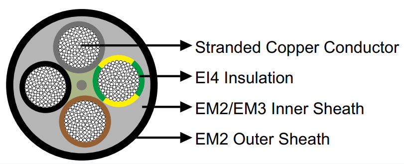
1. Conductor System (Core)
- Material: Electrolytic copper, purity >99.95%
- Configuration: Class 5 flexible stranded per IEC 60228
- Stranding: Concentric lay, maximum lay length 30×OD
- Surface treatment: Tin-plated option for enhanced corrosion resistance
2. Primary Insulation (EI4 Compound)
- Composition: Ethylene-propylene rubber (EPR) based
- Dielectric strength: >20 kV/mm
- Temperature index: 90°C continuous, 250°C short circuit (5s)
- Elongation at break: >200% per IEC 60811
3. Inner Sheath (EM2/EM3 – for ≥10mm² or >5 cores)
- Function: Mechanical separation and circular form maintenance
- Material: Polychloroprene-based rubber compound
- Thickness calculation: 0.035D + 0.8mm (D = laid-up core diameter)
4. Outer Sheath (EM2 Compound)
- Type: Heavy-duty polychloroprene rubber
- Properties: Oil-resistant, weather-resistant, ozone-resistant
- Tensile strength: >10 N/mm²
- Abrasion resistance: <150 mm³ per DIN 53516
Comprehensive Dimensional Data & Specifications
Single Core & Multi-Core Configurations
| Configuration | Insulation (mm) | Inner Sheath (mm) | Outer Sheath (mm) | Min OD (mm) | Max OD (mm) | Weight (kg/km) |
|---|---|---|---|---|---|---|
| 1×1.5 mm² | 0.8 | – | 1.4 | 5.7 | 6.7 | 60 |
| 3G1.5 mm² | 0.8 | – | 1.6 | 9.2 | 11.2 | 170 |
| 4G2.5 mm² | 0.9 | – | 1.9 | 12.1 | 14.5 | 290 |
| 5G4 mm² | 1.0 | – | 2.2 | 15.6 | 19.0 | 505 |
| 4G6 mm² | 1.0 | – | 2.3 | 15.7 | 19.0 | 550 |
| 3G10 mm² | 1.2 | 1.3 | 2.0 | 19.1 | 22.5 | 715 |
| 5G16 mm² | 1.2 | 1.5 | 2.4 | 26.4 | 31.0 | 1610 |
| 4G25 mm² | 1.4 | 1.6 | 2.2 | 28.9 | 33.0 | 1890 |
| 4G35 mm² | 1.4 | 1.7 | 2.7 | 32.5 | 36.5 | 2505 |
| 4G50 mm² | 1.6 | 1.9 | 2.9 | 37.7 | 42.0 | 3350 |
| 4G70 mm² | 1.6 | 2.0 | 3.2 | 42.7 | 47.0 | 4785 |
| 4G95 mm² | 1.8 | 2.3 | 3.6 | 48.4 | 54.0 | 6090 |
| 4G120 mm² | 1.8 | 2.4 | 3.6 | 53.0 | 59.0 | 7550 |
| 4G150 mm² | 2.0 | 2.6 | 3.9 | 58.0 | 64.0 | 8495 |
Large Single Core Specifications
| Cross Section | Insulation (mm) | Outer Sheath (mm) | Min OD (mm) | Max OD (mm) | Weight (kg/km) |
|---|---|---|---|---|---|
| 1×185 mm² | 2.2 | 3.4 | 27.6 | 31.5 | 2230 |
| 1×240 mm² | 2.4 | 3.5 | 30.6 | 35.0 | 2945 |
| 1×300 mm² | 2.6 | 3.6 | 33.5 | 38.0 | 3495 |
| 1×630 mm² | 3.0 | 4.1 | 45.5 | 51.0 | 7020 |
Water Performance & Submersible Characteristics
Hydro-Performance Testing Results
Immersion Endurance Test
Standard: HD 22.16 S1 Clause 5.4
Conditions: 1000 hours at 40°C, 1 bar pressure
Results:
- Insulation resistance: >500 MΩ·km
- Dielectric strength retention: 98%
- Volume resistivity: >10¹³ Ω·cm
Dynamic Pressure Cycling
Test protocol: 0-1.5 bar, 10,000 cycles
Frequency: 1 cycle/minute
Performance metrics:
- No jacket delamination
- Maintained flexibility: <15% stiffness increase
- Zero electrical degradation
Water Quality Tolerance
pH range: 5.5 – 9.0
Salinity: Up to 3000 ppm TDS
Contaminants tolerated:
- Chlorides: <500 ppm
- Sulfates: <200 ppm
- Hydrocarbons: Trace amounts
Industrial Application Scenarios
🔧 Submersible Pump Systems
Primary application domain encompassing deep-well pumps, borehole pumps, and industrial sump pumps. The H07RN8-F excels in continuous duty cycles with frequent start-stop operations typical of level-controlled pumping systems.
- Agricultural irrigation: Center pivot systems, drip irrigation pumps
- Municipal water supply: Drinking water extraction, reservoir management
- Industrial process water: Cooling tower makeup, process water circulation
- Wastewater management: Lift stations, treatment plant pumps
⚓ Marine & Offshore Applications
Suitable for ballast pump systems, bilge pumps, and seawater cooling circuits where cable submersion is intermittent or continuous. The rubber construction resists marine growth and withstands dock/harbor environments.
- Ship systems: Ballast control, fire suppression pumps
- Port facilities: Dock dewatering, tide gate operations
- Offshore platforms: Seawater lift pumps, drilling mud pumps
- Aquaculture: Aeration systems, circulation pumps
⛏️ Mining & Quarrying Operations
Essential for mine dewatering systems where cables face aggressive water conditions with suspended solids and varying pH levels. The robust construction withstands mechanical stress from debris and sediment.
- Open pit mining: Sump pump cables, dewatering systems
- Underground mining: Shaft pumps, drainage galleries
- Quarry operations: Aggregate washing, slurry pumps
- Mineral processing: Tailings pond pumps, clarifier systems
International Standards Compliance & Equivalents
Primary Standards Conformity
| Standard | Description | Key Requirements | Compliance Level |
|---|---|---|---|
| DIN VDE 0282-1 | Rubber insulated cables – General | Material properties, test methods | Full compliance |
| DIN VDE 0282-16 | Submersible pump cables | Water resistance, pressure testing | Full compliance |
| HD 22.1 | Harmonized rubber cable standard | Construction, dimensions | Full compliance |
| HD 22.16 S1 | Specific submersible requirements | Immersion testing, durability | Full compliance |
| IEC 60228 | Conductors of insulated cables | Class 5 flexibility requirements | Exceeds requirements |
| IEC 60245-4 | Rubber insulated cables 450/750V | Electrical properties | Reference standard |
Regional Designation Equivalents
| Country/Region | Local Designation | Standard Reference | Application Notes |
|---|---|---|---|
| Germany | H07RN8-F | VDE 0282-16 | Original designation |
| United Kingdom | H07RN8-F / EPR-CSP | BS 6007 | Equivalent EPR/CSP cable |
| France | H07RN8-F | NF C32-102-16 | Câble immergeable |
| Italy | FG7(O)R16 | CEI 20-19/16 | Cavo per pompe sommerse |
| Spain | DN-F similar | UNE 21027-16 | Cable sumergible |
| Netherlands | NSSHOU-O | NEN 3634 | Dompelpomp kabel |
| Poland | OnGd3 | PN-87/E-90060 | Pump cable designation |
| USA | Type W (modified) | UL 62 / ICEA S-75-381 | Requires additional listing |
| Australia | Submerible Flex | AS/NZS 5000.2 | Mining application focus |
Technical FAQ – Engineering Solutions
The H07RN8-F incorporates specialized compound formulations per VDE 0282-16 specifically for water immersion. Key differences include: enhanced water-blocking fillers between cores, upgraded EM2 sheath compound with superior hydrolytic stability, and mandatory inner sheath on configurations ≥10mm² providing additional water barrier. The “8” designation indicates suitability for permanent submersion versus occasional wet exposure.
Utilize polyamide or brass glands with NBR/EPDM seals rated IP68 minimum. Gland sizing must account for cable OD tolerance (use maximum OD values). Apply recommended torque: 20mm gland = 5 Nm, 25mm = 7 Nm, 32mm = 10 Nm. Consider double compression glands for depths >5m. Always use thread sealant (PTFE tape or anaerobic compound) on gland threads.
Maximum unsupported vertical drop: 50m for sizes ≤16mm², 30m for larger sections. Use stainless steel cable clamps every 3-5m avoiding compression damage. Minimum bend radius at pump head: 10×OD for frequent removal, 6×OD for permanent installation. Allow 0.5m service loop at pump connection. Weight calculations must include water displacement effect.
Submerged cables benefit from superior heat dissipation – apply 1.15 multiplication factor to air ratings for continuously submerged cables. However, derate by factors: 20°C water = 1.0, 30°C = 0.93, 40°C = 0.82. Note that partially submerged cables require analysis at worst-case (aerial) section.
Quarterly: Visual inspection of exposed sections, gland tightness verification. Annually: Insulation resistance testing (minimum 100 MΩ at 500VDC), continuity testing (<1.5× calculated resistance). Every 3 years: Partial discharge testing if >50m length. Document trending – 50% IR reduction indicates replacement planning required.
Underwater splicing not recommended – cable should be lifted for repairs. If essential, use resin-filled splice kits rated IPX8 with heat-shrink/cold-shrink technology. Splice housings must withstand operational pressure +50% safety margin. Consider replacement over splicing for critical applications as splices reduce reliability by approximately 30%.


