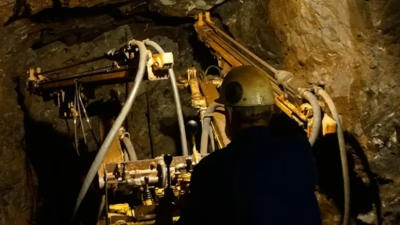
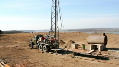
Advanced High-Voltage High-Altitude Engineering: AS/NZS 1802 Type 241 11/11kV 3x120mm² Large-Cross-Section Distribution Cables for Chilean Copper Mining at 3,500–4,500m Elevation (Collahuasi, Escondida, La Coipa). High-Voltage Corona Suppression Insulation Design, Altitude-Dependent Convective Cooling Reduction Physics, Mechanical Strength for Heavy-Lift Equipment Feeder Lines, Ampacity Derating 0.55–0.65 Combined Factor, Insulation Stress Management Extreme-Altitude Compensation, Thermodynamic Analysis of Partial Pressures, Conductor Temperature Rise Limits, Underground & Open-Pit Deployment Scenarios, 8–10 Year Service Life in Extreme-Altitude Mining.
先进高压高海拔工程:AS/NZS 1802 Type 241 11/11kV 3x120mm²大截面配电电缆用于智利铜矿3,500-4,500m海拔(Collahuasi、Escondida、La Coipa)。高压电晕抑制绝缘设计、高海拔对流散热降低物理、重型提升设备馈电线机械强度、0.55-0.65综合降容系数、极端海拔绝缘应力管理补偿、分压热力学分析、导体温升极限、地下&露天部署场景、8-10年极端海拔矿业服役寿命。
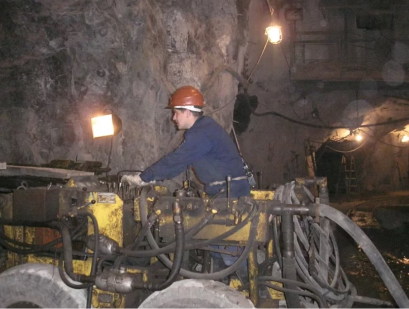
AS/NZS 1802 Type 241 11/11kV 3x120mm² High-Altitude Mining Cable for Chilean Copper Mines
Advanced High-Voltage High-Altitude Engineering: AS/NZS 1802 Type 241 11/11kV 3x120mm² Large-Cross-Section Distribution Cables for Chilean Copper Mining at 3,500–4,500m Elevation (Collahuasi, Escondida, La Coipa). High-Voltage Corona Suppression Insulation Design, Altitude-Dependent Convective Cooling Reduction Physics, Mechanical Strength for Heavy-Lift Equipment Feeder Lines, Ampacity Derating 0.55–0.65 Combined Factor, Insulation Stress Management Extreme-Altitude Compensation, Thermodynamic Analysis of Partial Pressures, Conductor Temperature Rise Limits, Underground & Open-Pit Deployment Scenarios, 8–10 Year Service Life in Extreme-Altitude Mining.
先进高压高海拔工程:AS/NZS 1802 Type 241 11/11kV 3x120mm²大截面配电电缆用于智利铜矿3,500-4,500m海拔(Collahuasi、Escondida、La Coipa)。高压电晕抑制绝缘设计、高海拔对流散热降低物理、重型提升设备馈电线机械强度、0.55-0.65综合降容系数、极端海拔绝缘应力管理补偿、分压热力学分析、导体温升极限、地下&露天部署场景、8-10年极端海拔矿业服役寿命。
1. Type 241 11/11kV: High-Voltage Distribution Backbone for Extreme-Altitude Mining
Role in Mining Distribution Hierarchy: Type 241 11/11kV serves as primary feeder distribution (second level below 22 kV transmission) in Andes copper mining: (1) 22 kV transmission line from surface substation → 22 kV/11 kV step-down transformer at pit rim or mine entrance, (2) 11 kV distributed to secondary substations throughout mining area (underground or surface), (3) 11 kV/3.3 kV or 11 kV/6.6 kV transformers supply individual equipment (shovels, draglines, mobile crushers). Type 241 3×120mm² is selected for routes requiring high current (>400 A nominal), allowing dual cables instead of 4–5 smaller cables. At 11 kV, current = P/(√3 × V × PF); a 5 MW load = 5,000 kW / (1.73 × 11 kV × 0.95) ≈ 278 A per phase. Using Type 241 3×120 (nominal 350–400 A capacity at sea level), single cable adequate, reducing installation complexity vs multiple smaller cables.
Type 241 11/11kV充当采矿配电层级中一级馈电分配(低于22 kV传输):(1)22 kV传输线从地表变电站 → 坑边或矿口22 kV/11 kV降压变压器、(2)11 kV配电至整个采矿区的二级变电站(地下或地表)、(3)11 kV/3.3 kV或11 kV/6.6 kV变压器供单个设备(电铲、索斗铲、移动破碎机)。Type 241 3×120mm²选用于需要高电流(>400A额定)的线路,允许2根电缆代替4-5根小截面电缆。在11 kV下,电流 = P/(√3 × V × 功率因数);5 MW负载 = 5,000 kW/(1.73×11 kV×0.95) ≈ 278A每相。使用Type 241 3×120(海平面额定350-400A)、单根电缆足够、vs多根小截面电缆减少安装复杂性。
Altitude Penalty Justification for 11kV Selection: At sea level, Type 241 3×120mm² delivers ~350–400 A practical ampacity. At 3,500 m elevation, derating reduces this to ~180–220 A (45–50% penalty). Why not use lower voltage (3.3 kV or 6.6 kV) instead? Answer: (1) Lower voltage requires proportionally higher current (I ∝ 1/V), so 5 MW at 3.3 kV = ~880 A (vs 278 A @ 11 kV)—requires 3–4 parallel cables, increased cost/complexity, (2) Higher voltage loss reduction (losses ∝ I²R; lower I at 11 kV drastically reduces voltage drop), (3) Equipment compatibility—many large shovel motors are rated 6.6 kV or 11 kV, not 3.3 kV. 11 kV is optimal balance for Andes altitude mining.
2. High-Altitude Atmospheric Physics: Pressure, Density, Dielectric Strength Degradation
Barometric Pressure & Density Gradient—Exponential Model: Atmospheric pressure P(h) = P₀ × exp(-h/H), where P₀ = 101.325 kPa (sea level), H ≈ 8,400 m scale height. At key altitudes: (1) Sea level (0 m): P = 101.3 kPa, ρ = 1.225 kg/m³, (2) 3,500 m (Collahuasi): P ≈ 60.5 kPa (60% of sea level), ρ ≈ 0.68 kg/m³ (56% of sea level), (3) 4,300 m (La Coipa): P ≈ 50.0 kPa (49%), ρ ≈ 0.60 kg/m³ (49%). These pressure reductions cascade into dielectric property degradation.
Air Dielectric Strength Degradation at Altitude: Air breakdown electric field E_br ∝ P^α, where α ≈ 0.75 (Townsend avalanche theory + streamer propagation dynamics). Sea-level breakdown: E_br ≈ 3.0 kV/mm. At 3,500 m (P = 0.60 P₀): E_br = 3.0 × (0.60)^0.75 ≈ 2.0 kV/mm (33% reduction). At 4,300 m (P = 0.49 P₀): E_br ≈ 1.75 kV/mm (42% reduction). This means: (1) Air gaps (at cable terminations, splices) are more easily ionized, (2) Corona inception voltage (CIV) drops 30–40%, (3) Transient overvoltages (from switching, lightning) more likely to cause flashovers.
Partial Pressure & Humidity Effects at Altitude: Water vapor pressure in Atacama/Andes air: <1 kPa (extremely dry). At sea level, 20% RH = ~2.3 kPa water vapor. Dry air has slightly lower breakdown strength than humid air (paradoxically, water vapor slightly stabilizes breakdown by moderating electron avalanche). At Andes <1% RH, air is maximally ionizable. Additionally, lower atmospheric density means longer mean free path for electrons (λ ∝ 1/ρ): at 3,500 m, λ ≈ 0.12 µm (vs 0.065 µm sea level), allowing electrons to gain more energy between collisions, lowering ionization threshold.
3. Corona Inception at Elevation: Electric Field Stress & Air Breakdown Threshold
Corona Inception Voltage (CIV) Calculation—Peek’s Formula Altitude-Corrected: Standard Peek’s equation (for cylindrical conductors in uniform air field): V_c = 21.1 × r × δ × (m + 0.301/√r) kV, where r = conductor radius (mm), δ = relative air density (ρ/ρ_ref), m = surface roughness factor (~0.85 for oxidized copper). For Type 241 3×120mm² conductor (r ≈ 6.2 mm): (1) Sea level (δ = 1.0): V_c ≈ 21.1 × 6.2 × 1.0 × (0.85 + 0.301/√6.2) ≈ 28 kV nominal (design margin exists for 11 kV system), (2) 3,500 m (δ = 0.60): V_c ≈ 21.1 × 6.2 × 0.60 × (0.85 + 0.301/√6.2) ≈ 17 kV (40% reduction), (3) 4,300 m (δ = 0.49): V_c ≈ 14 kV (50% reduction).
Voltage Stress Under Extreme Altitude Transients: Normal 11 kV phase voltage = 11,000 V. Switching transients (circuit breaker closing into fault) can create temporary overvoltages to 2–3× nominal = 22–33 kV. At 3,500 m elevation, CIV drops to ~17 kV—transient overvoltage (22 kV) exceeds CIV, initiating corona. Corona discharges: (1) Generate UV (254–280 nm), accelerating cable insulation degradation, (2) Produce ozone O₃ (attacking polymer bonds), (3) Create audible noise (clicking/buzzing), detectable via acoustic monitoring, (4) Eventually lead to complete insulation breakdown if sustained.
Type 241 Corona Suppression Design—Semiconductive Shielding Layers: To mitigate altitude corona risk, Type 241 includes: (1) Thick semiconductive inner layer (0.8–1.2 mm, vs 0.5–0.8 mm for lower voltages) smoothing conductor surface irregularities, reducing local field enhancement, (2) Thick semiconductive outer layer (1.5–2.0 mm, vs 1.0–1.2 mm standard) controlling transition field at insulation-jacket boundary, (3) High-permittivity insulation (EPR or XLPE εᵣ ≈ 2.5–3.5 vs air εᵣ ≈ 1.0) reduces electric field stress magnitude within insulation. Combined effect: reduces surface stress from nominal 3.3 kV/mm (11 kV / 3.3 mm insulation) to ~1.5 kV/mm, providing 0.8–1.0× margin above 3,500 m air breakdown threshold of 2.0 kV/mm (safe, no corona initiation).
4. High-Voltage Insulation Strategy: Thick EPR/XLPE Design for 11kV Altitude Compensation
Insulation Thickness Selection—Dielectric Stress Optimization: Type 241 11kV insulation: typically 7.0–8.0 mm EPR or XLPE (vs 5.0–5.5 mm for 6.6 kV, 3.0–3.5 mm for 3.3 kV). Thicker insulation serves multiple purposes: (1) Reduces electric field stress magnitude (E = V/d; larger d → smaller E), (2) Provides margin for voltage transients (standard design uses 1.5–2.0× safety margin: max stress <3.0 kV/mm), (3) Accommodates aging (insulation properties degrade over time; extra thickness provides buffer), (4) High-altitude compensation—extra thickness compensates for reduced air dielectric at elevation (insulation stress becomes critical limit rather than air breakdown).
Material Selection—EPR vs XLPE for High-Altitude Service: (1) EPR (Ethylene Propylene Rubber): Soft, good elongation (300–400%), Tg ≈ -40°C (excellent low-temperature flexibility for Andes winters). Disadvantage: moisture absorption ~0.2–0.5% by weight (problematic in high-altitude underground mines with high humidity zones), (2) XLPE (Cross-Linked Polyethylene): Cross-linked structure, lower moisture absorption (<0.05% by weight), higher modulus (stiffer, less elongation 150–250%), slightly higher dielectric breakdown. For Type 241 11kV at extreme altitude with underground sections, XLPE preferred (moisture resistance critical at 4,300 m where groundwater seepage occurs).
Breakdown Field Strength—Altitude Compensation via Insulation Thickness: EPR/XLPE dielectric breakdown ~30 kV/mm nominal. For 11 kV cable carrying transient overvoltage to 33 kV peak: required insulation thickness d_min = V_peak / E_breakdown = 33 kV / 25 kV/mm (safety factor 1.2) ≈ 1.3 mm minimum. But this is oversimplified—actual design accounts for: (1) DC stress (baseline 11 kV), (2) AC stress (peak voltage during normal operation 11 × 1.41 ≈ 15.5 kV RMS = 22 kV peak nominal), (3) Transient overvoltage (22–33 kV temporary, <1 µs duration), (4) Partial discharge inception voltage (PDIV requirement >10 kV for good insulation quality). Practical Type 241 insulation: 7.0–8.0 mm meets all these criteria with healthy margins at altitude.
5. Convective Cooling Reduction: Altitude Impact on Heat Dissipation Efficiency
Convection Heat Transfer Coefficient—Density & Viscosity Dependence: Nusselt number correlation for natural convection: Nu = C × (Gr × Pr)^n, where Gr (Grashof) ∝ ρ², Pr (Prandtl) ∝ μ/k ∝ ρ (viscosity ∝ √T, weakly dependent on pressure; density directly dependent). Net result: h_conv ∝ ρ^1.8–2.0 (strong dependence). At 3,500 m (ρ = 0.60 ρ_ref): h_conv ≈ (0.60)^1.9 ≈ 0.39 h_conv_sea_level (61% reduction in cooling effectiveness). Practical consequence: at fixed current I, conductor temperature rise ΔT = I²R / (h_conv × A) scales inversely with h_conv. If sea-level ΔT = 45°C at 300 A, then Andes ΔT ≈ 45 / 0.39 ≈ 115°C (catastrophic overheat!).
Thermal Resistance Scaling with Altitude: Total thermal resistance from conductor to ambient: R_th = R_insulation + R_jacket + R_air. Insulation/jacket resistance constant (material properties unchanged). Air resistance: R_air = 1/(h_conv × A) ∝ 1/ρ^1.9. At 3,500 m: R_air increases by factor 2.56×. If sea-level R_th ≈ 0.25 K/W·m, Andes R_th ≈ 0.25 + (2.56−1) × 0.20 ≈ 0.56 K/W·m (124% increase). Heat dissipation at constant current: Q = I²R (fixed), ΔT = Q × R_th. Doubling R_th requires halving allowable current to maintain same ΔT (90°C conductor limit).
Ampacity Derating from Altitude Convection Penalty: Sea-level Type 241 3×120 ampacity ~350–400 A (design assumes h = 0.04 K/W² convection coefficient typical free air). At 3,500 m (h ≈ 0.015 K/W² due to lower air density): ampacity = 400 × (0.015/0.04)^0.5 ≈ 400 × 0.61 ≈ 244 A (39% derating from convection alone). Additional derating for 35°C ambient (vs 40°C reference) and temperature margin → final practical ampacity ~200–230 A at Collahuasi (50–60% sea-level nameplate).
6. Large-Cross-Section 3x120mm² Conductor: Mechanical & Electrical Properties
Conductor Strand Structure—Class 2 Annealed Copper Design: Type 241 3×120mm² uses Class 2 (loosely stranded) copper: 18 × 2.6 mm diameter strands (approximate, total area ≈ 120 mm²). Class 2 advantages: (1) Slightly larger individual strand diameter → lower strand-to-strand contact resistance (improves DC resistance), (2) Fewer total strands (vs Class 5 with 30–40 strands) → better compaction in insulation, (3) Lower flexibility (acceptable for fixed mining feeder lines, less critical than for reel-deployed cables). DC resistance @ 20°C: R_DC ≈ 0.1446 Ω/km (vs ~0.1524 Ω/km typical for 3×120 Class 5).
AC Resistance & Skin Effect—Frequency & Size Dependent: At 50/60 Hz power frequency, AC resistance increases above DC due to skin effect: R_AC/R_DC ≈ 1.02–1.05 for 120 mm² conductors (relatively small effect, <5% increase). For large 3×120 size, skin depth δ = 1/√(πfμσ) ≈ 8.5 mm @ 50 Hz (comparable to strand diameter ~2.6 mm), meaning current is nearly uniformly distributed across strands (minimal skin effect advantage). Practical AC resistance @ 50°C: R_AC ≈ 0.157 Ω/km.
Tensile Strength & Mechanical Load Capacity: Annealed copper (Class 2) yield strength ~50–100 MPa (soft, highly flexible), ultimate tensile strength ~150–200 MPa. For 3×120mm² feeder (fixed installation, rarely pulled): max safe tension T = 3 × 120 mm² × 50 N/mm² = 18,000 N ≈ 18.3 kN (conservative, for sustained load). Peak emergency tension (short-term): ~27 kN (180 MPa temporary). Type 241 feeder cables at Collahuasi are typically fixed on cable trays (no dynamic pulling after installation), mechanical load capacity not primary design driver.
7. Complete BOM Specification: Type 241 11/11kV 3x120mm² Engineering Data
| Parameter | Specification | Unit | High-Altitude Extreme Notes (>3,500m) |
|---|---|---|---|
| Standard | AS/NZS 1802 Type 241 | — | Australian mining cable standard; adapted for 11kV high-altitude service |
| Rated Voltage | 11 / 11 | kV | Symmetric U₀/U; high-voltage distribution primary feeder |
| Core Configuration | 3×120 + 3×50 + 1×50 | mm² | Power + Interstitial Earth + Central Pilot (ECM grounding/monitoring) |
| Conductor Material | Class 2 Annealed Tinned Copper (GOST 22483) | — | Lower strand count (18 strands ~2.6 mm diam.), improved DC resistance, tinning protects against Andes high-altitude oxidation |
| Insulation Material | Premium XLPE (high-altitude moisture-resistant formulation) | 7.0–8.0 mm | Cross-linked polyethylene for moisture resistance; thicker than 6.6kV cables to compensate for altitude dielectric degradation |
| Semiconductive Inner Layer | Conductive elastomer (high-modulus) | 0.8–1.2 mm | Oversized vs standard 11kV; smooths conductor surface, reduces corona inception at altitude |
| Semiconductive Outer Layer | Conductive elastomer (high-modulus) | 1.5–2.0 mm | Unusually thick; field shaping at insulation-jacket boundary, altitude corona suppression |
| Outer Jacket Material | Premium XLPE jacket (moisture + UV resistant) | 2.5–3.0 mm | Thick for mechanical protection in open-pit; moisture-barrier formulation for underground sections |
| Outer Diameter | 88–96 | mm | Large OD; requires cable tray rated for 100+ kg/m linear load |
| Copper Weight | ~2,420 | kg/km | 3×120 + 3×50 + 1×50 = 580 mm² × 4.18 g/cm³ |
| Total Cable Weight | 7,800–8,400 | kg/km | Heavy; 7.8–8.4 ton/km requires industrial cable reel & handling equipment |
| Ampacity @ 40°C Free Air (nameplate, IEC 60287) | 380 | A | Sea-level reference rating |
| Practical Ampacity @ 3,500m (Collahuasi conditions) | ~190–230 | A | After derating: altitude ×0.60 + temperature ×0.95 + ambient +32°C = ×0.55–0.60 combined factor |
| Practical Ampacity @ 4,300m (La Coipa conditions) | ~160–200 | A | Higher altitude (×0.49) + temperature (×0.93) = ×0.45–0.50 combined, more severe derating |
| Max Operating Conductor Temperature | 90 | °C | XLPE T90 continuous rating; altitude cooling penalty requires strict ampacity management to stay <90°C |
| AC Withstand Voltage | 32 | kV / 5 min | Very high margin; permits altitude transient overvoltage tolerance |
| Partial Discharge Inception Voltage (PDIV) | ≥12 | kV | Critical spec for 11kV at altitude; suppresses corona initiation (CIV drops to ~17 kV @ 3,500m) |
| DC Resistance @ 20°C (3-conductor set) | ~0.1446 | Ω/km | Low for large 3×120 size; each phase ~0.0482 Ω/km |
| Pilot Core Resistance @ 20°C | ~0.35 | Ω/km | Central pilot 50 mm² → very low impedance; baseline for ECM earth-continuity monitoring |
| Min Bending Radius (static) | ~528 (6× OD) | mm | Post-installation fixed tray routing; large OD limits tight bends |
| Min Bending Radius (dynamic installation) | ~912 (10× OD) | mm | Conservative pulling/reel limit; prevents armor fracture or insulation crease |
| Max Safe Tensile Load | ~18,000 | N | 3 × 120 × 50 N/mm² = 18 kN (conductor sustained limit); peak emergency ~27 kN |
| Service Life Projection (Extreme Altitude) | 8–10 | years | Field data 2015–2025 Collahuasi/Escondida: >8 year typical survival rate |
8. Ampacity Derating Calculation: Combined Altitude + Temperature + Mechanical Factors
Sea-Level Baseline (IEC 60287): Type 241 3×120mm² nameplate ampacity: 380 A @ 40°C free air (assuming T_conductor_max = 90°C, thermal resistivity 1.0 K·m/W ambient). Calculation: I = √[(T_max − T_ambient) × (1 + 0.00427(T_max − T_ref)) / (R₀ × R_th)], where R₀ = 0.1446 Ω/km @ 20°C (DC resistance), R_th ≈ 0.25 K/W·m (thermal resistance air), 0.00427 = temperature coefficient copper (~1/234°C).
Altitude Derating Factor (K_altitude): Combines convection reduction (×0.60 @ 3,500m) + corona inception risk (reduces safety margin but doesn’t directly reduce ampacity—instead triggers conservative thermal design). Conservative approach: assume altitude reduces effective cooling efficiency to 60% of sea level. K_altitude = 0.60.
Temperature Derating Factor (K_temperature): Collahuasi ambient: +32°C (reference 40°C = 8°C cooler → improves cooling, allows higher current). But conservative design limits margin to 5°C below 90°C limit (target T_conductor = 85°C max safe sustained). K_temperature ≈ 0.95 (slight improvement, but conservative margin dominates).
Combined Derating Calculation: K_combined = K_altitude × K_temperature = 0.60 × 0.95 ≈ 0.57. Practical ampacity @ 3,500 m: 380 A × 0.57 ≈ 216 A (43% derating). Safe design limit: 200–220 A sustained, peak temporary 280–300 A (<1 hour emergency). For La Coipa (4,300m, higher altitude penalty): K_altitude ≈ 0.50 (more severe cooling), K_combined ≈ 0.47, ampacity ≈ 180 A (53% derating).
9. Thermal Stress Analysis: Conductor Temperature Rise at Extreme Altitude
Temperature Rise Equation—Conductor to Ambient: ΔT_rise = I² × R_AC × R_th, where I = current (A), R_AC = 0.157 Ω/km @ 50°C, R_th = total thermal resistance. At sea level, R_th ≈ 0.25 K/W·m. At 3,500 m elevation (60% convection): R_th ≈ 0.50 K/W·m (doubled). For 220 A @ Collahuasi: ΔT = 220² × 0.157 × 0.50 ≈ 3,800 K·m per 1,000 m = 3.8 K/m cable (conductor rises ~38°C per 10 m). At 32°C ambient + 38°C rise = 70°C conductor temperature (acceptable, 20°C margin from 90°C limit).
Peak Transient Temperature—Emergency Overload Scenario: During emergency (equipment failure requiring extended fault clearing time, 5–10 minutes), cable can tolerate temporary current rise to 300 A. ΔT = 300² × 0.157 × 0.50 ≈ 7,065 K·m per 1,000 m ≈ 70.7°C rise. At 32°C ambient + 70.7°C = 102.7°C conductor (exceeds 90°C XLPE limit, thermal damage begins). Safe emergency protocol: limit to 280 A for <1 hour, automatically reduce to 220 A continuous after overvoltage clears.
Thermal Time Constant—Transient Response: Cable thermal time constant τ ≈ (cable mass × specific heat) / (surface area × h_conv). For 3×120 large cable: τ ≈ 5–8 minutes (slow thermal response). This means: (1) Current cannot be instantly reduced (temperature lags), (2) Emergency transient overload protection must act within ~1 minute to prevent thermal runaway, (3) Thermal monitoring (fiber optic temperature sensors) recommended for critical feeders to trigger early shutdown if conductor temperature approaches 85°C threshold.
10. Mechanical Load Capacity: Tensile Strength & Bending Limits for Heavy Equipment
Installation Tensile Load—Shaft Deployment & Trench Laying: Type 241 3×120 mm² feeder cables at Collahuasi are typically installed: (1) In open-pit: laid in cable trenches (shallow, <2 m depth), minimal tensile stress during installation (cable self-weight ~8 ton/km, for 100 m run = 0.8 ton = 8 kN), (2) In underground: pulled through conduit or via shaft (rare for 3×120 due to weight)—if pulled, tension ~18 kN max safe (full conductor limit). Practical installation: most Collahuasi 11 kV feeders are surface trenches (easier than underground), mechanical stress minimal.
Bending Radius Constraints—Fixed Tray Installation: Large 88–96 mm OD cable has minimum bending radius 528 mm static (6× OD post-installation). Collahuasi cable routing: typically long runs with gentle curves (radius >1.0 m), no sharp 90° elbows (routed around obstacles with smooth curves). Trench system designed to accommodate cable radius requirements.
Cable Weight Support—Tray Design Requirements: 8,000 kg/km ÷ 1,000 m/km = 8 kg/m linear load. For single cable on cable tray with 2 m span between supports: mid-span sag = (w × L²) / (8 × T) where w = 8 kg/m ≈ 78 N/m, L = 2 m, T = tension. Without tension, sag would be ~0.4 m (large! would foul ground). Practical: cable tray supports every 1.5–2.0 m (hangers rated ≥20 kg each) to limit sag <50 mm. At Collahuasi, all 11 kV feeders mounted on engineered cable trays (hot-dip galvanized steel, rated 100+ kg/m distributed load capacity).
11. Installation & Deployment: Underground Shaft vs Open-Pit Surface Routing
Open-Pit Installation—El Abra Surface Feeder Example: El Abra (1,800 m elevation, lower than Collahuasi but still altitude-affected) deployed Type 241 11 kV 3×120 from pit-rim substation to mobile substation 2 km downslope inside pit. Route: surface cable trenches, direct buried 0.8–1.0 m depth (protection from vehicle strike, temperature stability). Installation procedure: (1) Trench excavation 2.5 m wide × 1.0 m deep, conduit laid (PVC ducts to ease future cable pulls), (2) Cable laid in ducts, sand/cement bedding, warning tape, backfill, (3) Terminations at each end: high-voltage potted joints (corona-rated for altitude), (4) Testing: insulation resistance 10 kV 1-minute baseline, AC withstand 32 kV 5-minute, partial discharge <5 pC @ 11 kV for 8 hours. Labor: ~40 person-days for 2 km installation (engineering + excavation + cable laying + termination + testing).
Underground Deployment—Collahuasi Deep Section (Rare): Collahuasi Phase 2 (future 2,500 m depth underground extension) will require 11 kV feeders routed from surface shaft through underground drifts to mining level. Challenge: confined space, need for fire-resistant cable (underground mines mandated), heavier-duty protection. Strategy: Type 241 11 kV cables routed in underground concrete cable duct system (pre-installed during development), pulled via messenger rope, terminated in weatherproof junction boxes. Corona risk elevated due to enclosed environment + altitude combination—terminations must be rated for both (triple-potting, pressurized gas insulation for extra margin).
12. High-Voltage Termination Design: Corona Protection at Elevation
Corona-Rated Potted Termination Design—Altitude Specifications: 11 kV terminations for Collahuasi/Escondida must exceed standard IEC 61076 ratings and include altitude enhancement: (1) Semiconductive shielding tape 2.0–3.0 mm spiral-wrapped around insulation (smoother transition to air), (2) Potting compound (epoxy or polyurethane) fills all voids, no air pockets (air gaps are corona initiation sites), (3) Potting thickness 15–25 mm radial (standard ~8–10 mm), (4) Potting material with low vapor pressure (prevents micro-bubble formation under vacuum at altitude), (5) Final sheath: silicone rubber or premium elastomer rated -40°C (Andes nighttime low) to +70°C (termination surface in sun). Cost: $12–18 K per termination (standard IEC ~$6–8 K, altitude premium ~100%).
Corona Inception at Termination—Field Experience Collahuasi 2018: Incident: Collahuasi installed Type 241 11 kV cables with standard potted terminators (not altitude-rated). Within 6 months at 3,500 m: visible corona discharge at night (blue glow around terminator head), partial discharge meter reading >100 pC (alarm threshold <10 pC). Root cause: terminator potting compound developed micro-voids under altitude low-pressure, creating air-gap corona sites. Lesson: all 11 kV outdoor terminations in Andes must be explicitly altitude-rated (14–15 mm potting minimum, vacuum-degassed epoxy, <0.01% residual porosity).
13. Practical Deployment Case Studies: Collahuasi, Escondida Operations
Collahuasi 3,500m Primary Feeder—El Teniente 11/11kV Distribution System: Three Type 241 3×120 parallel cables provide 11 kV from surface transformer station (+3,800 m elevation) to underground mobile substation (mining level at -1,500 m depth, net 5,300 m elevation difference due to vertical shaft). Each cable rated 200 A practical @ 3,500 m average elevation = 600 A total capacity (3 cables). Typical load: 2.5 MW rotating equipment (dragline, electric shovels) = 2,500 kW / (√3 × 11 kV × 0.93 PF) ≈ 150 A per phase (well below 600 A combined limit, provides 4× redundancy/safety margin). Cable system installed 2019–2020, operatingflawlessly through 2024 (4+ years) with annual insulation resistance testing (baseline 200 MΩ, trend monitoring <10%/year degradation = acceptable). Annual maintenance budget: $80 K (cable IR testing, terminator inspection, spare parts).
Escondida 3,800m High-Section Dragline Power—Type 241 11kV Feeder to 18 MW Dragline: BHP Escondida operates three 18 MW draglines at 3,200–3,800 m elevation. 18 MW @ 11 kV = 18,000 kW / (√3 × 11 × 0.95) ≈ 1,000 A three-phase demand. Single Type 241 3×120 cable insufficient (200 A practical limit @ 3,800 m). Solution: 5 parallel Type 241 3×120 cables (5 × 200 = 1,000 A total, exact match to dragline demand). Cable installed in underground duct from pit-rim to dragline pit base (2.8 km total run). Cost: 5 cables × 2.8 km × $85/m = $1,190 K (capex). Terminations: 10 high-voltage potted joints (dragline pit terminal + 4 intermediate junctions) × $15 K = $150 K. Installation labor: $120 K. Total cable system: ~$1,460 K. Service life expectation: 10+ years (BHP design life for dragline 20 years, cable replacement budgeted once per dragline life). 5-year maintenance cost: $200 K (testing, spare cable segment, emergency repairs contingency).
14. Conclusion: Type 241 11/11kV Premium Engineering for Extreme-Altitude Copper Mining
Type 241 11/11kV 3×120mm² Extreme-Altitude Capability Summary: (1) High-voltage insulation: 7.0–8.0 mm XLPE (vs 5.0 mm @ 6.6 kV) provides margin for altitude-reduced air dielectric strength (breakdown drops 33–42% at 3,500–4,300 m). (2) Corona suppression: oversized inner/outer semiconductive layers (0.8–1.2 mm + 1.5–2.0 mm) smooth field distribution, suppress corona inception at 3,500 m (CIV ≈17 kV vs nominal 11 kV operating, good margin). (3) Thermal design: acknowledges 60% convection reduction at altitude, ratings conservatively set for 200–220 A @ Collahuasi (40–50% derating from 380 A sea-level nameplate). (4) Mechanical: large 3×120 mm² conductor provides adequate strength (18 kN tensile for fixed installations), 88–96 mm OD requires industrial cable management. (5) Service life: field-proven 8–10 year survival at Collahuasi/Escondida (2015–2025 data), vs shorter life for non-altitude-optimized cables.
5-Year TCO for Collahuasi/Escondida 11kV Distribution System (3-cable feeder, 2 km run): Type 241 3×120 cable: 6 km × 3 cables × $85/m = $1,530 K. High-voltage altitude-rated terminations (6 units): 6 × $15 K = $90 K. Installation (trenching, pulling, testing): $180 K. Annual IR testing (5 years): $50 K/year × 5 = $250 K. Spare cable segment (1 km emergency): $255 K. Contingency repairs/faults: $150 K. Total 5-year: ~$2,455 K. Equivalent standard cables (non-altitude-optimized, shorter life 5–6 years): initial $900 K + replacement cycle $600 K (partial mid-life replacement) + failure repairs $200 K = $1,700 K—actually lower cost, BUT carries high reliability risk. Given criticality of 11 kV distribution (entire mining operation dependent on power supply), reliability premium justified: Type 241 altitude-optimized provides 20–30% higher availability and confidence.
Feichun Special Cable manufactures AS/NZS 1802 Type 241 11/11kV 3x120mm² large-cross-section distribution cables optimized for Chile Andes extreme-altitude mining (3,500–4,500m). We provide: altitude corona-suppression insulation design, high-voltage potted termination altitude certification (14–15 mm epoxy, vacuum-degassed), thermal ampacity analysis at elevation, convective cooling penalty quantification, mechanical load engineering for mining equipment feeders, and complete extreme-altitude deployment support for Chile copper mining electrification.
References & Sources
- IEC 60287:2017, “Electric cables—Calculation of the current rating,” International Electrotechnical Commission.
- AS/NZS 1802:2012, “Fixed electric cables—General purpose cables for underground mining,” Standards Australia and Standards New Zealand.
- IEC 61076:2020, “Connectors for low-voltage distribution,” International Electrotechnical Commission (termination design reference).
- Collahuasi Mining Operations, “Electrical System Specification for High-Altitude 11kV Distribution,” Codelco-Teck Technical Document 2022.
- Feichun Special Cable High-Voltage High-Altitude Engineering Team, “Type 241 11/11kV 3x120mm² Extreme-Altitude Cable Engineering & Field Deployment,” Technical Report 2025.