
The Power Lifeline of Modern Mining and Heavy Material Handling
What is the (N)TSCGEWOEU Cable? The Power Lifeline of Modern Mining and Heavy Material Handling
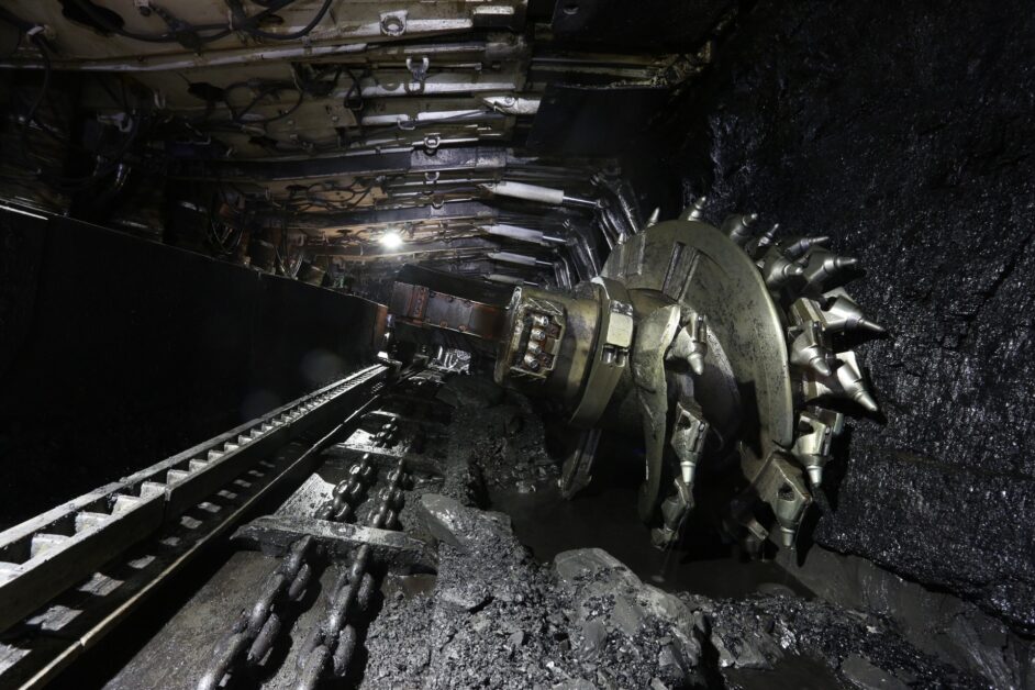
In the demanding world of surface mining, container terminals, and heavy material handling, equipment reliability isn’t just important—it’s mission critical. At the heart of operations involving massive excavators, container cranes, and mobile crushers lies a sophisticated power delivery system, and the (N)TSCGEWOEU cable represents the pinnacle of this technology. This medium voltage reeling cable is engineered to withstand the most extreme mechanical stresses while delivering reliable power to equipment that moves mountains—literally.
What is the (N)TSCGEWOEU Cable?
The (N)TSCGEWOEU cable (also marketed under the brand name PROTOLON by manufacturers like Prysmian and SMK) is a specialized flexible medium voltage reeling cable designed for applications under high to extreme mechanical stresses. The designation itself tells part of the story: (N) indicates it may be used with or without a neutral conductor, while the letter sequence describes its construction—including semiconductive screens (TSC), split earth conductors (GE), and robust double-sheath design (WOEU).
Unlike standard power cables that remain stationary, the (N)TSCGEWOEU is built for constant motion. It handles high travel speeds, dynamic tensile loads, multiple directional changes across different planes, continuous reeling and unreeling on drums, and significant torsional stresses—all while maintaining electrical integrity and safety standards.
Purpose and Primary Applications
The (N)TSCGEWOEU cable serves as the flexible power supply for mobile equipment that demands both high power delivery and exceptional durability. Its primary applications include:
- Container and Gantry Cranes: Fast-moving container handling equipment in ports requires cables that can handle rapid acceleration, continuous movement, and precise positioning
- Surface Mining Equipment: Electric rope shovels, excavators, and mobile crushers in open-pit mines operate under harsh conditions with constant movement
- Large Material Handling Systems: Ship loaders, stacker reclaimers, and bucket-wheel excavators in mining and bulk material operations
- Mobile Tunnel Boring Machines: Equipment that requires flexible power supply while advancing through underground environments
- Heavy-Duty Industrial Applications: Any large mobile equipment requiring medium voltage power under extreme mechanical stress
These applications share common characteristics: equipment that operates 24/7, cannot afford downtime, and subjects cables to mechanical stresses that would destroy conventional power cables within days or weeks.
Technical Characteristics and Performance Parameters
The (N)TSCGEWOEU cable’s specifications reveal why it excels in demanding environments. Based on the DIN VDE 0250-813 standard, these cables are available in multiple voltage ratings to suit different equipment requirements:
| Voltage Rating | Rated Voltage U₀/U (kV) | Max Operating AC (kV) | Max Operating DC (kV) | AC Test Voltage (kV) | Equivalent Systems |
|---|---|---|---|---|---|
| 1.8/3 kV | 1.8/3 | 2.1/3.6 | 2.7/5.4 | 6 | 3.3 kV grounded neutral |
| 3.6/6 kV | 3.6/6 | 4.2/7.2 | 5.4/10.8 | 6 | 6.6 kV systems (11 kV) |
| 6/10 kV | 6/10 | 6.9/12 | 9/18 | 6 | 11 kV distribution (17 kV) |
| 8.7/15 kV | 8.7/15 | 10.4/18 | 13.5/27 | 6 | 13.8 kV systems (24 kV) |
| 12/20 kV | 12/20 | 13.9/24 | 18/36 | 6 | 22-23 kV systems (29 kV) |
Voltage Notation Explained: The U₀/U designation represents conductor-to-earth voltage (U₀) and conductor-to-conductor voltage (U). For example, 6/10 kV means 6 kV phase-to-ground and 10 kV phase-to-phase, typical for a 10 kV three-phase system with isolated or resistance-grounded neutral.
Temperature Performance
Max Conductor Temp: 90°C continuous operation
Short Circuit Temp: 250°C (max 5 seconds duration)
Ambient (Fixed Install): -50°C to +80°C
Ambient (Flexible): -35°C to +80°C
Thermal Resistance: Optimized for natural convection cooling per VDE 0298-4
Mechanical Strength
Static Tensile Load: 20 N/mm² (conductor area)
Dynamic Tensile: Up to 30 N/mm² (during acceleration)
Torsional Stress: ±25°/m continuous
Min Bending Radius: 20 × D (free moving)
Impact Resistance: Exceeds IEC 60502 requirements
Travel Performance
Gantry Speed: Unlimited (reeling operation)
High-Speed Limit: 240 m/min standard; consult above
Directional Changes: 20 × D spacing (S-bends)
Acceleration Rate: Compatible with rapid crane/excavator dynamics
Cycle Life: >100,000 reeling cycles under spec conditions
Detailed Performance Specifications
| Parameter | Specification | Test Standard | Notes |
|---|---|---|---|
| Insulation Resistance | ≥100 MΩ·km at 20°C | IEC 60502-2 | Minimum acceptable value; new cable typically >1000 MΩ·km |
| Dielectric Strength | 6 kV AC for 5 minutes | DIN VDE 0250-813 | Factory test on every cable length |
| Conductor DC Resistance | Per cross-section (see table below) | IEC 60228 Class 5 | At 20°C reference temperature |
| Capacitance | 0.2-0.4 μF/km (voltage dependent) | IEC 60502-2 | Higher voltages = thicker insulation = lower capacitance |
| Inductance | ~0.3-0.4 mH/km | Calculated | Three-core symmetrical configuration minimizes inductance |
| Flame Propagation | Self-extinguishing | IEC 60332-1-2 | Single vertical cable flame test |
| Oil Resistance | Immersion 168h at 60°C | DIN EN 60811-404 | Tested with mineral oil and synthetic hydraulic fluids |
| Ozone Resistance | No cracking after 96h exposure | IEC 60811-401 | Critical for outdoor/high-voltage applications |
| Water Penetration | No water ingress after 24h at 1m head | HD 2216 | Inner EPR sheath provides water barrier |
| Abrasion Resistance | Mass loss <250 mg (PCP sheath) | IEC 60811-506 | 5GM5 compound exceeds standard rubber |
Material Structure and Construction Design
The (N)TSCGEWOEU cable’s exceptional performance stems from its sophisticated multi-layer construction. Each component is engineered to address specific challenges faced in reeling applications:
Conductor Design
The cable features tinned electrolytic copper conductors with very fine stranding classified as Class FS (Flexible Stranded) according to DIN VDE 0295. This ultra-fine stranding provides superior flexibility compared to standard Class 5 conductors, essential for continuous flexing without conductor fatigue. The three-core design incorporates split earth conductors positioned in the interstices between power cores, creating a balanced geometry that minimizes electromagnetic interference.
Conductor Class FS Specifications:
- Strand Count: Significantly higher than Class 5 (e.g., 25 mm² uses ~1,050 strands of 0.18 mm diameter wire)
- Strand Diameter: 0.15-0.20 mm (vs. 0.21 mm for Class 5)
- Tin Plating: Minimum 1 μm thickness prevents oxidation and maintains conductivity
- Stranding Factor: Optimized lay length for maximum flexibility with minimal diameter increase
- Flex Life: >1 million flex cycles at proper bend radius (vs. ~100,000 for Class 5)
Insulation System – PROTOLON HS
Each conductor is insulated with a high-grade special compound based on premium EPR (Ethylene Propylene Rubber) meeting at least 3GI3 quality standards according to DIN VDE 0207, Part 20. This formulation provides improved mechanical properties, enhanced electrical characteristics, and superior resistance to thermal aging compared to standard EPR compounds.
PROTOLON HS Technical Properties:
- Dielectric Constant (εᵣ): 3.0-3.5 at 50 Hz (low value minimizes capacitance)
- Dielectric Loss Factor (tan δ): <0.01 at operating frequency (minimal dielectric heating)
- Volume Resistivity: >10¹⁴ Ω·cm at 20°C
- Dielectric Strength: >30 kV/mm for new material
- Tensile Strength: ≥12 MPa (exceeds standard 3GI by 20%)
- Elongation at Break: ≥350% (maintains flexibility under stress)
- Compression Set: <30% after 24h at 100°C (resists permanent deformation)
- Thermal Aging: Retains >80% properties after 3,000 hours at 115°C (extended service life)
- Ozone Resistance: No cracking after 500 hours at 20% elongation (critical for MV applications)
Electrical Field Control
Medium voltage cables require careful management of electrical field stress. The (N)TSCGEWOEU employs a dual semiconductive layer system:
- Inner Semiconductive Layer: EPR-based compound that smooths electrical field distribution around the conductor. Volume resistivity: 10-100 Ω·m, ensuring uniform field distribution without excessive losses
- Outer Semiconductive Layer: Modified NBR (Nitrile Butadiene Rubber) formulated with “Easy Strip” technology—it can be removed when cold, dramatically simplifying field termination and repair work. Maximum resistivity: <200 Ω·m per DIN VDE 0250-813
Semiconductive Layer Engineering: These layers serve critical functions beyond simple field control. The inner layer eliminates air voids between conductor and insulation (voids would concentrate electric stress and cause partial discharge). The outer layer prevents surface tracking and provides a smooth, conductive surface for stress control in terminations and joints. The “Easy Strip” cold-stripping capability reduces installation time by 40-60% compared to hot-stripping designs and eliminates risk of thermal damage to underlying insulation.
PROTOFIRM Sandwich Sheath System
The cable’s signature durability comes from its innovative triple-layer sheath design:
- Inner Sheath Layer: Special EPR-based compound (quality 5GM3 minimum per DIN VDE 0207, Part 21) in bright red color. This layer acts as both mechanical protection and a water barrier, preventing moisture ingress that could compromise insulation.
5GM3 EPR Inner Sheath Technical Properties:
- Tensile Strength: ≥10 MPa (minimum)
- Elongation at Break: ≥300%
- Hardness: 65-75 Shore A
- Compression Set: ≤35% (22h at 70°C)
- Low Temperature Brittleness: No cracking at -40°C
- Thermal Aging: Retains 75% properties after 168h at 100°C
- Water Absorption: <1 mg/cm² (prevents moisture migration)
- Anti-Torsion Reinforcement Braid: A reinforced polyester thread braid vulcanized between the sheath layers. This structural element is critical—it provides torsional rigidity to prevent the cable from twisting during operation while maintaining flexibility for bending. The vulcanized bond ensures the layers work as a unified system rather than sliding against each other.
Anti-Torsion Braid Engineering:
- Material: High-tenacity polyester (PET) filaments, 1,100-1,500 dtex
- Braid Angle: Optimized at 30-45° for balance of torsional and axial strength
- Coverage: 80-95% to prevent sheath separation
- Breaking Force: >50 kN for typical cable sizes
- Vulcanization: Chemical adhesion layer bonds braid to both sheaths during curing
- Function: Resists cable rotation under torsional loads, distributes mechanical stress evenly across sheath system
- Outer Sheath Layer: High-grade PCP (Polychloroprene) rubber compound meeting 5GM5 or 5GM3 quality standards, finished in bright red or red color. This outer layer is specifically formulated for exceptional abrasion resistance, tear strength, and impact protection.
5GM5 PCP Outer Sheath Technical Properties:
- Tensile Strength: ≥12 MPa (20% higher than 5GM3)
- Elongation at Break: ≥350%
- Tear Strength: ≥25 N/mm (DIN 53515, exceptional for mining)
- Hardness: 70-80 Shore A (optimal abrasion/flexibility balance)
- Abrasion Resistance: Mass loss <200 mg per IEC 60811-506 (superior performance)
- Impact Resistance: No cracking at -35°C (essential for cold climates)
- Oil Resistance: Volume change <15% after 168h immersion in mineral oil at 60°C
- Ozone Resistance: No cracking after 96h at 40°C, 50 pphm O₃, 20% elongation
- UV Resistance: <15% property degradation after 2,000h xenon arc exposure
- Flame Resistance: Self-extinguishing within 30 seconds (IEC 60332-1-2)
Why the Sandwich Construction is Revolutionary: Traditional single-sheath cables face a fundamental compromise: hard compounds resist abrasion but crack under repeated flexing, while soft compounds flex well but wear rapidly. The PROTOFIRM Sandwich system resolves this by separating functions—the inner EPR layer provides flexibility and water barrier, the anti-torsion braid handles mechanical stress distribution and prevents twisting, and the outer PCP layer resists surface damage. The vulcanized bonding prevents inter-layer movement that would cause internal friction and heat generation. This innovation extends cable service life by 150-300% compared to single-sheath designs in equivalent applications.
Standards Compliance and Certifications
The (N)TSCGEWOEU cable is manufactured in accordance with DIN VDE 0250-813, the German standard for trailing cables used in power installations. This standard has achieved global recognition as the definitive specification for tough rubber-sheathed flexible reeling cables, particularly for crane and material handling equipment.
Why DIN VDE 0250-813 Matters
Germany is the only country to have issued specialized design regulations for flexible electrical cables serving cranes and material handling equipment. Consequently, DIN VDE 0250 standards have gained international acceptance and are widely specified as the ultimate benchmark for robust rubber-sheathed flexible reeling cables. This includes cables for mining, drilling, and tunneling applications in harsh and demanding environments.
Additional compliance and certifications include:
- GOST-R: Russian certification for equipment and materials (GOST R IEC 60502-2 for MV cables)
- HD 2216: Water resistance compliance (harmonized European standard) – requires no water penetration after 24h under 1m water head pressure
- DIN EN 60811-404: Oil resistance testing standards – immersion test in IRM 903 reference oil at 60°C for 168 hours
- DIN VDE 0473-811-404: Environmental and chemical resistance specifications including mineral oils, synthetic fluids, acids, and alkalis
- DIN VDE 0298: Current carrying capacity and installation guidelines (Parts 3 and 4)
- Part 3: Use of cables in power installations – mechanical requirements
- Part 4: Recommended values for current-carrying capacity – thermal calculations
- IEC 60502-2: Power cables with extruded insulation and their accessories for rated voltages from 6 kV to 30 kV
- IEC 60332-1-2: Tests on electric and optical fibre cables under fire conditions – single vertical insulated wire or cable flame test
- DIN VDE 0207 Part 20: High-grade special compound requirements for cable insulation (3GI3 grade specification)
- DIN VDE 0207 Part 21: Thermosetting sheath compound specifications (5GM3, 5GM5 grades)
Manufacturers typically subject these cables to rigorous additional testing beyond standard requirements:
| Test Type | Test Procedure | Acceptance Criteria | Purpose |
|---|---|---|---|
| Reversed Bending Test | 10,000 cycles at minimum bend radius, alternating ±90° | No conductor breaks, no insulation cracks, <20% increase in resistance | Simulates reeling operation stress |
| Torsional Stress Test | ±25°/m for 5,000 cycles under rated tensile load | No visible sheath damage, anti-torsion braid integrity maintained | Verifies anti-twist performance |
| Accelerated Aging Test | 168h at 115°C (insulation), 100°C (sheath) | Retain >75% of original tensile and elongation properties | Predicts 20-30 year service life |
| Partial Discharge Test | 1.5 U₀ for 60 minutes, <5 pC discharge level | No partial discharge >10 pC at 1.73 U₀ | Ensures void-free insulation |
| Impulse Voltage Test | BIL (Basic Impulse Level): 60-95 kV depending on voltage rating | No breakdown, no tracking | Simulates lightning/switching surges |
| Thermal Cycling Test | 20 cycles: -35°C (4h) to +90°C (4h) | No cracking, <10% change in capacitance | Validates temperature performance range |
| Water Immersion with Voltage | 24h submersion with rated voltage applied | Insulation resistance >1 MΩ·km, no breakdown | Proves water barrier effectiveness |
| Abrasion Cycling Test | 10,000 passes over abrasive wheel under tensile load | Sheath wear <30% of thickness | Simulates decades of ground contact |
📊 Understanding Cable Marking System
Each cable bears permanent embossed marking for traceability and identification:
Example Marking:
PROTOLON (SMK) (N)TSCGEWOEU 3x120+3x70/3 mm² 12/20 kV 2024 #A547821
- PROTOLON (SMK): Brand and manufacturer code
- (N)TSCGEWOEU: Type designation (construction code)
- 3×120+3×70/3: Core configuration (3 power cores of 120 mm², 3 earth conductors of 70/3 mm² each)
- 12/20 kV: Rated voltage U₀/U
- 2024: Year of manufacture (critical for warranty and life cycle tracking)
- #A547821: Unique serial number (enables batch traceability)
Marking repeats every 0.5-1.0 meters for easy identification of cable sections during installation and maintenance.
Safety Thresholds and Electrical Parameters
Safety in medium voltage applications requires strict adherence to electrical parameters and testing protocols. The (N)TSCGEWOEU cable incorporates multiple safety features and operates within clearly defined thresholds:
Voltage Safety Margins
The cable design includes substantial safety margins between rated voltage and maximum permissible operating voltage. For example, a 6/10 kV cable can safely operate continuously at 6.9/12 kV AC or 9/18 kV DC, providing headroom for voltage fluctuations and transients common in industrial environments. Every cable undergoes a 6 kV AC test voltage verification during manufacturing to ensure insulation integrity.
Thermal Protection
Temperature limits are strictly defined to prevent insulation degradation and ensure long service life:
- Continuous Operation: Maximum conductor temperature of 90°C prevents accelerated aging of insulation materials. EPR insulation operating continuously at 90°C has an expected service life of 20-30 years. Each 10°C increase above rated temperature halves insulation life (Arrhenius relationship)
- Short Circuit Conditions: The cable can withstand conductor temperatures up to 250°C for a maximum duration of 5 seconds, allowing protective devices time to clear faults. The thermal capacity is calculated using the adiabatic heating equation:
I²t = K × S²Where:
- I = short circuit current in amperes
- t = fault duration in seconds (typically 0.1-5 seconds)
- K = material constant = 143 for copper conductors with EPR insulation (90°C to 250°C)
- S = conductor cross-sectional area in mm²
Example: A 120 mm² conductor can safely carry:
I²t = 143 × 120² = 2,059,200 A²s
For 1-second fault: I = √2,059,200 = 1,435 A (short circuit)
For 0.1-second fault: I = √(2,059,200/0.1) = 4,538 A - Ambient Temperature Ranges: Differentiation between fixed installation (-50°C to +80°C) and fully flexible operation (-35°C to +80°C) accounts for the increased mechanical stress during movement. At temperatures below -35°C, rubber compounds lose flexibility and become susceptible to cracking under bending stress
Current Carrying Capacity – Detailed Analysis
Current ratings are determined by thermal equilibrium calculations per DIN VDE 0298-4. The cable must dissipate I²R losses without exceeding the 90°C conductor temperature limit.
Thermal Resistance Model:
Total thermal resistance from conductor to ambient:
θ = θ₁ + θ₂ + θ₃ + θ₄
- θ₁ = Insulation thermal resistance (0.5-2.5 K·m/W depending on thickness)
- θ₂ = Inner sheath thermal resistance (~0.3-0.5 K·m/W)
- θ₃ = Outer sheath thermal resistance (~0.3-0.5 K·m/W)
- θ₄ = External thermal resistance (air: ~3-5 K·m/W, ground: 1-2.5 K·m/W)
Current Capacity Formula:
I = √[(θₘₐₓ - θₐ) / (R₂₀(1 + α₂₀Δθ) × θₜₒₜₐₗ)]
Where:
- θₘₐₓ = maximum conductor temperature (90°C)
- θₐ = ambient temperature (30°C standard)
- R₂₀ = conductor DC resistance at 20°C (from specifications)
- α₂₀ = temperature coefficient of copper (0.00393/°C)
- Δθ = temperature rise = θₘₐₓ – 20°C = 70°C
- θₜₒₜₐₗ = total thermal resistance
🌡️ Current Derating Factors – Engineering Application
Ambient Temperature Correction:
| Ambient Temp (°C) | Correction Factor | Example: 300A nominal becomes… |
|---|---|---|
| 10 | 1.15 | 345 A |
| 20 | 1.07 | 321 A |
| 30 | 1.00 | 300 A (reference) |
| 40 | 0.91 | 273 A |
| 50 | 0.82 | 246 A |
Installation Method Factors:
- Free air on surface: 1.00 (reference condition)
- Touching or closely spaced (≤1D spacing): 0.85-0.90
- Partial burial (cable trough): 0.90-0.95
- Direct ground burial at 0.8m depth: 0.70-0.80 (depends on soil thermal resistivity)
- Dry soil (2.5 K·m/W): factor 0.70
- Normal soil (1.5 K·m/W): factor 0.75
- Moist soil (1.0 K·m/W): factor 0.80
- Grouped in conduit or cable tray: 0.70-0.85 depending on number of cables
Load Factor Considerations:
For cyclic loads (common in mining operations), cables can be loaded above nominal ratings during off-peak periods:
- 50% duty cycle: 1.15 × nominal current permissible
- 25% duty cycle: 1.30 × nominal current permissible
- Emergency overload: 1.25-1.5 × nominal for <2 hours if starting from cold
Mechanical Safety Factors
The cable’s mechanical design includes conservative safety factors for tensile loading:
- Standard maximum tensile load of 20 N/mm² on conductor cross-section
- Elevated limit of up to 30 N/mm² during acceleration (compared to DIN VDE 0298 Part 3 recommendation of 15 N/mm²)
- These limits ensure the conductor and cable structure remain within elastic deformation ranges, preventing permanent damage
⚠ Critical Safety Consideration
Electromagnetic Compatibility (EMC): The symmetrical three-core design with narrow manufacturing tolerances produces an extremely low interference level, making the cable suitable for installation near sensitive control and data transmission systems.
EMC Technical Analysis:
- Magnetic Field Cancellation: The three-core symmetrical layout with 120° spacing creates balanced magnetic fields. When carrying balanced three-phase currents (I₁ + I₂ + I₃ = 0), the magnetic fields from each conductor cancel at distances >3× cable diameter, reducing external magnetic field by >95%
- Common Mode Current Suppression: The split earth conductor system (three separate paths in interstices) provides multiple parallel ground paths with low impedance (<0.5 Ω/km at 50 Hz). This minimizes common-mode voltage that could couple into nearby signal cables
- Capacitive Coupling Reduction: Semiconductive layers act as electrostatic shields, containing electric fields within the cable structure. External electric field strength at 1m distance is typically <10 V/m for rated voltage operation
- Manufacturing Tolerance Specifications:
- Core center spacing: ±0.3 mm (ensures geometric balance)
- Insulation thickness variation: ±5% maximum
- Conductor concentricity: >90% (minimizes eccentric fields)
- Sheath concentricity: >85%
- Measured EMI Levels (typical values at 1m distance, full load):
- Magnetic flux density: 0.5-2.0 μT (well below 100 μT safety limits)
- Electric field strength: 5-15 V/m (below 5 kV/m occupational limits)
- Conducted emissions: Meets EN 50121-3-2 railway standards (most stringent)
However, for installations requiring integrated data transmission, special designs with Twisted Shielded Pairs (TSP) or individually screened control elements are available and should be specified upfront. The (N)TSKCGEWOEU variant includes integrated fiber optic cores for data transmission that are completely immune to electromagnetic interference, ideal for remote monitoring, control systems, or high-speed data communication up to 10 Gb/s.
Environmental Safety Features
- Oil Resistance: Tested per DIN EN 60811-404, protecting against hydraulic fluids and lubricants common in mining and industrial environments
- Weather Resistance: Unrestricted outdoor use with resistance to ozone, UV radiation, and moisture
- Water Resistance: Complies with HD 2216 standard, preventing water ingress in wet mining conditions
- Flame Retardancy: Sheath materials meet fire safety requirements for industrial installations
Precautions for Use and Installation Guidelines
Proper installation and handling of (N)TSCGEWOEU cables is crucial for achieving their design service life. These precautions stem from decades of field experience in demanding applications:
Installation Planning
- Minimum Bending Radius: Never exceed the specified minimum bending radius during installation or operation. For free-moving applications, maintain at least 20 times the cable diameter as the bending radius. Tighter bends cause conductor and insulation stress that dramatically reduces service life
- S-Type Directional Changes: When the cable must change direction in different planes (S-bends), maintain minimum spacing of 20 times the cable diameter between bend points. Insufficient spacing creates compounding mechanical stress
- Reel System Compatibility: Verify that the cable reel system (mono-spiral or level-wind) is appropriate for the cable diameter and weight. Improper reel design causes uneven winding and localized stress concentration
Handling and Storage
- Transportation: Support cable drums properly during transport to prevent impact damage. Even if sheath damage isn’t visible, internal conductor or insulation damage may occur
- Storage Temperature: Store cables in environments between 0°C and 25°C when possible. Extended storage at temperature extremes can affect sheath material properties
- Drum Management: Keep cables on drums until installation. If cutting to length, properly support and handle the cable to prevent kinking or twisting
Tensile Load Management
- Avoid Overloading: Monitor and control tensile loads, especially during acceleration and deceleration of mobile equipment. Implement proper cable management systems that include tensioning devices to maintain appropriate slack
- Dynamic Loading: For applications with frequent starts and stops, consider that permissible dynamic tensile force is 1.5 times the static maximum (e.g., maximum 1500 N becomes 2250 N dynamic for a 3×25+3×25/3 mm² cable)
- Weight Consideration: Account for cable weight when calculating tensile loads. Cables can weigh 2,000-16,000 kg/km depending on size and voltage rating
Operational Precautions
- Speed Limitations: While gantry reeling operations have no speed restriction, operations exceeding 240 m/min should involve manufacturer consultation to verify cable suitability and implement appropriate monitoring
- Current Loading: Follow DIN VDE 0298 Part 4 guidelines for current carrying capacity. These values assume cables laid on surface at 30°C ambient temperature. Higher or lower ambient temperatures require derating or uprating calculations
- Continuous Monitoring: In critical applications, implement condition monitoring systems to track cable temperature, insulation resistance, and mechanical condition
Termination and Jointing
- Preparation: Use the “Easy Strip” feature of semiconductive layers, but ensure clean, smooth removal without damage to underlying insulation. Follow manufacturer guidelines for stripping lengths
- Connector Selection: Use only medium voltage rated connectors and terminations specifically designed for flexible cables. Standard rigid cable accessories are not suitable
- Environmental Sealing: Ensure all terminations and joints provide environmental sealing equivalent to the cable’s water resistance rating
- Qualified Personnel: All termination and jointing work should be performed by trained, qualified electrical personnel familiar with medium voltage cable systems
Special Considerations for Mining Applications
- Ground Conditions: In surface mining, account for cable contact with ground during operations. The abrasion-resistant outer sheath provides protection, but avoid sharp rocks or metal debris in the cable path
- Blast Vibration: If operations occur near blasting activities, ensure cable routes and support systems account for ground vibration transmission
- Cold Weather Operations: In extreme cold, allow cables to warm gradually before putting full mechanical stress on them. Cold rubber compounds are less flexible and more susceptible to cracking
Cable Life Cycle and Predictive Maintenance
Understanding the expected service life and implementing proper predictive maintenance strategies can extend cable operational life by 30-50% while preventing costly unplanned downtime.
Expected Service Life Under Various Conditions
| Operating Condition | Cycles/Years | Key Limiting Factor | Life Extension Strategies |
|---|---|---|---|
| Fixed installation (no movement) | 30-40 years | Insulation thermal aging | Temperature monitoring, avoid overloading |
| Slow reeling (<50 m/min, <10 cycles/day) | 100,000-150,000 cycles (20-25 years) | Conductor fatigue at bend points | Maximize bend radius, monitor hot spots |
| Medium reeling (50-150 m/min, 20-50 cycles/day) | 80,000-100,000 cycles (12-18 years) | Sheath abrasion, conductor fatigue | Regular visual inspection, thermography |
| Fast reeling (>150 m/min, >50 cycles/day) | 60,000-80,000 cycles (8-12 years) | Rapid conductor fatigue, dynamic stress | Predictive replacement, tension monitoring |
| Extreme conditions (high tensile, torsion, cold) | 40,000-60,000 cycles (5-10 years) | Accelerated failure of all components | Frequent testing, spare cable inventory |
| Container crane (very high speed, 100+ cycles/day) | 50,000-70,000 cycles (3-5 years typical) | Extreme conductor flexing, heat generation | Condition-based replacement, continuous monitoring |
Aging Mechanisms and Failure Progression
1. Conductor Aging Sequence:
- Phase 1 (0-30% life): Work hardening of copper strands, minimal effect on performance
- Phase 2 (30-70% life): Strand breakage begins (outer strands first), resistance increases by 5-10%
- Phase 3 (70-90% life): Accelerating strand failure, hot spots develop, resistance increases 10-25%
- Phase 4 (90-100% life): Critical strand loss, thermal runaway risk, complete failure imminent
2. Insulation Aging Sequence:
- Phase 1 (0-40% life): Minimal change, insulation resistance >100 MΩ·km
- Phase 2 (40-75% life): Gradual oxidation, slight hardening, IR drops to 10-100 MΩ·km
- Phase 3 (75-95% life): Accelerating degradation, cracking begins, IR: 1-10 MΩ·km
- Phase 4 (95-100% life): Water treeing (if moisture present), partial discharge begins, IR <1 MΩ·km, breakdown risk high
3. Sheath Aging Sequence:
- Phase 1 (0-50% life): Surface weathering only, no functional impact
- Phase 2 (50-80% life): Abrasion wear visible, minor cracking in stress areas, still protective
- Phase 3 (80-95% life): Deep cracks, local penetration, moisture ingress risk
- Phase 4 (95-100% life): Sheath failure, water reaching insulation, rapid insulation failure follows
Comprehensive Predictive Maintenance Program
| Test/Inspection | Frequency | Normal Range | Action Threshold |
|---|---|---|---|
| Visual Inspection | Monthly | No visible damage | Any cracks, cuts, or deformation |
| Infrared Thermography | Quarterly (full load) | Uniform temperature, ±5°C variation | >10°C hot spot vs. adjacent area |
| Insulation Resistance (Megger) | Annually | >100 MΩ·km at 20°C | <10 MΩ·km (investigate immediately) |
| Polarization Index (PI) | Annually | PI = R₁₀min/R₁min >2.0 | PI <1.5 (degraded insulation) |
| Dielectric Absorption Ratio (DAR) | Annually | DAR = R₆₀sec/R₃₀sec >1.25 | DAR <1.15 (moisture present) |
| Tan Delta (Loss Angle) | Every 2-3 years | tan δ <0.02 at 0.6 U₀ | tan δ >0.05 or increasing trend |
| Partial Discharge (PD) | Every 2-3 years | <10 pC at rated voltage | >50 pC (void/defect present) |
| DC Resistance Measurement | Annually | Within ±5% of specified R₂₀ | >10% increase (conductor damage) |
| Sheath Continuity | Annually | <1 Ω end-to-end | >5 Ω (sheath damage) |
| Bend Radius Verification | Semi-annually | >20 × diameter all points | Any location <15 × diameter |
🔬 Advanced Diagnostic Techniques
Time Domain Reflectometry (TDR):
- Locates cable faults with ±0.5m accuracy
- Identifies impedance changes (water ingress, insulation damage)
- Can detect incipient faults before complete failure
- Test frequency: When abnormalities detected in routine tests
Frequency Domain Spectroscopy (FDS):
- Assesses moisture content in insulation (primary aging indicator)
- Non-destructive test suitable for energized cables
- Can predict remaining insulation life within ±2 years
- Recommended every 5 years for critical installations
Acoustic Partial Discharge Detection:
- Detects corona and partial discharge while cable is energized
- Locates PD sources within ±1m along cable length
- Early warning of insulation deterioration (2-3 years before failure)
- Particularly valuable for inaccessible cable sections
Vibration Analysis on Reeling Drums:
- Detects uneven cable winding or drum bearing issues
- Identifies cable mass imbalance from conductor damage
- Frequency analysis reveals cyclic stress patterns
- Implement on high-speed reeling systems (>150 m/min)
Replacement Decision Matrix
Use this decision matrix to determine when cable replacement is economically justified:
| Condition Indicators | Continue Operation | Increased Monitoring | Plan Replacement | Immediate Replacement |
|---|---|---|---|---|
| Insulation Resistance | >100 MΩ·km | 10-100 MΩ·km | 1-10 MΩ·km | <1 MΩ·km |
| Resistance Increase | <5% | 5-10% | 10-20% | >20% |
| Hot Spot ΔT | <5°C | 5-10°C | 10-15°C | >15°C |
| Partial Discharge | <10 pC | 10-50 pC | 50-100 pC | >100 pC |
| Sheath Condition | Good | Minor cracks | Multiple cracks | Penetrating damage |
| Age (high-flex) | <60% expected life | 60-80% | 80-95% | >95% or cycles exceeded |
| Failure Consequence | Low criticality | Moderate downtime | Significant production loss | Safety risk or extreme cost |
Economic Replacement Analysis: Cable replacement is typically justified when:
- Total maintenance cost over 2 years >40% of new cable cost
- Downtime risk exceeds $10,000 per year (or equivalent local currency)
- Failure could cause equipment damage >5× cable cost
- Multiple condition indicators enter “Plan Replacement” range simultaneously
- Cable has exceeded 80% of manufacturer’s expected cycle life in high-flex applications
Even with proper installation and maintenance, (N)TSCGEWOEU cables can experience issues in demanding service environments. Understanding common problems and their solutions is essential for minimizing downtime:
Problem 1: Premature Sheath Wear or Cracking
Symptoms: Visible cracks, cuts, or excessive wear on the outer red sheath, particularly in localized areas.
Causes:
- Bending radius below minimum specification
- Cable contact with sharp edges or abrasive surfaces
- Operating in extreme cold without proper warm-up period
- Chemical contamination from incompatible oils or solvents
Solutions:
- Review cable routing and reel system geometry to ensure minimum bending radius compliance
- Install cable guides or protective covers at potential contact points
- Implement pre-operation warming protocols in cold climates
- Conduct chemical compatibility analysis if unusual sheath degradation occurs
Problem 2: Conductor Fatigue and Strand Breakage
Symptoms: Reduced current carrying capacity, increased voltage drop, intermittent connection, or complete circuit failure. May be detected through increased temperature at specific cable sections.
Causes:
- Excessive tensile loading beyond rated limits
- Improper bending causing conductor stress concentration
- Cyclic loading at high frequency without adequate cable support
- Aging and work hardening of copper strands
Solutions:
- Install tension monitoring systems to track and limit cable pull forces
- Implement regular infrared thermography inspections to identify hot spots indicating conductor damage
- Schedule preventive replacement based on operating cycles and manufacturer service life estimates
- For critical applications, consider cables with larger conductor cross-sections to reduce tensile stress per mm²
Problem 3: Insulation Deterioration and Partial Discharge
Symptoms: Reduced insulation resistance measurements, ground fault indications, or detection of partial discharge during testing. May progress to complete insulation breakdown if unaddressed.
Causes:
- Moisture ingress through damaged sheath or poorly sealed terminations
- Thermal aging from prolonged operation above rated temperature
- Contamination of semiconductive layers during termination work
- Mechanical damage to insulation during excessive bending or crushing
Solutions:
- Implement regular insulation resistance (megger) testing as part of preventive maintenance program
- Ensure all terminations and joints are properly sealed against moisture
- Monitor cable operating temperatures and investigate any trends toward higher temperatures
- For critical circuits, consider partial discharge testing to detect incipient insulation problems
- Replace cables showing significant insulation degradation rather than attempting repairs
Problem 4: Twisted or “Corkscrew” Cable Formation
Symptoms: Cable develops permanent helical twist, making reeling difficult and creating uneven stress distribution.
Causes:
- Torsional loading exceeding ±25°/m specification
- Improper reel design allowing cable rotation during payout/retrieval
- Unbalanced cable support allowing free rotation under load
- Failure of anti-torsion braid due to manufacturing defect or extreme overload
Solutions:
- Review equipment design to eliminate torsional loading sources
- Install rotation-preventing guides and supports at strategic locations
- Inspect anti-torsion braid integrity during cable preparation for signs of deterioration
- Consider cable with enhanced anti-torsion design for applications with unavoidable torsional stress
Problem 5: Electromagnetic Interference (EMI) Issues
Symptoms: Noise or errors in nearby control systems, communication interference, or sensor malfunctions in the vicinity of power cables.
Causes:
- While (N)TSCGEWOEU cables have low EMI due to symmetrical design, very high currents or rapid switching can still generate interference
- Parallel routing of power and signal cables without adequate separation
- Ground loops or improper grounding of cable shields and equipment
Solutions:
- Maintain minimum separation distances between power and signal/control cables
- For sensitive installations, specify (N)TSKCGEWOEU variant with integrated fiber optics for data transmission (immune to EMI)
- Implement proper grounding practices following manufacturer guidelines
- Use shielded control cables with proper termination of shields
💡 Preventive Maintenance Best Practice
Establish a comprehensive predictive maintenance program that includes:
- Visual inspection every 30-90 days depending on operating severity
- Infrared thermography quarterly to identify hot spots
- Annual insulation resistance testing (megger test)
- Documented replacement schedule based on operating hours and cycles
- Spare cable inventory for critical equipment to minimize downtime
These practices can extend cable service life by 30-50% while preventing catastrophic failures that halt operations.
Comparative Analysis: (N)TSCGEWOEU vs. Alternative Cable Types
Understanding how the (N)TSCGEWOEU cable compares to alternative medium voltage cable designs helps justify its selection for demanding applications:
| Feature | (N)TSCGEWOEU PROTOFIRM Sandwich | Single Sheath EPR/PCP | XLPE Insulation Mining Cable | PUR Sheath Reeling Cable |
|---|---|---|---|---|
| Flex Life (cycles) | 100,000-150,000 | 60,000-80,000 | 40,000-60,000 | 120,000-180,000 |
| Abrasion Resistance | Excellent (5GM5) | Good | Fair to Good | Outstanding |
| Torsional Strength | ±25°/m continuous | ±15°/m | ±10°/m | ±30°/m |
| Temperature Range | -35°C to +90°C | -25°C to +90°C | -20°C to +90°C | -40°C to +90°C |
| Oil Resistance | Excellent | Good to Excellent | Fair | Excellent |
| UV/Ozone Resistance | Excellent | Good | Excellent | Excellent |
| Water Penetration Resistance | Outstanding (dual barrier) | Good | Good | Very Good |
| Ease of Termination | Excellent (Easy Strip) | Good | Fair (tool required) | Good |
| Weight (3×120 mm², 6/10kV) | 6,840 kg/km | 5,800 kg/km | 5,200 kg/km | 5,600 kg/km |
| Relative Cost | 100% (baseline) | 75-85% | 80-90% | 120-140% |
| Service Life (high-flex) | 12-18 years | 6-10 years | 5-8 years | 15-20 years |
| Total Cost of Ownership (15-year basis) | 100% (baseline) | 130-150% | 140-180% | 105-115% |
| Best Applications | Mining excavators, fast cranes, high-stress mobile equipment | Moderate-duty reeling, budget-constrained projects | Fixed or low-flex installations, underground fixed runs | Automated systems, robotics, premium applications with frequent termination |
💰 Total Cost of Ownership Analysis (Example)
Scenario: Container crane requiring 100m of 3×120 mm² cable at 6/10 kV, operating 250 days/year, 80 cycles/day (20,000 cycles/year)
(N)TSCGEWOEU PROTOFIRM:
- Initial cost: $15,000
- Expected life: 100,000 cycles = 5 years
- Installation labor: $3,000
- Number of replacements in 15 years: 3
- Total cost: $15,000 + 3($15,000 + $3,000) = $69,000
- Downtime: 3 × 16 hours = 48 hours
Standard Single Sheath:
- Initial cost: $11,500 (25% less)
- Expected life: 60,000 cycles = 3 years
- Installation labor: $3,000
- Number of replacements in 15 years: 5
- Total cost: $11,500 + 5($11,500 + $3,000) = $84,000 (+22%)
- Downtime: 5 × 16 hours = 80 hours (+67%)
Conclusion: Despite 33% higher initial cost, (N)TSCGEWOEU delivers 18% lower total cost and 40% less downtime over equipment life cycle. When downtime cost is considered ($500-2,000/hour typical for cranes), the economic advantage increases to 30-50% total savings.
Choosing the appropriate cable specification requires careful analysis of your application’s requirements. Consider these key selection factors:
Voltage Rating Selection
Select voltage rating based on your equipment’s operating voltage with appropriate safety margin. For example, equipment operating at 6.6 kV should use a 6/10 kV rated cable (rated for 6 kV line-to-ground, 10 kV line-to-line). The cable’s maximum permissible operating voltage provides headroom for voltage fluctuations.
Conductor Cross-Section Determination
Cross-section selection involves multiple considerations:
- Current Capacity: Choose conductor size based on maximum continuous current draw, applying appropriate derating factors for ambient temperature and installation method
- Voltage Drop: For long cable runs, calculate voltage drop and upsize conductor if necessary to maintain acceptable voltage at equipment
- Mechanical Loading: Verify that conductor cross-section provides adequate tensile strength for the application’s maximum pull forces (remember: 20-30 N/mm² limit)
- Short Circuit Capacity: Ensure conductor can withstand available short circuit current for the protection device clearing time
Earth Conductor Sizing
The split earth conductor configuration (indicated by “GE” in the designation) provides three separate earth paths in the interstices. Standard configurations provide earth conductor cross-sections from 1/3 to full size of phase conductors, selected based on fault current calculations and grounding system requirements.
Special Variants
- (N)TSKCGEWOEU: Includes integrated fiber optic cores for data transmission, ideal for remote monitoring or control applications
- Custom Designs: Special configurations with Twisted Shielded Pairs or individually screened control elements available for complex installations
- Color Coding: While standard outer sheath is bright red/red, other colors may be available for specific identification requirements
The Future of Medium Voltage Reeling Cables
As mining and material handling operations continue to advance, cable technology evolves to meet new challenges. Emerging trends include:
- Integrated Sensing: Development of cables with embedded condition monitoring sensors for real-time health assessment
- Enhanced Materials: New compound formulations offering improved flexibility, abrasion resistance, or temperature performance
- Higher Voltages: Increasing availability of reeling cables at 24 kV and above to support larger equipment and longer cable runs
- Sustainability Focus: Design modifications to improve recyclability and reduce environmental impact at end of life
- Digital Integration: Greater incorporation of fiber optics and data transmission capability for Industry 4.0 applications
Conclusion: Engineering Excellence in Extreme Conditions
The (N)TSCGEWOEU cable represents more than just a power transmission component—it’s a sophisticated engineering solution that addresses the complex interplay of electrical, mechanical, thermal, and environmental challenges in the world’s most demanding industrial applications. Its development reflects decades of field experience, materials science advancement, and rigorous testing protocols.
Key Technical Achievements:
- Electrical Performance: With Class FS ultra-fine stranded conductors, premium 3GI3 EPR insulation, and dual semiconductive field control layers, these cables deliver reliable medium voltage power (up to 12/20 kV) while maintaining insulation resistance >100 MΩ·km and dielectric strength exceeding 30 kV/mm. The symmetrical three-core design with split earth conductors achieves >95% magnetic field cancellation, enabling operation near sensitive control systems without EMI issues.
- Mechanical Superiority: The revolutionary PROTOFIRM Sandwich construction—combining flexible 5GM3 EPR inner sheath, polyester anti-torsion reinforcement, and ultra-abrasion-resistant 5GM5 PCP outer sheath—enables flex life exceeding 100,000 cycles while withstanding tensile loads up to 30 N/mm² and torsional stress of ±25°/m. This multi-layer design extends service life by 150-300% compared to single-sheath alternatives.
- Environmental Resilience: Engineered for operation from -35°C to +90°C with exceptional resistance to mineral oils, synthetic hydraulics, UV radiation, ozone, and moisture (HD 2216 compliant water barrier). The cable maintains performance in harsh mining environments where exposure to abrasive materials, chemical contamination, and extreme weather is routine.
- Standards Compliance: Full compliance with DIN VDE 0250-813 (the global benchmark for reeling cables), plus certification to GOST-R, IEC 60502-2, and numerous environmental test standards ensures acceptance worldwide and verifies performance through rigorous third-party testing including reversed bending, torsional stress, and accelerated aging protocols.
From the massive P&H 4100 and CAT 7495 electric rope shovels moving overburden in oil sands operations to the high-speed super post-Panamax container cranes servicing global trade, these cables provide the flexible, reliable power delivery that keeps essential equipment running 24/7 in applications where downtime costs can exceed $50,000 per hour.
Engineering Best Practices Summary:
- Selection: Size cables based on comprehensive analysis including continuous current requirements, short-circuit capacity, voltage drop calculations, mechanical tensile loading, and environmental conditions. Apply appropriate derating factors for temperature, installation method, and duty cycle. Consider total cost of ownership rather than initial purchase price alone—the (N)TSCGEWOEU’s longer service life typically delivers 20-40% lifecycle cost savings despite higher initial investment.
- Installation: Strictly observe minimum bending radius (20 × cable diameter), maintain proper S-bend spacing, verify reel system compatibility, and ensure qualified personnel perform all terminations using proper medium voltage techniques. The Easy Strip semiconductive layers simplify termination but require clean technique to avoid insulation damage.
- Operation: Monitor tensile loading (especially during acceleration/deceleration), implement temperature surveillance through infrared thermography, track operating cycles against expected life, and maintain detailed operational logs for predictive maintenance planning. For critical applications, consider continuous monitoring systems that provide real-time alerts.
- Maintenance: Establish comprehensive predictive maintenance programs including quarterly thermography, annual insulation resistance testing, periodic partial discharge assessment, and systematic visual inspection. Implement condition-based replacement strategies using the decision matrix provided—replacing cables at 80-90% of expected life prevents unplanned failures while maximizing asset utilization.
- Documentation: Maintain complete records including cable specification sheets, test certificates, installation reports, periodic inspection results, and failure analysis documentation. This data enables trend analysis for predictive maintenance and informs future cable selection decisions.
Future Outlook: Cable technology continues to evolve with industry demands. Emerging developments include integrated sensing for real-time health monitoring, enhanced compound formulations offering improved flexibility at low temperatures, higher voltage ratings (up to 36 kV) for larger equipment, and increased emphasis on sustainability through recyclable materials and extended service life. The (N)TSKCGEWOEU variant with integrated fiber optics represents the convergence of power and data transmission, enabling Industry 4.0 initiatives in mining and material handling.
As mining operations push deeper, equipment grows larger, and operational demands intensify, the (N)TSCGEWOEU cable family will continue to advance while maintaining the core engineering principles that have established it as the industry standard: exceptional flexibility combined with outstanding durability, achieved through sophisticated multi-layer construction and premium materials, validated by the world’s most rigorous testing standards.
Understanding the technical depth behind these cables—from the quantum mechanics of dielectric materials to the thermodynamics of current carrying capacity, from the metallurgy of ultra-fine conductor stranding to the polymer chemistry of advanced rubber compounds—enables engineers, maintenance professionals, and procurement specialists to make informed decisions that optimize safety, reliability, and total cost of ownership across decades of demanding service.
📋 Technical Specification Quick Reference
Standard: DIN VDE 0250-813 | Voltage Range: 1.8/3 kV to 12/20 kV | Temperature: -35°C to +90°C
Conductor: Tinned Cu, Class FS | Insulation: PROTOLON HS (EPR 3GI3) | Sheath: PROTOFIRM Sandwich (5GM3/5GM5)
Mechanical: 20 N/mm² static, 30 N/mm² dynamic | ±25°/m torsion | 20D bend radius
Flex Life: >100,000 cycles | Service Life: 12-25 years (application dependent)
Key Features: Easy Strip semiconductive layers | Split earth conductor | Anti-torsion braid | Water barrier | Oil/UV/ozone resistant
Variants: (N)TSKCGEWOEU (with fiber optics) | Custom designs with control cores available


