
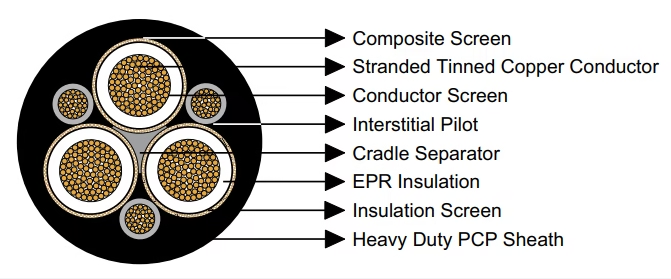
Technical specifications for AS/NZS 1802:2003 Type 240 longwall supply cables featuring three interstitial pilot conductors and reinforced composite earth screening. Detailed engineering data for EPR insulated flexible mining power cables rated 1.1-11kV. Professional guide covering conductor configurations, pilot arrangements, and low-resistance earthing systems for underground machinery feeders.
AS/NZS 1802:2003 Type 240 Longwall Mining Cable
Triple Pilot EPR Insulated Trailing Cable with Enhanced Earthing | Voltage Range: 1.1kV to 11kV
Anhui Feichun Special Cable Co., Ltd.
Specialized engineering and manufacturing of Type 240 longwall supply cables conforming to Australian and New Zealand underground mining standards. Our triple-pilot configuration delivers superior control circuit reliability and low-resistance earth fault protection for critical mining machinery installations.
Product Applications and Operational Context
Type 240 trailing cables represent specialized power distribution conductors engineered for longwall mining operations and high-capacity machinery feeder circuits. These cables distinguish themselves from standard Type 209 configurations through incorporation of three substantial interstitial pilot conductors and enlarged composite screening systems delivering reduced earth impedance characteristics critical for sensitive electronic control systems and rapid fault detection.
Longwall mining methodology employs mechanized coal extraction systems comprising shearer machines, armored face conveyors, and hydraulic roof supports operating in coordinated sequences. Power distribution to these systems demands cables capable of delivering high current capacity while maintaining exceptional earth fault protection and control signal integrity throughout operational cycles spanning multiple shifts without interruption.
Longwall Power Distribution
Primary feeder cables supplying electrical power to longwall shearer equipment, armored face conveyors, and stage loader systems. The three pilot conductors facilitate remote monitoring, interlocking circuits, and emergency shutdown systems essential for coordinated equipment operation.
Continuous Miner Feeders
Main power supply cables for continuous mining machines requiring high ampacity conductors combined with multiple control circuits. Enhanced earth screening provides superior fault current management protecting sensitive variable frequency drive systems.
Mobile Equipment Supply
Feeder installations for shuttle cars, battery haulers, and roof bolting machines demanding both power transmission and comprehensive control signaling capabilities through dedicated pilot conductor pathways.
Main Distribution Circuits
Underground distribution feeders connecting substation equipment to localized load centers. Large core screening configurations ensure minimal earth loop impedance facilitating accurate ground fault detection and rapid protective device operation.
Triple Pilot Conductor Advantage
The Type 240 configuration incorporates three generously-sized interstitial pilot conductors positioned between primary power cores. This arrangement provides dedicated pathways for control systems, instrumentation signals, and communication networks while maintaining physical separation from high-current power conductors. Unlike single-pilot designs, triple-pilot configurations enable redundant control circuits, bidirectional communication protocols, and independent monitoring systems without requiring auxiliary cabling installations.
Regulatory Compliance and Standards Framework
Type 240 cable manufacturing adheres to comprehensive Australian and New Zealand electrical standards governing underground mining cable systems with particular emphasis on earth continuity, insulation coordination, and mechanical durability requirements specific to longwall extraction environments.
- AS/NZS 1802:2003: Principal specification standard establishing construction parameters, material requirements, and testing protocols for reeling and trailing cables deployed in underground mining operations. Type 240 designation represents specific configuration within this standard addressing longwall supply requirements.
- AS/NZS 1125: Conductor manufacturing standard defining stranding methodologies, annealing procedures, and electrical conductivity specifications for copper conductors utilized in flexible mining cable assemblies. Governs both power conductors and pilot conductor constructions.
- AS/NZS 3808: Electrical safety standard establishing installation practices, earthing system requirements, and protective device coordination specific to underground coal mining electrical installations. Addresses fault current calculations and earth impedance limitations.
- AS/NZS 5000.1: General electrical installation code providing comprehensive guidance on cable selection methodologies, routing practices, and environmental protection measures applicable across mining industry applications. Incorporates cross-references to mining-specific standards.
Cable Construction Methodology and Material Selection
Type 240 cables employ sophisticated multi-layer construction strategies where each component fulfills specific electrical, mechanical, or protective requirements. Understanding these construction elements enables informed specification decisions and effective troubleshooting of field performance characteristics.
Detailed Layer-by-Layer Construction Analysis
Flexible stranded tinned annealed copper conductors manufactured from multiple fine-diameter copper wires arranged in concentric stranding patterns. Tinning treatment provides oxidation resistance in humid underground environments while annealing processes reduce work-hardening effects maintaining flexibility throughout service life. Available cross-sections span 6mm² through 300mm² nominal areas accommodating diverse ampacity requirements.
Semiconductive compound applied directly to conductor surfaces in cables rated 3.3/3.3kV and higher. This layer establishes uniform electric field distribution across insulation thickness preventing voltage stress concentrations at conductor surface irregularities. Material exhibits controlled electrical resistivity intermediate between conductor and insulation properties.
Ethylene Propylene Rubber (EPR) elastomeric insulation providing exceptional dielectric strength, thermal stability ranging from -40°C to +90°C continuous operation, and mechanical resilience under repeated flexing. Insulation thickness varies from 1.5mm (low voltage applications) to 7.6mm (11kV configurations) proportional to voltage stress requirements per AS/NZS standards.
Semiconductive elastomer layer bonded to outer insulation surfaces creating equipotential termination plane. This screen ensures radial voltage uniformity and provides low-impedance pathway for capacitive charging currents. Essential component for medium voltage designs preventing surface tracking phenomena and partial discharge initiation.
Hybrid construction combining tinned annealed copper braiding interwoven with high-tensile polyester yarn filaments. Copper braiding dimensions exceed standard trailing cable specifications providing substantially lower earth loop resistance. Polyester yarn contributes mechanical tensile strength without compromising cable flexibility. Screen coverage typically achieves 90-95% circumferential coverage around insulated cores.
Triple pilot conductor assembly represents defining characteristic distinguishing Type 240 from standard trailing cables. Each pilot consists of flexible stranded tinned copper conductor with individual EPR insulation covering. Pilots positioned in interstitial spaces between primary power conductors maintaining geometric separation. Cross-sectional areas range from 7.2mm² to 63.2mm² depending upon primary conductor sizing, substantially larger than single-pilot configurations enabling higher control circuit current capacity and reduced voltage drop in instrumentation circuits.
Semiconductive Polychloroprene (PCP) compound layer maintaining precise geometric spacing between power conductor assembly and pilot conductors. Prevents inter-core abrasion during cable flexing while providing mechanical cushioning. Semiconductive properties facilitate voltage stress equalization across cable cross-section.
Heavy duty Polychloroprene (PCP) sheath delivering comprehensive environmental protection against mechanical abrasion, chemical exposure, moisture penetration, and flame propagation. Standard PCP formulation offers excellent resistance to mineral oils and hydraulic fluids common in mining environments. Alternative Chlorinated Polyethylene (CPE) or Chlorosulfonated Polyethylene (CSP) sheaths available for specialized applications requiring enhanced chemical resistance or elevated temperature performance. Sheath thickness ranges from 3.8mm to 10.7mm proportional to cable diameter.
Technical Specifications Organized by Voltage Classification
Type 240 series manufacturing encompasses four voltage classifications optimized for specific longwall equipment power requirements and distribution system architectures. Selection methodology incorporates voltage rating, ampacity demands, control circuit requirements, and earth fault protection sensitivity.
Type 240.1 – Low Voltage Classification (1.1/1.1kV Rating)
Entry-level voltage rating designed for auxiliary mining equipment, localized machinery, and short-distance power distribution. Minimal insulation thickness maintains optimal flexibility while satisfying voltage stress requirements. Three pilot conductors provide dedicated control and monitoring circuits for equipment automation systems.
Type 240.1 Complete Specifications (1.1/1.1kV)
| Conductor Area (mm²) | Strand Pattern | Insul Thick (mm) | Screen Strand | Pilot Area (mm²) | Pilot Strand | Pilot Cover (mm) | Sheath (mm) | OD (mm) | Weight (kg/100m) |
|---|---|---|---|---|---|---|---|---|---|
| 6 | 84/0.30 | 1.5 | 7/0.25 | 7.2 | 18/0.30 | 1.0 | 3.8 | 30.0 | 131 |
| 10 | 77/0.40 | 1.5 | 7/0.25 | 8.6 | 27/0.30 | 1.0 | 3.8 | 32.6 | 159 |
| 16 | 126/0.40 | 1.6 | 7/0.25 | 9.6 | 42/0.30 | 1.0 | 4.0 | 35.8 | 202 |
| 25 | 209/0.40 | 1.6 | 7/0.25 | 11.3 | 66/0.30 | 1.2 | 4.3 | 39.7 | 265 |
| 35 | 285/0.40 | 1.6 | 7/0.25 | 12.4 | 90/0.30 | 1.2 | 4.6 | 43.1 | 326 |
| 50 | 380/0.40 | 1.7 | 7/0.25 | 14.1 | 120/0.30 | 1.2 | 5.0 | 47.7 | 404 |
| 70 | 203/0.67 | 1.8 | 7/0.25 | 16.5 | 39/0.67 | 1.2 | 5.4 | 53.9 | 533 |
| 95 | 259/0.67 | 2.0 | 7/0.25 | 18.2 | 39/0.67 | 1.2 | 6.0 | 58.6 | 635 |
| 120 | 336/0.67 | 2.1 | 7/0.25 | 20.3 | 42/0.67 | 1.4 | 6.4 | 64.4 | 775 |
| 150 | 427/0.67 | 2.3 | 7/0.25 | 22.3 | 54/0.67 | 1.4 | 6.9 | 70.2 | 940 |
| 185 | 518/0.67 | 2.5 | 7/0.30 | 30.2 | 63/0.67 | 1.4 | 7.4 | 77.4 | 1150 |
| 240 | 672/0.67 | 2.8 | 7/0.30 | 33.6 | 77/0.67 | 1.6 | 8.2 | 86.0 | 1440 |
| 300 | 854/0.67 | 3.0 | 7/0.40 | 50.1 | 98/0.67 | 1.6 | 8.8 | 95.1 | 1810 |
Type 240.3 – Standard Medium Voltage (3.3/3.3kV Rating)
Industry-standard voltage classification for longwall shearer machines, armored face conveyors, and continuous mining equipment. Incorporates conductor screening layers for voltage stress management. Balanced engineering achieving optimal compromise between electrical performance and mechanical flexibility characteristics.
Type 240.3 Complete Specifications (3.3/3.3kV)
| Conductor Area (mm²) | Strand Pattern | Insul Thick (mm) | Screen Strand | Pilot Area (mm²) | Pilot Strand | Pilot Cover (mm) | Sheath (mm) | OD (mm) | Weight (kg/100m) |
|---|---|---|---|---|---|---|---|---|---|
| 16 | 126/0.40 | 3.0 | 7/0.25 | 13.1 | 42/0.30 | 1.4 | 5.3 | 46.2 | 306 |
| 25 | 209/0.40 | 3.0 | 7/0.25 | 14.8 | 66/0.30 | 1.4 | 5.6 | 50.1 | 379 |
| 35 | 285/0.40 | 3.0 | 7/0.25 | 15.8 | 90/0.30 | 1.4 | 5.9 | 53.5 | 444 |
| 50 | 380/0.40 | 3.0 | 7/0.25 | 17.2 | 120/0.30 | 1.4 | 6.3 | 57.6 | 525 |
| 70 | 203/0.67 | 3.0 | 7/0.25 | 18.6 | 39/0.67 | 1.4 | 6.6 | 62.5 | 656 |
| 95 | 259/0.67 | 3.0 | 7/0.25 | 20.3 | 39/0.67 | 1.4 | 7.1 | 66.2 | 750 |
| 120 | 336/0.67 | 3.0 | 7/0.30 | 27.2 | 42/0.67 | 1.6 | 7.4 | 72.0 | 910 |
| 150 | 427/0.67 | 3.0 | 7/0.40 | 39.6 | 54/0.67 | 1.6 | 7.8 | 78.0 | 1115 |
| 185 | 518/0.67 | 3.0 | 7/0.40 | 42.2 | 63/0.67 | 1.8 | 8.2 | 83.4 | 1280 |
| 240 | 672/0.67 | 3.0 | 7/0.40 | 46.6 | 77/0.67 | 1.8 | 8.8 | 90.3 | 1540 |
| 300 | 854/0.67 | 3.0 | 7/0.50 | 63.2 | 98/0.67 | 1.8 | 9.4 | 98.4 | 1920 |
Type 240.6 – Enhanced Medium Voltage (6.6/6.6kV Rating)
Higher voltage classification for large-scale longwall installations, main distribution feeders, and extended underground power transmission circuits. Increased insulation thickness provides enhanced dielectric strength while maintaining acceptable flexibility for trailing applications. Suitable for high-power machinery and long-distance underground distribution.
Type 240.6 Complete Specifications (6.6/6.6kV)
| Conductor Area (mm²) | Strand Pattern | Insul Thick (mm) | Screen Strand | Pilot Area (mm²) | Pilot Strand | Pilot Cover (mm) | Sheath (mm) | OD (mm) | Weight (kg/100m) |
|---|---|---|---|---|---|---|---|---|---|
| 16 | 126/0.40 | 5.0 | 7/0.25 | 17.2 | 42/0.30 | 1.4 | 6.4 | 57.3 | 440 |
| 25 | 209/0.40 | 5.0 | 7/0.25 | 18.6 | 66/0.30 | 1.4 | 6.7 | 61.2 | 521 |
| 35 | 285/0.40 | 5.0 | 7/0.25 | 18.6 | 90/0.30 | 1.6 | 7.0 | 64.6 | 593 |
| 50 | 380/0.40 | 5.0 | 7/0.25 | 21.3 | 120/0.30 | 1.6 | 7.3 | 68.5 | 685 |
| 70 | 203/0.67 | 5.0 | 7/0.25 | 23.4 | 39/0.67 | 1.6 | 7.7 | 73.7 | 830 |
| 95 | 259/0.67 | 5.0 | 7/0.30 | 29.2 | 39/0.67 | 1.6 | 8.1 | 77.8 | 954 |
| 120 | 336/0.67 | 5.0 | 7/0.30 | 31.7 | 42/0.67 | 1.8 | 8.5 | 83.1 | 1111 |
| 150 | 427/0.67 | 5.0 | 7/0.40 | 45.7 | 54/0.67 | 1.8 | 8.9 | 89.1 | 1335 |
| 185 | 518/0.67 | 5.0 | 7/0.40 | 48.4 | 63/0.67 | 1.8 | 9.3 | 94.5 | 1515 |
| 240 | 672/0.67 | 5.0 | 7/0.40 | 52.8 | 77/0.67 | 1.8 | 9.9 | 101.4 | 1810 |
| 300 | 854/0.67 | 5.0 | 7/0.50 | 71.5 | 98/0.67 | 1.8 | 10.4 | 109.3 | 2190 |
Type 240.11 – High Voltage Configuration (11/11kV Rating)
Premium voltage classification for high-power longwall installations and main underground distribution systems. Maximum insulation thickness (7.6mm) delivers superior dielectric performance for elevated voltage stress conditions. Primarily deployed on large longwall systems, main substation feeders, and extended distribution circuits requiring maximum power transmission capacity.
Type 240.11 Complete Specifications (11/11kV)
| Conductor Area (mm²) | Strand Pattern | Insul Thick (mm) | Screen Strand | Pilot Area (mm²) | Pilot Strand | Pilot Cover (mm) | Sheath (mm) | OD (mm) | Weight (kg/100m) |
|---|---|---|---|---|---|---|---|---|---|
| 25 | 209/0.40 | 7.6 | 7/0.25 | 23.7 | 66/0.30 | 2.0 | 8.1 | 75.6 | 752 |
| 35 | 285/0.40 | 7.6 | 7/0.30 | 30.2 | 90/0.30 | 2.0 | 8.4 | 79.7 | 860 |
| 50 | 380/0.40 | 7.6 | 7/0.30 | 31.7 | 120/0.30 | 2.0 | 8.7 | 83.6 | 961 |
| 70 | 203/0.67 | 7.6 | 7/0.30 | 34.1 | 39/0.67 | 2.0 | 9.1 | 88.8 | 1125 |
| 95 | 259/0.67 | 7.6 | 7/0.40 | 47.5 | 39/0.67 | 2.0 | 9.6 | 93.7 | 1300 |
| 120 | 336/0.67 | 7.6 | 7/0.40 | 51.0 | 42/0.67 | 2.2 | 9.9 | 98.8 | 1470 |
| 150 | 427/0.67 | 7.6 | 7/0.40 | 53.7 | 54/0.67 | 2.2 | 10.3 | 103.5 | 1659 |
| 185 | 518/0.67 | 7.6 | 7/0.40 | 57.2 | 63/0.67 | 2.2 | 10.7 | 108.8 | 1880 |
Type 240 vs Type 209: Comparative Technical Analysis
Understanding differences between Type 240 and Type 209 cable configurations enables optimal specification decisions based on application requirements, control circuit complexity, and earth fault protection sensitivity. The following comparison highlights critical performance distinctions.
| Characteristic | Type 209 (Single Pilot) | Type 240 (Triple Pilot) | Advantage |
|---|---|---|---|
| Pilot Conductors | 1 × Central Extensible | 3 × Interstitial | Type 240: Redundant control circuits, higher capacity |
| Pilot Positioning | Central core location | Interstitial spaces between power cores | Type 240: Better electromagnetic isolation |
| Pilot Cross-Section (35mm² example) | 12.4mm² single conductor | 3 × 12.4mm² (total 37.2mm²) | Type 240: 3× total pilot capacity |
| Composite Screen Size | Standard dimensioning | Enhanced/oversized configuration | Type 240: Lower earth resistance |
| Earth Fault Detection | Standard sensitivity | Enhanced sensitivity (low impedance) | Type 240: Faster fault detection, improved safety |
| Control Circuit Applications | Basic control, single channel | Complex automation, redundant systems | Type 240: Advanced control capabilities |
| Weight (35mm²@3.3kV) | 431 kg/100m | 444 kg/100m | Type 209: Marginally lighter |
| Overall Diameter (35mm²@3.3kV) | 53.5mm | 53.5mm | Equivalent dimensions |
| Ideal Applications | General trailing, basic machinery | Longwall systems, complex automation | Application-specific |
| Cost Factor | Baseline | +8-12% premium | Type 209: Lower initial cost |
Installation Practices and Operational Guidelines
Proper installation methodologies maximize Type 240 cable service life and prevent premature failures resulting from mechanical damage, excessive bending stress, or environmental exposure. Longwall installations present unique challenges requiring specialized handling procedures and protective measures.
Minimum Bending Radius Requirements
Cable routing must observe minimum bending radius specifications preventing insulation damage and conductor strand fracture. Recommended minimums: 6× overall diameter for Type 240.1, 8× diameter for Type 240.3, 10× diameter for Type 240.6, and 12× diameter for Type 240.11. Tighter radii impose excessive mechanical stress on conductor strands, insulation interfaces, and pilot conductor assemblies promoting accelerated fatigue failure.
Pilot Conductor Termination Practices
Three-pilot configuration requires specialized termination procedures ensuring proper conductor identification, segregation from power circuits, and adequate strain relief. Pilot conductors typically terminate to control system junction boxes or programmable logic controller input modules. Maintain minimum 10mm separation between pilot and power conductor terminations preventing electromagnetic interference and inadvertent cross-connection. Employ color-coded identification labels documenting pilot function (monitoring, control, communication) facilitating maintenance activities.
Enhanced Earth System Integration
Type 240 composite screen dimensions provide substantially lower earth loop resistance compared to standard trailing cables. Capitalize on this characteristic by implementing comprehensive earthing strategies. Connect composite screen to equipment earth terminals using appropriate gland hardware maintaining screen continuity throughout cable length. Verify earth loop impedance post-installation confirming values below 0.5 ohms enabling rapid protective device operation during ground fault conditions.
Longwall-Specific Protection Measures
Longwall face installations subject cables to unique hazards including roof rock falls, equipment pinch points, and coal dust accumulation. Implement protective measures including cable ramps across traffic paths, suspended catenary systems in gateroad entries, and protective chutes guiding cables through equipment transfer points. Support spacing typically 2.0-3.0 meter intervals depending upon cable weight and installation geometry. Inspect daily for sheath damage, exposed conductors, or pilot insulation deterioration particularly at equipment connection points and high-stress flexure zones.
Professional Engineering Review and Authorship
This comprehensive technical specification represents collaborative engineering analysis compiled by electrical professionals specializing in underground coal mining power distribution systems and longwall installation methodologies. Our combined expertise encompasses design, specification, installation supervision, and maintenance of mining electrical infrastructure across major Australian coal operations, metalliferous mining facilities, and international mining projects.
Technical content verification performed by licensed electrical engineers maintaining current certification under AS/NZS 3000 wiring rules with specialized qualifications in underground coal mine electrical systems conforming to Coal Mine Health and Safety Regulations and AS/NZS 3000 series standards. Practical experience includes direct involvement with longwall electrical installations spanning shearer power systems, armored face conveyor supply circuits, and underground distribution networks supporting continuous production operations.
Author Credentials and Industry Experience
- Educational Background: Bachelor of Electrical Engineering (Power Systems) from accredited Australian university. Postgraduate certificate in Mine Electrical Engineering with emphasis on underground power distribution and hazardous area electrical installations.
- Professional Licensing: Unrestricted Class A Electrical License authorizing high-voltage installations. Coal Mine Electrical Certificate of Competency qualifying underground coal mine electrical supervision. Registered Professional Engineer with Engineers Australia.
- Longwall Mining Experience: Twelve years specialized experience with longwall electrical systems including involvement in five greenfield longwall installations and numerous panel moves. Direct responsibility for cable specification, procurement verification, installation supervision, and commissioning activities across underground coal operations.
- Port Facility Background: Eight years electrical maintenance experience with bulk material handling port facilities managing shore-to-ship power systems, quayside conveyor installations, and shiploading equipment electrical infrastructure. Expertise in harsh environment cable applications subject to salt spray, UV exposure, and heavy mechanical loading.
- Heavy Industry Expertise: Industrial maintenance and project management experience spanning steel production facilities, cement manufacturing operations, and large-scale material processing installations. Comprehensive understanding of high-power distribution systems, motor control centers, and flexible cable applications for automated machinery.
- Standards Knowledge: In-depth familiarity with Australian/New Zealand electrical standards (AS/NZS series), International Electrotechnical Commission (IEC) specifications, and coal mining-specific regulations. Active participation in mining industry electrical safety working groups and standards development committees.
- Continuing Professional Development: Regular attendance at mining electrical engineering conferences, manufacturer technical training programs, and professional development seminars. Maintain active membership in professional engineering societies including Engineers Australia and AusIMM (Australasian Institute of Mining and Metallurgy).
Technical specifications and installation recommendations provided represent general engineering guidance applicable to typical longwall mining applications. Specific projects require detailed engineering analysis incorporating site-specific geological conditions, equipment specifications, ventilation constraints, and regulatory requirements. Consultation with licensed electrical engineering professionals possessing underground coal mine experience strongly recommended for critical installations.


