
Professional technical guide to AS/NZS 1802:2003 Type 209 mine trailing cables. Comprehensive specifications for EPR insulated, tinned copper conductor flexible power cables rated 1.1-11kV. Includes conductor sizing, insulation thickness, screening parameters, and weight calculations for underground mining machinery, drills, and mobile equipment. Expert analysis from certified electrical engineers with port and mining experience.
AS/NZS 1802:2003 Type 209 Mine Trailing Cable
EPR Insulated Heavy Duty Flexible Power Cable for Mining Operations | Voltage Rating: 1.1kV to 11kV
Anhui Feichun Special Cable Co., Ltd.
Specialized manufacturer of industrial-grade mining cables conforming to Australian and New Zealand electrical standards. Our Type 209 series represents engineered solutions for harsh underground environments requiring maximum mechanical durability and electrical reliability.
Product Overview and Industrial Applications
The Type 209 series trailing cable represents a specialized category of flexible power transmission conductors engineered specifically for mobile mining machinery and portable drilling equipment operating in underground and surface mining environments. These cables deliver reliable electrical power to equipment subjected to continuous mechanical stress, abrasion, moisture exposure, and chemical contaminants typical of mineral extraction operations.
Distinguished from stationary installation cables, trailing cables must accommodate frequent flexing, dragging across uneven terrain, exposure to sharp rock fragments, and occasional submersion in water or contact with mineral oils. The Type 209 construction methodology addresses these operational challenges through multi-layer protective systems incorporating elastomeric insulation, composite metallic screening, and reinforced polymeric sheathing materials.
Mobile Mining Equipment
Continuous miners, shuttle cars, load-haul-dump vehicles, and underground haulage systems requiring flexible power feeds during operational movement within mining galleries and extraction faces.
Drilling Apparatus
Rotary drill rigs, percussion drilling machines, and exploratory boring equipment demanding small cross-section cables (6mm² to 35mm²) with superior flexibility characteristics.
Portable Tools and Machinery
Handheld rock drills, hydraulic breakers, ventilation fans, and auxiliary equipment requiring lightweight cable constructions with enhanced conductor strand configurations.
Surface Mining Operations
Draglines, walking excavators, and mobile crushing units operating in open-pit environments exposed to ultraviolet radiation, temperature extremes, and mechanical impact hazards.
Compliance Standards and Regulatory Framework
Manufacturing specifications for Type 209 trailing cables adhere to comprehensive Australian and New Zealand electrical standards governing underground mining cable systems. Compliance verification ensures operational safety, electromagnetic compatibility, and environmental durability across diverse geological conditions.
- AS/NZS 1802:2003: Primary specification standard defining construction requirements, material properties, and performance testing protocols for reeling and trailing cables utilized in mining operations.
- AS/NZS 1125: Conductors specification governing stranding configurations, annealing processes, and electrical conductivity requirements for copper conductors employed in flexible cable assemblies.
- AS/NZS 3808: Electrical safety standard establishing installation practices, earthing requirements, and protective device coordination for mining cable systems.
- AS/NZS 5000.1: Electrical installations code providing comprehensive guidance on cable selection, routing methodologies, and environmental protection measures specific to mining environments.
- AS/NZS 2802:2000: Supplementary standard addressing specific requirements for electrical equipment and cable systems in underground coal mining applications.
- AS/NZS 1972:2006: Standard governing flexible cords and cables, providing additional specifications for portable equipment power supply conductors.
Cable Construction and Material Engineering
The Type 209 trailing cable employs a sophisticated multi-layer construction strategy where each component serves specific electrical, mechanical, or protective functions. Understanding these layers enables informed cable selection and troubleshooting of field performance issues.
Layer-by-Layer Construction Analysis
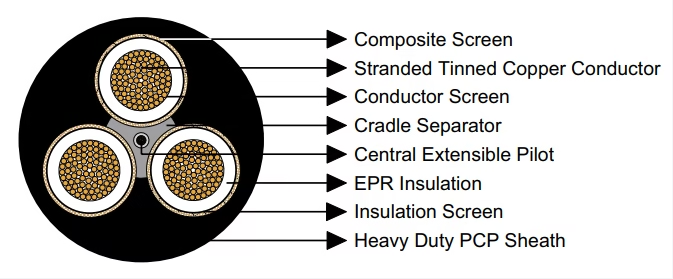
Flexible stranded tinned annealed copper conductor manufactured from multiple fine-gauge copper wires twisted in concentric layers. Tinning provides oxidation resistance and improves solderability. Annealing process reduces work hardening, maintaining flexibility after repeated bending cycles. Conductor sizes range from 6mm² to 300mm² nominal cross-sectional area.
Semiconductive compound layer applied to conductors in cables rated 3.3/3.3kV and above. This layer maintains uniform electric field distribution across the insulation thickness, preventing voltage stress concentrations at conductor irregularities. Material exhibits controlled electrical resistivity between conductor and insulation interface.
Ethylene Propylene Rubber (EPR) elastomeric insulation providing exceptional dielectric strength, thermal stability, and mechanical resilience. EPR maintains insulation integrity across temperature ranges from -40°C to +90°C continuous operation. Thickness varies from 1.5mm (low voltage) to 7.6mm (11kV ratings) proportional to voltage stress requirements.
Semiconductive elastomer layer bonded to the outer insulation surface creating equipotential termination plane. This screen ensures uniform radial voltage distribution and provides low-resistance connection path for capacitive charging currents. Essential for medium voltage cable designs preventing surface tracking and partial discharge phenomena.
Hybrid construction combining tinned annealed copper braiding interwoven with high-strength polyester yarn filaments. Copper braiding provides low-impedance earth fault current path while polyester yarn contributes mechanical tensile strength. This composite approach achieves electrical grounding functionality without sacrificing cable flexibility. Screening coverage typically exceeds 85% of insulated core circumference.
Semiconductive Polychloroprene (PCP) compound layer maintaining geometric spacing between power conductors. Prevents core-to-core abrasion during cable flexing and provides additional mechanical cushioning. Semiconductive properties facilitate voltage equalization across three-phase conductor assembly.
Dedicated signaling or control conductor positioned at cable geometric center. Flexible stranded tinned copper construction (typically 7 strands) with individual EPR insulation layer. Extends slightly beyond power conductors during cable stretching, preventing pilot conductor fracture under tensile loading. Nominal cross-sections range from 7.2mm² to 71.5mm² depending on primary conductor size.
Heavy duty Polychloroprene (PCP) sheath providing comprehensive environmental protection against mechanical abrasion, chemical exposure, moisture ingress, and ultraviolet degradation. Standard PCP sheath offers excellent oil resistance and flame-retardant properties. Alternative Chlorinated Polyethylene (CPE) or Chlorosulfonated Polyethylene (CSP) sheaths available upon specification for enhanced chemical resistance or elevated temperature applications. Sheath thickness ranges from 3.8mm to 10.4mm proportional to overall cable diameter.
Technical Specifications by Voltage Classification
Type 209 series cables manufacture across four distinct voltage categories, each optimized for specific equipment power requirements and operational environments. Selection criteria incorporate voltage rating, current-carrying capacity, mechanical flexibility demands, and installation environment characteristics.
Type 209.1 – Low Voltage Configuration (1.1/1.1kV Rating)
Entry-level voltage classification designed for portable tools, handheld drilling equipment, and low-power auxiliary machinery. Insulation thickness minimized to maintain superior flexibility while meeting voltage stress requirements. Optimal for applications requiring frequent cable manipulation and compact storage characteristics.
Type 209.1 Detailed Specifications (1.1/1.1kV)
| Conductor Size (mm²) | Stranding Config | Insulation Thick (mm) | Screen Stranding | Pilot Size (mm²) | Sheath Thick (mm) | Overall Diameter (mm) | Weight (kg/100m) |
|---|---|---|---|---|---|---|---|
| 6 | 84/0.30 | 1.5 | 24/0.20 | 7.2 | 3.8 | 30.0 | 129 |
| 10 | 77/0.40 | 1.5 | 24/0.20 | 8.6 | 3.8 | 32.6 | 157 |
| 16 | 126/0.40 | 1.6 | 24/0.20 | 9.6 | 4.0 | 35.8 | 197 |
| 25 | 209/0.40 | 1.6 | 24/0.20 | 11.3 | 4.3 | 39.7 | 255 |
| 35 | 285/0.40 | 1.6 | 24/0.20 | 12.4 | 4.6 | 43.1 | 312 |
| 50 | 380/0.40 | 1.7 | 40/0.20 | 14.1 | 5.0 | 47.7 | 386 |
| 70 | 203/0.67 | 1.8 | 40/0.20 | 16.5 | 5.4 | 52.8 | 503 |
| 95 | 259/0.67 | 2.0 | 40/0.20 | 18.2 | 6.0 | 58.6 | 605 |
| 120 | 336/0.67 | 2.1 | 40/0.20 | 20.3 | 6.4 | 64.4 | 741 |
| 150 | 427/0.67 | 2.3 | 40/0.20 | 22.3 | 6.9 | 70.2 | 896 |
| 185 | 518/0.67 | 2.5 | 40/0.20 | 30.2 | 7.4 | 77.4 | 1092 |
| 240 | 672/0.67 | 2.8 | 40/0.20 | 33.6 | 8.2 | 86.0 | 1365 |
| 300 | 854/0.67 | 3.0 | 40/0.20 | 50.1 | 8.8 | 95.1 | 1715 |
Type 209.3 – Medium Voltage Configuration (3.3/3.3kV Rating)
Standard industrial voltage classification suitable for continuous mining machines, shuttle cars, and medium-scale drilling apparatus. Incorporates conductor screening layers for voltage stress management. Balanced design achieving optimal compromise between electrical performance and mechanical flexibility requirements.
Type 209.3 Detailed Specifications (3.3/3.3kV)
| Conductor Size (mm²) | Stranding Config | Insulation Thick (mm) | Screen Stranding | Pilot Size (mm²) | Sheath Thick (mm) | Overall Diameter (mm) | Weight (kg/100m) |
|---|---|---|---|---|---|---|---|
| 16 | 126/0.40 | 3.0 | 24/0.20 | 13.1 | 5.3 | 46.2 | 301 |
| 25 | 209/0.40 | 3.0 | 24/0.20 | 14.8 | 5.6 | 50.1 | 369 |
| 35 | 285/0.40 | 3.0 | 24/0.20 | 15.8 | 5.9 | 53.5 | 431 |
| 50 | 380/0.40 | 3.0 | 40/0.20 | 17.2 | 6.3 | 57.6 | 507 |
| 70 | 203/0.67 | 3.0 | 40/0.20 | 18.6 | 6.6 | 62.5 | 624 |
| 95 | 259/0.67 | 3.0 | 40/0.20 | 20.3 | 7.1 | 66.2 | 719 |
| 120 | 336/0.67 | 3.0 | 40/0.20 | 27.2 | 7.4 | 72.0 | 876 |
| 150 | 427/0.67 | 3.0 | 40/0.20 | 39.6 | 7.8 | 78.0 | 1072 |
| 185 | 518/0.67 | 3.0 | 40/0.20 | 42.2 | 8.2 | 83.4 | 1236 |
| 240 | 672/0.67 | 3.0 | 40/0.20 | 46.6 | 8.8 | 90.3 | 1500 |
| 300 | 854/0.67 | 3.0 | 40/0.20 | 63.2 | 9.4 | 98.4 | 1840 |
Type 209.6 – Enhanced Medium Voltage (6.6/6.6kV Rating)
Higher voltage classification for large-scale underground mining machinery including draglines, electric rope shovels, and primary ventilation systems. Increased insulation thickness provides enhanced dielectric strength while maintaining acceptable flexibility for trailing applications. Suitable for long-distance power transmission within mine workings.
Type 209.6 Detailed Specifications (6.6/6.6kV)
| Conductor Size (mm²) | Stranding Config | Insulation Thick (mm) | Screen Stranding | Pilot Size (mm²) | Sheath Thick (mm) | Overall Diameter (mm) | Weight (kg/100m) |
|---|---|---|---|---|---|---|---|
| 16 | 126/0.40 | 5.0 | 24/0.20 | 17.2 | 6.4 | 57.3 | 435 |
| 25 | 209/0.40 | 5.0 | 24/0.20 | 18.6 | 6.7 | 61.2 | 512 |
| 35 | 285/0.40 | 5.0 | 24/0.20 | 18.6 | 7.0 | 64.6 | 582 |
| 50 | 380/0.40 | 5.0 | 40/0.20 | 21.3 | 7.3 | 68.5 | 668 |
| 70 | 203/0.67 | 5.0 | 40/0.20 | 23.4 | 7.7 | 73.7 | 799 |
| 95 | 259/0.67 | 5.0 | 40/0.20 | 29.2 | 8.1 | 77.8 | 935 |
| 120 | 336/0.67 | 5.0 | 40/0.20 | 31.7 | 8.5 | 83.1 | 1090 |
| 150 | 427/0.67 | 5.0 | 40/0.20 | 45.7 | 8.9 | 89.1 | 1310 |
| 185 | 518/0.67 | 5.0 | 40/0.20 | 48.4 | 9.3 | 94.5 | 1480 |
| 240 | 672/0.67 | 5.0 | 40/0.20 | 52.8 | 9.9 | 101.4 | 1750 |
| 300 | 854/0.67 | 5.0 | 40/0.20 | 71.5 | 10.4 | 109.3 | 2120 |
Type 209.11 – High Voltage Configuration (11/11kV Rating)
Premium voltage classification for high-power mining machinery and extended distribution circuits within large-scale mining complexes. Maximum insulation thickness (7.6mm) provides superior dielectric performance for high-voltage stress conditions. Primarily deployed on walking draglines, bucket-wheel excavators, and main distribution feeders requiring maximum power transmission capacity.
Type 209.11 Detailed Specifications (11/11kV)
| Conductor Size (mm²) | Stranding Config | Insulation Thick (mm) | Screen Stranding | Pilot Size (mm²) | Sheath Thick (mm) | Overall Diameter (mm) | Weight (kg/100m) |
|---|---|---|---|---|---|---|---|
| 25 | 209/0.40 | 7.6 | 24/0.20 | 23.7 | 8.1 | 75.6 | 750 |
| 35 | 285/0.40 | 7.6 | 24/0.20 | 30.2 | 8.4 | 79.7 | 858 |
| 50 | 380/0.40 | 7.6 | 40/0.20 | 31.7 | 8.7 | 83.6 | 960 |
| 70 | 203/0.67 | 7.6 | 40/0.20 | 34.1 | 9.1 | 88.8 | 1093 |
| 95 | 259/0.67 | 7.6 | 40/0.20 | 47.5 | 9.6 | 93.7 | 1267 |
| 120 | 336/0.67 | 7.6 | 40/0.20 | 51.0 | 9.9 | 98.8 | 1436 |
| 150 | 427/0.67 | 7.6 | 40/0.20 | 53.7 | 10.3 | 103.5 | 1614 |
| 185 | 518/0.67 | 7.6 | 40/0.20 | 57.2 | 10.7 | 108.8 | 1830 |
Comparative Analysis: Voltage Rating Selection Criteria
Selecting appropriate voltage classification requires comprehensive analysis of equipment specifications, operational environment, transmission distance, and safety regulations. The following comparison matrix facilitates informed decision-making across Type 209 variants.
| Parameter | Type 209.1 (1.1kV) | Type 209.3 (3.3kV) | Type 209.6 (6.6kV) | Type 209.11 (11kV) |
|---|---|---|---|---|
| Conductor Screening | Not Required | Semiconductive Layer | Semiconductive Layer | Semiconductive Layer |
| Minimum Insulation Thickness | 1.5mm | 3.0mm | 5.0mm | 7.6mm |
| Flexibility Rating | Excellent | Very Good | Good | Moderate |
| Weight (35mm² example) | 312 kg/100m | 431 kg/100m | 582 kg/100m | 858 kg/100m |
| Diameter (35mm² example) | 43.1mm | 53.5mm | 64.6mm | 79.7mm |
| Primary Applications | Portable tools, drills, small machinery | Continuous miners, shuttle cars, medium equipment | Large mining equipment, ventilation systems | Draglines, main distribution, high-power machinery |
| Transmission Distance | Short (0-50m) | Medium (50-200m) | Extended (200-500m) | Long (500m+) |
| Cost Factor | Baseline | +35-45% | +80-100% | +150-180% |
| Installation Complexity | Simple | Moderate | Complex | Very Complex |
| Minimum Bend Radius | 6 × Diameter | 8 × Diameter | 10 × Diameter | 12 × Diameter |
Stranding Configuration and Conductor Technology
Conductor stranding methodology directly influences cable flexibility, current-carrying capacity, and mechanical durability. Type 209 series employs fine-gauge copper wire configurations achieving optimal balance between electrical conductivity and mechanical resilience under repeated flexing cycles.
Stranding Notation Interpretation
Conductor specifications utilize notation format: Number/Diameter (e.g., 84/0.30). The first value indicates quantity of individual copper wires while second value specifies diameter in millimeters. Therefore 84/0.30 designation represents eighty-four copper wires each measuring 0.30mm diameter concentrically stranded into single conductor assembly.
Tinning Process Benefits
Annealed copper conductors receive electroplated tin coating serving multiple protective functions. Tinning inhibits oxidation of copper surfaces preventing conductivity degradation in humid mining environments. Additionally, tin coating facilitates soldering operations during termination procedures and provides galvanic protection against corrosion when contacting dissimilar metals within cable glands or connectors.
Current-Carrying Capacity Considerations
Ampacity determination requires analysis of conductor temperature limitations, ambient operating conditions, installation method, and thermal dissipation characteristics. EPR insulation permits continuous conductor temperatures reaching 90°C under normal operation with emergency overload capability to 130°C for limited duration. Actual current ratings depend upon specific installation parameters including cable grouping, ventilation availability, and ambient temperature profiles.
Installation Guidelines and Operational Practices
Proper installation techniques maximize cable service life and prevent premature failures resulting from mechanical damage, excessive bending, or environmental exposure. Mining industry best practices emphasize protective measures addressing unique challenges of underground and surface mining environments.
Minimum Bending Radius Requirements
Cable routing must observe minimum bending radius specifications preventing insulation damage and conductor strand fracture. General guideline establishes minimum bend radius as multiple of overall cable diameter: 6× diameter for Type 209.1, increasing to 12× diameter for Type 209.11 reflecting reduced flexibility of thick-insulation high-voltage configurations. Tighter bending radii impose excessive mechanical stress on conductor strands and insulation interfaces promoting premature failure.
Cable Support and Protection Systems
Trailing cable installations require protective measures preventing mechanical damage from vehicle traffic, material movement, and sharp rock fragments. Common protection methods include cable ramps, suspended catenary systems, drag chain assemblies, and protective conduits in high-traffic zones. Support spacing typically ranges from 1.5m to 3.0m intervals depending upon cable weight and environmental conditions.
Termination and Connection Practices
Electrical terminations represent critical failure points requiring meticulous installation procedures. Medium voltage configurations (Type 209.3 and above) necessitate specialized cable glands maintaining insulation screen continuity and providing environmental sealing. Termination procedures must address screen earthing, stress relief cone installation, and compound application preventing moisture ingress and surface tracking phenomena.
Periodic Inspection and Maintenance
Preventive maintenance programs should incorporate regular visual inspections identifying sheath damage, conductor exposure, or insulation deterioration. Electrical testing protocols include insulation resistance measurements, earth continuity verification, and periodic high-potential testing confirming continued dielectric integrity. Replace cables exhibiting sheath cuts exceeding 10% wall thickness, exposed conductor strands, or insulation resistance values below 1 megohm per kilometer operating voltage.


