
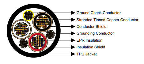
Premium SHD-GC 15kV portable power cable with advanced TPU jacket for draglines, shovels, dredges, drilling rigs. Exceptional abrasion resistance, superior flexibility, EPR insulation. ICEA S-75-381 compliant. Available 2 AWG through 4/0 AWG conductor sizes.
International Line: +86 13855123218
SHD-GC Three-Conductor Round Portable Power Cable featuring Advanced Thermoplastic Polyurethane Jacket Technology – 15kV Voltage Classification
SERIES: SHD-GC | RATED VOLTAGE: 15000V | JACKET TYPE: TPUHigh-performance flexible power transmission cable optimized for mobile industrial machinery operating in challenging environments requiring superior mechanical durability. This SHD-GC cable variant incorporates state-of-the-art thermoplastic polyurethane jacketing technology, delivering exceptional resistance to abrasion, cuts, tears, and environmental degradation while maintaining outstanding flexibility characteristics essential for mobile equipment power distribution systems across mining, dredging, and construction industries.
Industrial Equipment Categories and Operational Scenarios
This cable design specifically addresses power distribution requirements for large-scale mobile machinery that operates in environments where traditional rubber-jacketed cables experience accelerated wear and premature failure. The advanced TPU jacket technology provides significantly extended service life in applications involving frequent cable movement, contact with abrasive materials, and exposure to temperature extremes. Target equipment classifications encompass:
- Walking Dragline Excavators: Electrical power supply for bucket-wheel and dragline excavators utilized in large-scale open-pit mining operations. These massive machines require trailing cables capable of withstanding continuous dragging across irregular terrain while maintaining electrical integrity. The TPU jacket’s superior abrasion resistance significantly extends cable replacement intervals compared to conventional rubber compounds, reducing operational costs and minimizing production interruptions.
- Electric Mining Shovels: Primary power feeders for electric rope shovels and face shovels employed in surface mining and quarrying. The cable must accommodate the shovel’s continuous duty cycle including digging, swinging, dumping, and repositioning movements. TPU’s exceptional cut resistance protects against damage from contact with sharp rock fragments and excavated materials, while the material’s flexibility facilitates cable management around the shovel’s operating radius.
- Hydraulic and Mechanical Dredges: Power transmission systems for cutter suction dredges, hopper dredges, and bucket dredges operating in ports, waterways, and marine construction projects. These applications demand cables that resist water absorption, maintain flexibility in marine environments, and withstand abrasion from contact with dredged materials containing sand, gravel, and debris. TPU’s hydrolytic stability ensures long-term performance in wet conditions where traditional materials degrade.
- Rotary Drilling Rigs: Portable power connections for blast hole drills, exploration drills, and production drilling equipment requiring frequent relocation across mine sites. The cable construction accommodates the mechanical stresses associated with rig mobility while the TPU jacket resists damage from contact with drill cuttings, ensuring reliable power delivery throughout extended drilling campaigns.
- Temporary Power Distribution Networks: Mobile feeder cables for construction sites, mining camps, and industrial facilities requiring relocatable electrical infrastructure. The combination of flexibility, durability, and environmental resistance makes this cable ideal for temporary installations where equipment is frequently reconfigured and cables experience rough handling during deployment and retrieval operations.
Regulatory Standards and Manufacturing Compliance
Cable manufacturing processes conform to internationally recognized standards governing portable power cables for industrial and mining applications. Adherence to these specifications ensures product compatibility with global equipment installations and compliance with regional electrical safety codes:
- ICEA S-75-381 in conjunction with NEMA WC 58: These coordinated standards published by the Insulated Cable Engineers Association and National Electrical Manufacturers Association establish comprehensive requirements for portable and power feeder cables used in mining environments. The standards specify minimum conductor sizes, insulation thickness requirements, voltage ratings, ampacity calculations, and mechanical performance criteria ensuring cables meet rigorous operational demands.
- ASTM B 172: This specification from the American Society for Testing and Materials defines construction requirements for rope-lay-stranded copper conductors incorporating bunch-stranded members. The standard ensures conductors possess optimal flexibility while maintaining structural integrity under repeated flexing cycles typical of portable cable applications.
- ASTM B 33: Standard specification governing tinned copper wire for electrical purposes. This specification establishes requirements for tin coating thickness, adhesion, and uniformity, ensuring the coating provides effective corrosion protection and maintains solderability for field terminations.
- CAN/CSA C22.2 No. 96: Canadian Standards Association requirements for portable power cables. Compliance with this standard ensures cable suitability for Canadian mining and industrial installations, providing additional verification of safety and performance characteristics.
Component Materials and Assembly Architecture
Conductor Element Design
Phase conductors utilize high-conductivity annealed copper wire assembled in concentric rope-lay configuration to maximize flexibility. The annealing process relieves internal stresses in the copper, significantly enhancing ductility and fatigue resistance necessary for cables subjected to continuous movement. Individual copper strands receive electrolytic tin coating providing a protective barrier against oxidation and sulfidation. The tinning process prevents formation of copper oxide on strand surfaces, which would increase contact resistance between individual strands and degrade overall conductor performance. Conductor sizes span from 2 AWG through 4/0 AWG, accommodating current requirements ranging from 164 to 325 amperes under standard rating conditions.
Semiconducting Conductor Shield Layer
A factory-extruded semiconducting polymeric compound envelopes each conductor prior to insulation application. This conductive layer serves critical functions within the cable’s electrical design: it establishes intimate contact with the conductor surface eliminating microscopic air gaps, provides a smooth cylindrical interface for uniform insulation extrusion, controls electrical stress distribution within the insulation system, and prevents corona discharge at the conductor-insulation interface. The material’s semiconducting properties ensure the entire conductor surface remains at the same electrical potential.
Primary Dielectric Insulation
Ethylene Propylene Rubber (EPR) compound forms the main insulation barrier between conductors and ground. EPR was selected for its superior electrical and physical properties in portable cable applications. The material exhibits outstanding dielectric strength enabling 15kV operation with appropriate safety margin. EPR demonstrates exceptional resistance to thermal degradation, maintaining mechanical and electrical integrity through thousands of thermal cycles between minimum and maximum operating temperatures. The compound resists moisture penetration preventing insulation degradation in wet environments common to mining and marine operations. EPR also exhibits excellent resistance to ozone exposure, which causes surface cracking and degradation in natural rubber compounds. Insulation wall thickness measures 0.210 inches (5.3mm) providing adequate dielectric strength for the 15kV voltage rating with appropriate safety factor per industry standards.
Insulation Shield Assembly
A composite shielding system is applied over the EPR insulation layer. The inner shield component consists of semiconducting tape applied helically around the insulation, maintaining electrical contact with the outer insulation surface and confining the dielectric field within the insulation structure. Over this tape, a composite braid combining tinned copper strands and textile fibers provides multiple functions: mechanical reinforcement preventing insulation damage during handling, an equipotential surface eliminating surface potential gradients, and a low-impedance pathway for ground fault currents enabling rapid protective device operation.
Ground Integrity Monitor Conductor
A separate monitoring conductor fabricated from tinned copper strands runs parallel to the phase conductors throughout the cable assembly. This conductor features bright yellow polypropylene insulation for immediate visual identification during installation and maintenance operations. The ground check conductor enables real-time monitoring of grounding system integrity through specialized instrumentation, providing advance warning of ground connection degradation that could create safety hazards. This feature is particularly valuable in mining environments where reliable grounding is essential for personnel protection.
Equipment Grounding Conductor
A full-size grounding conductor constructed from tinned copper strands is integrated within the cable assembly. This conductor’s cross-sectional area is proportioned relative to the phase conductors ensuring adequate capacity to safely conduct fault currents. During ground fault events, this conductor provides the primary return path enabling protective devices to detect and clear faults rapidly, limiting duration of hazardous voltage conditions and preventing equipment damage.
Thermoplastic Polyurethane Jacket System
The complete cable assembly is enclosed in a precision-extruded Thermoplastic Polyurethane (TPU) jacket engineered to provide superior mechanical and environmental protection. TPU represents an advanced polymer technology offering performance characteristics superior to traditional rubber and thermoplastic compounds. The material demonstrates exceptional abrasion resistance—testing typically shows TPU lasting 5-10 times longer than comparable rubber compounds in accelerated wear tests. TPU exhibits outstanding cut and tear resistance protecting against damage from sharp objects and mechanical impacts. The material maintains flexibility across an extremely wide temperature range from -40°C to +90°C, remaining pliable at arctic temperatures where rubber compounds become brittle. TPU demonstrates excellent resistance to mineral oils, hydraulic fluids, and common industrial solvents encountered in mining and construction environments. The material’s hydrolytic stability ensures long-term performance in wet conditions without degradation. TPU also exhibits superior ozone and UV resistance compared to natural and synthetic rubbers. The black pigmented compound incorporates UV stabilizers and antioxidants for enhanced weathering resistance. Jacket wall thickness ranges from 0.235 to 0.265 inches (6.0 to 6.7mm) depending on cable size, providing robust mechanical protection while maintaining reasonable flexibility and overall cable diameter.
Alternative Materials and Custom Configurations
Specialized Jacket Compound Options: While TPU provides optimal performance for most applications, alternative jacket materials can be manufactured for specialized operating conditions. Available compounds include Chlorinated Polyethylene (CPE) for applications requiring maximum abrasion resistance with good chemical properties, Chlorosulfonated Polyethylene (CSP) offering enhanced weather resistance and superior chemical resistance for aggressive environments, Polychloroprene (PCP) providing moderate oil resistance with excellent physical properties, Nitrile Butadiene Rubber (NBR) delivering outstanding resistance to petroleum products and hydraulic oils, and Polyvinyl Chloride (PVC) for cost-sensitive applications with moderate environmental exposure.
Reinforced Dual-Layer Construction: For extreme-duty applications experiencing severe mechanical abuse, a reinforced two-layer jacket incorporating high-strength textile or aramid fiber reinforcement between inner and outer jacket layers can be engineered. This construction dramatically increases tear propagation resistance, provides enhanced cut-through protection, improves overall tensile strength, and extends cable operational life in the most demanding environments.
Physical Properties and Operating Limitations
Installation Bend Radius Specification: Eight times the cable’s nominal outside diameter represents the minimum allowable bending radius during installation and operation. Bending cables more tightly risks conductor deformation, insulation system damage, or shield disruption potentially leading to premature cable failure. All cable routing must maintain this minimum radius including at termination points, support locations, and equipment connection interfaces.
Continuous Conductor Temperature Rating: 90°C (194°F) maximum. This temperature represents the highest continuous conductor operating temperature without degradation of insulation properties. The EPR insulation system maintains full electrical and mechanical integrity at this temperature indefinitely. Current capacity ratings are calculated based on this maximum conductor temperature combined with specified ambient conditions.
Ambient Operating Temperature Range: The cable assembly maintains full functionality across ambient temperatures from -40°C to +70°C. The TPU jacket retains flexibility at extreme low temperatures while the EPR insulation resists thermal softening at elevated temperatures. This wide operating range enables cable deployment across diverse geographical locations and seasonal conditions without performance degradation.
Electrical Stress Rating: The insulation system design provides continuous operation capability at 15kV phase-to-ground voltage with appropriate safety margin. Factory high-potential testing verifies insulation integrity at voltages substantially exceeding operating voltage, ensuring adequate margin for voltage transients and temporary overvoltage conditions that may occur during system operations.
Complete Technical Specifications and Performance Data
The following comprehensive technical data sheet presents complete specifications for all standard configurations within the SHD-GC 15kV TPU-jacketed series. Conductor dimensions conform to American Wire Gauge (AWG) standards with numerical designations indicating relative conductor size. Current capacity values are determined using ICEA S-75-381 calculation methodology assuming 90°C maximum conductor temperature and 40°C ambient air temperature representing typical industrial operating conditions.
| Cable Configuration | Conductor Strands | Ground Conductor | Check Conductor | Insulation Wall | Jacket Wall | Cable OD | Unit Weight | Current Rating |
|---|---|---|---|---|---|---|---|---|
| (Conductors × Size) | (Count) | (AWG/kcmil) | (AWG) | inch (mm) | inch (mm) | inch (mm) | lbs/kft (kg/km) | (Amperes) |
| 3 × 2 AWG | 259 | 6 AWG | 8 AWG | 0.210 (5.3) | 0.235 (6.0) | 2.41 (61.2) | 3145 (4679) | 164 |
| 3 × 1 AWG | 259 | 5 AWG | 8 AWG | 0.210 (5.3) | 0.235 (6.0) | 2.52 (64.0) | 3567 (5307) | 187 |
| 3 × 1/0 AWG | 266 | 4 AWG | 8 AWG | 0.210 (5.3) | 0.250 (6.4) | 2.64 (67.0) | 3976 (5916) | 215 |
| 3 × 2/0 AWG | 323 | 3 AWG | 8 AWG | 0.210 (5.3) | 0.250 (6.4) | 2.73 (69.3) | 4526 (6734) | 246 |
| 3 × 3/0 AWG | 418 | 2 AWG | 8 AWG | 0.210 (5.3) | 0.265 (6.7) | 2.90 (73.7) | 5231 (7783) | 283 |
| 3 × 4/0 AWG | 532 | 1 AWG | 8 AWG | 0.210 (5.3) | 0.265 (6.7) | 3.05 (77.5) | 6033 (8976) | 325 |
Comparative Performance Analysis Across Conductor Size Range
Appropriate cable size selection requires comprehensive evaluation of multiple technical and operational factors including required current capacity, permissible voltage drop at maximum load, mechanical flexibility requirements for the specific application, installation space constraints, handling equipment availability, and total project economics. The following comparison examines key performance characteristics across the available conductor size spectrum:
Compact Size Range (2 AWG – 1 AWG)
- Ampacity Range: 164 to 187 amperes continuous duty
- Flexibility Characteristics: Maximum flexibility with minimum bend radius 19.3 to 20.2 inches
- Weight Considerations: Lightest option at 3145 to 3567 pounds per thousand feet
- Application Profile: Medium-sized mobile equipment, auxiliary machinery, moderate-power temporary installations
- Installation Benefits: Manual handling capability, simplified routing through congested areas, reduced support structure costs
- Economic Advantages: Lower initial investment, reduced transportation costs, less expensive connection hardware
Intermediate Size Range (1/0 AWG – 2/0 AWG)
- Ampacity Range: 215 to 246 amperes continuous duty
- Flexibility Characteristics: Balanced flexibility with bend radius 21.1 to 21.8 inches
- Weight Considerations: Moderate mass at 3976 to 4526 pounds per thousand feet
- Application Profile: Standard draglines, typical mining shovels, general-purpose dredges, common drilling equipment
- Installation Benefits: Optimal balance between ampacity and handling characteristics, suitable for mechanical assistance
- Economic Advantages: Favorable cost-to-performance ratio, most frequently specified size range for general industrial applications
Heavy-Duty Size Range (3/0 AWG – 4/0 AWG)
- Ampacity Range: 283 to 325 amperes continuous duty
- Flexibility Characteristics: Reduced flexibility requiring 23.2 to 24.4 inch minimum bend radius
- Weight Considerations: Heaviest construction at 5231 to 6033 pounds per thousand feet
- Application Profile: Large dragline excavators, high-capacity shovels, major dredging projects, heavy drilling rigs
- Installation Benefits: Maximum current capacity minimizes voltage drop over extended cable runs, requires mechanical handling equipment
- Economic Advantages: Essential for high-power applications where smaller cables cannot meet electrical requirements, reduces system losses
Installation Best Practices and Service Life Optimization
Achieving maximum cable service life and ensuring safe operation requires adherence to proper installation procedures and implementation of comprehensive maintenance protocols. Cable storage prior to installation should occur on proper reeling equipment in covered areas protecting from direct sunlight exposure and precipitation. Installation should proceed within the manufacturer’s recommended temperature range—cold weather installations may require cable preheating to achieve adequate flexibility while hot weather may necessitate installation during cooler periods to prevent jacket damage during handling.
During cable pulling operations, mechanical tension should be applied through conductor pulling eyes or grips rather than relying on jacket strength. Maximum pulling tension must be limited to prevent conductor strand damage—as a general guideline, pulling stress should not exceed 0.008 times the total circular mil area across all conductors. Cable routing must respect the minimum eight-diameter bending radius throughout the installation including at termination locations, intermediate support points, and equipment connection interfaces. Support spacing should prevent excessive cable sag which can lead to jacket abrasion while avoiding compression damage—typical support intervals range from three to six feet depending on cable size, routing orientation, and mechanical loading.
Ongoing maintenance programs should incorporate regular visual inspections examining jacket condition for cuts, abrasions, embedded foreign materials, bulges indicating internal damage, or UV degradation evidenced by surface chalking. Electrical testing using calibrated high-voltage insulation resistance test equipment should be performed at scheduled intervals with results documented and compared to baseline values and manufacturer specifications. Ground system testing verifies continuity and resistance of both equipment grounding and ground check conductors. Any cable section exhibiting visible damage, reduced insulation resistance below acceptable thresholds, or ground system deficiencies must be immediately removed from service. Repair or replacement decisions should be made by qualified electrical personnel evaluating the nature, extent, and location of damage.
Professional Engineering Support and Custom Solutions
Our engineering team provides comprehensive technical consultation services including cable sizing calculations, voltage drop analysis, custom specification development, and installation planning guidance. We maintain extensive inventory of standard configurations and offer rapid manufacturing of custom designs for special applications.
Technical Inquiries: [email protected] | Direct Communication: +86 13855123218


