
Complete Technical Guide to Earth Fault Protection in Non-Earthed IT Power Systems. Understanding Single-Phase Earth Fault Voltage Shift Phenomena, Why Standard 1.9/3.3kV Rating Is Inadequate for Ungrounded Systems, Symmetric Uo=U Design Philosophy, German PROTOLON Flat Cable Engineering, Port Equipment and Crane System Applications, Festoon Power Distribution, Continuous Operation Requirements, VDE 0250-811 Compliance, Earth Fault Tolerance vs System Shutdown Design Philosophy.
非接地IT电源系统中接地故障保护完整技术指南。了解单相接地故障电压偏移现象、为什么标准1.9/3.3kV额定值对非接地系统不足、对称Uo=U设计理念、德国PROTOLON扁电缆工程、港口设备和起重机系统应用、自动供电系统、连续运行要求、VDE 0250-811合规性、接地故障容错与系统断电设计理念。
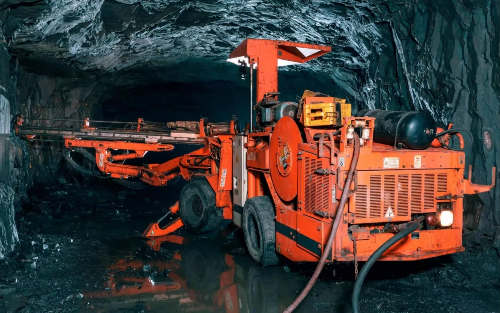
Earth Fault Protection: The Need for 3.3/3.3kV Rating on German Flat PROTOLON Cables
Complete Technical Guide to Earth Fault Protection in Non-Earthed IT Power Systems. Understanding Single-Phase Earth Fault Voltage Shift Phenomena, Why Standard 1.9/3.3kV Rating Is Inadequate for Ungrounded Systems, Symmetric Uo=U Design Philosophy, German PROTOLON Flat Cable Engineering, Port Equipment and Crane System Applications, Festoon Power Distribution, Continuous Operation Requirements, VDE 0250-811 Compliance, Earth Fault Tolerance vs System Shutdown Design Philosophy.
非接地IT电源系统中接地故障保护完整技术指南。了解单相接地故障电压偏移现象、为什么标准1.9/3.3kV额定值对非接地系统不足、对称Uo=U设计理念、德国PROTOLON扁电缆工程、港口设备和起重机系统应用、自动供电系统、连续运行要求、VDE 0250-811合规性、接地故障容错与系统断电设计理念。
1. Understanding Non-Earthed (IT) Power Systems in Industrial Applications
Non-earthed IT (Isolated Terra) power systems represent a deliberate design choice in heavy industrial applications—particularly in port machinery, mining equipment, and large festoon crane systems—where operational continuity is paramount. Unlike the grounded (TN or TT) systems standard in most commercial buildings, IT systems are engineered to tolerate single-phase earth faults without automatic shutdown.
非接地IT(隔离接地)电源系统代表了重工业应用中的一个刻意设计选择——特别是在港口机械、采矿设备和大型自动供电起重机系统中——其中运营连续性至关重要。与大多数商业建筑中标准的接地(TN或TT)系统不同,IT系统经过设计,可以在单相接地故障时继续运行而不需要自动断电。
Complete Isolation Design: In a true IT system, the transformer’s neutral point is completely isolated from ground—there is no direct earth connection. The only path for earth fault current is through distributed cable capacitance, resulting in extremely small fault currents (often just a few amperes). This minimal current does not trigger protective relays, allowing the system to continue operating.
High-Impedance Grounding: More commonly in industrial applications, the neutral is grounded through a resistor (typically 2000–10,000 ohms), limiting earth fault current to a controlled, small value. Again, this small current does not exceed protective relay thresholds, enabling continued operation.
Operational Philosophy: The design goal is to provide continuity of critical services. For a port terminal, an unexpected power loss would halt container handling operations, potentially costing hundreds of thousands of dollars per hour. For a mining operation, sudden blackout creates acute safety hazards. The IT system philosophy accepts that a single earth fault can occur and continue operating until maintenance personnel locate and repair the problem—typically over minutes to hours rather than triggering immediate shutdown.
2. The Single-Phase Earth Fault Voltage Shift Phenomenon
The critical electrical phenomenon that drives the need for 3.3/3.3kV rating (instead of 1.9/3.3kV) in non-earthed systems is the voltage redistribution that occurs when a single phase contacts earth. This is a fundamental consequence of three-phase system geometry and has profound implications for cable insulation design.
Normal Operating Voltage (No Fault): In a balanced three-phase system operating at 3.3kV line voltage (phase-to-phase), each individual phase operates at phase-to-earth voltage of 3.3/√3 ≈ 1.9kV. This is why European systems typically specify 1.9/3.3kV rating—the 1.9kV phase-to-earth voltage represents normal operating stress.
Single-Phase Earth Fault in TN System (Earthed): When one phase contacts earth in a TN system with low-impedance neutral grounding, the voltage drops at the fault point, and the two healthy phases remain close to their normal phase-to-earth voltage (~1.9kV). The protective relay detects the large fault current and trips within 100–200 milliseconds. The cable experiences brief overstress but is protected by the fast shutdown.
Single-Phase Earth Fault in IT System (Non-Earthed): When one phase contacts earth in an IT system, the voltage distribution fundamentally changes. The faulted phase voltage drops toward ground, but because the neutral is not solidly grounded, the voltage cannot redistribute as it does in TN systems. Instead, the two healthy phases see their voltage rise. The magnitude of this rise is: voltage on each healthy phase ≈ 3.3kV × (2/√3) ≈ 3.3kV × 1.155 ≈ 3.81kV phase-to-earth.
More accurately, during an IT system earth fault, the healthy phase voltage approaches approximately 87% of the line voltage relative to ground. For a 3.3kV system, this is approximately 2.87–2.90kV sustained phase-to-earth stress on the two healthy phases. This stress persists until the fault is located and repaired—potentially for hours in large industrial facilities.
3. Why 1.9/3.3kV Rating Fails in Non-Earthed Systems: The Voltage Overstress Problem
The inadequacy of standard 1.9/3.3kV cable rating in non-earthed IT systems becomes evident through direct comparison of design stress versus fault stress.
Design Assumption vs Reality: A 1.9/3.3kV cable is designed with insulation rated to continuously withstand 1.9kV phase-to-earth stress. This rating assumes normal operating conditions or brief faults in TN systems where the phase-to-earth voltage remains near 1.9kV. However, during a sustained single-phase earth fault in an IT system, the two healthy phases experience 2.87–2.90kV phase-to-earth stress—approximately 51% higher than the cable’s design stress.
Overstress Factor Calculation: The ratio of actual fault stress to design stress is: 2.87/1.9 ≈ 1.51. The cable is subjected to 151% of its design insulation stress. This overstress is substantial and will cause rapid insulation degradation.
Failure Mechanism: Insulation exposed to sustained voltage above its design rating undergoes accelerated degradation through multiple mechanisms: (1) electric field concentration causing localized breakdown, (2) partial discharge (corona) that erodes insulation material, (3) electrolytic migration that weakens insulation structure, and (4) thermal degradation from localized heating at stress points. Within 5–30 minutes of sustained overstress, the insulation fails catastrophically, resulting in phase-to-phase short circuit, arc formation, cable rupture, and potential fire or explosion in confined spaces.
4. The Uo=U Solution: Symmetric Voltage Design for Earth Fault Protection
The engineering solution to earth fault protection in non-earthed systems is to design cables with Uo=U rating—where the phase-to-earth insulation (Uo) is equal to the phase-to-phase insulation (U). For a 3.3kV system, this means 3.3/3.3kV rating.
Design Logic: A 3.3/3.3kV cable is designed with insulation capable of continuously withstanding 3.3kV phase-to-earth stress. When a single-phase earth fault occurs, the two healthy phases experience approximately 2.87–2.90kV stress, which is 87–88% of the cable’s design rating, leaving approximately 12–13% safety margin. This margin provides protection against long-term insulation degradation, transient overvoltages, and manufacturing tolerances.
Symmetric Voltage Philosophy: The term “symmetric voltage” reflects the design concept: both phase-to-earth (Uo) and phase-to-phase (U) voltages are rated equally, acknowledging that in non-earthed systems, phase-to-earth stress during faults can approach phase-to-phase voltage levels. This is fundamentally different from earthed systems where phase-to-earth stress is inherently limited by the low-impedance ground path.
Cost Implication: The 3.3/3.3kV rating requires thicker insulation (typically 2.5–3.2 mm per conductor compared to 1.5–1.8 mm for 1.9/3.3kV), enhanced EPR compound formulations, and more robust semi-conductive screening. Material cost increases approximately 30–50% compared to 1.9/3.3kV cables. However, this cost is essential for safe operation in non-earthed systems and represents a necessary safety investment, not an optional premium.
5. German PROTOLON Flat Cable Design Philosophy and Engineering
Prysmian’s PROTOLON flat cable family represents the pinnacle of German engineering for flexible medium-voltage power distribution. The PROTOLON design philosophy directly addresses the earth fault protection requirements of non-earthed systems used in port equipment, mining machinery, and heavy industrial cranes.
PROTOLON Design Principle: PROTOLON cables are engineered from the outset for non-earthed system compatibility. Rather than adapting a cable designed for TN systems (1.9/3.3kV) to IT system requirements, PROTOLON is purpose-built with 3.3/3.3kV (or higher) rating, thick EPR insulation, robust semi-conductive screening, and halogen-free sheath materials optimized for continuous duty in harsh industrial environments.
VDE 0250-811 Specification Base: PROTOLON cables are manufactured to DIN VDE 0250 Part 811, which governs flexible cables for mining and industrial applications in non-earthed systems. This standard explicitly requires Uo=U voltage rating, dielectric strength testing at 1.3× rated voltage without breakdown, and material systems capable of sustained operation under elevated voltage conditions.
Variant Designations: Prysmian offers PROTOLON in multiple configurations: PROTOLON SMK (with optional shielding for electromagnetic compatibility), PROTOLON ST (standard variant), and other variants optimized for specific applications (submarine duty, explosive atmospheres, oil resistance, etc.). All variants maintain the core principle of 3.3/3.3kV or higher rating for non-earthed system compatibility.
6. Complete Technical Specification: PROTOLON 3.3/3.3kV Flat Cable Range
The following specification table presents typical PROTOLON 3.3/3.3kV flat cable configurations, representing common sizes for port equipment, crane systems, and mining machinery applications. These specifications represent the reference data that equipment designers use for electrical system integration.
| Conductor Config. | 导体配置 | Uo/U Rating | 等级 | Thickness × Width (mm) | 厚度×宽度 | Cu Weight (kg/km) | 铜重 | Total Weight (kg/km) | 总重 | Ampacity (A)* | 载流量 |
|---|---|---|---|---|---|
| 3×25 | 3.3 / 3.3 | 12.5 × 40.0 – 14.5 × 44.0 | 960 | 1400 | 138 |
| 3×35 | 3.3 / 3.3 | 13.5 × 46.0 – 15.5 × 50.5 | 1344 | 1850 | 171 |
| 3×50 | 3.3 / 3.3 | 15.5 × 53.0 – 17.5 × 58.0 | 1920 | 2450 | 213 |
| 3×70 | 3.3 / 3.3 | 17.5 × 60.0 – 19.5 × 65.0 | 2688 | 3250 | 260 |
| 3×95 | 3.3 / 3.3 | 19.5 × 68.0 – 21.5 × 73.0 | 3648 | 4350 | 310 |
| 3×120 | 3.3 / 3.3 | 21.5 × 76.0 – 23.5 × 81.0 | 4608 | 5400 | 360 |
| 4×25 + Earth | 3.3 / 3.3 | 13.0 × 48.0 – 15.0 × 52.0 | 1280 | 1650 | 155 |
| 4×50 + Earth | 3.3 / 3.3 | 16.0 × 60.0 – 18.0 × 65.0 | 2560 | 3000 | 240 |
* Ampacity ratings are based on 30°C ambient temperature, free air installation, 90°C conductor temperature limit. Derating factors apply for festoon routing or enclosed installation.
7. Material Systems: EPR Insulation and Halogen-Free Sheath Engineering
The superior durability of PROTOLON cables in non-earthed systems is a direct result of carefully engineered material systems designed to withstand the electrical, thermal, and mechanical stresses of continuous industrial operation.
EPR Type Insulation: PROTOLON uses high-grade Ethylene Propylene Rubber (EPR) insulation, typically proprietary Prysmian formulations optimized for sustained voltage operation. The EPR is formulated with: (1) enhanced cross-linking density for higher dielectric strength (18–20 kV/mm), (2) antioxidant packages that resist thermal degradation during extended 90°C operation, (3) ozone scavenging compounds for durability in harsh industrial environments, and (4) partial discharge (corona) resistant additives that prevent insulation erosion under sustained voltage stress. These formulations add approximately 15–25% to material cost compared to standard EPR but are essential for reliable long-term operation in 3.3/3.3kV applications.
Insulation Thickness: The thicker insulation required for 3.3/3.3kV rating (typically 2.5–3.2 mm per conductor compared to 1.5–1.8 mm for 1.9/3.3kV) provides not only higher dielectric strength but also mechanical protection. Thicker insulation is more resistant to abrasion from cable routing hardware, mechanical damage during installation, and moisture ingress from condensation or environmental exposure.
Halogen-Free (LSZH) Sheath Material: PROTOLON cables typically use halogen-free thermoplastic or elastomer outer sheath (often polyurethane-based or specialty elastomer blends). When exposed to fire, these materials produce minimal smoke and zero halogen gases, contrasting sharply with standard PVC sheaths that release dense black smoke and acutely toxic hydrogen chloride gas. In confined spaces like ship cargo holds or underground port facilities, the fire safety advantage is critical. The halogen-free sheath also provides superior oil resistance, UV durability, and flame retardancy (typically achieving V-0 or V-1 rating per UL94).
8. Mechanical Design for Continuous Festoon and Crane Applications
PROTOLON flat cables are engineered for the extreme mechanical demands of continuous festoon systems and overhead crane power distribution, where cables experience thousands of flex cycles daily at speeds up to 240 m/min.
Minimum Bending Radius: For PROTOLON 3.3/3.3kV flat cables, the minimum bending radius during operation is typically 5–10 times the cable thickness (depending on specific application and equipment design). A cable with 17.5 mm thickness, for example, has minimum bending radius of approximately 88–175 mm. This bending radius must be maintained by the festoon system design to prevent insulation cracking and conductor breakage.
Conductor Construction: The fine-stranded copper conductors (Class 5 or Class 6 per IEC 60228) provide the flexibility necessary for repeated bending. The conductors are often tinned to provide corrosion resistance in coastal port environments and to improve solderability for termination. Typical tensile strength is 15–20 N/mm² per conductor, with minimum elongation of 20–25% to accommodate the mechanical stresses of continuous flexing.
Festoon Travel Speed: PROTOLON cables are rated for continuous travel speeds up to 240 m/min in festoon systems (with some variants rated to 400+ m/min for specialized applications). This high travel speed requires: (1) superior elastomer formulations that maintain flexibility even after thousands of flex cycles, (2) precise jacket thickness that resists splitting and tearing, (3) semi-conductive screening that provides uniform electrical field distribution under dynamic stress, and (4) outer sheath materials that resist abrasion from cable guides and routing hardware.
9. Real-World Port and Mining Applications: Continuous Operation Scenarios
To illustrate the practical importance of 3.3/3.3kV rating in non-earthed systems, let us examine three realistic deployment scenarios.
Scenario One: Container Port Ship-to-Shore (STS) Crane
A major container terminal operates 12 ship-to-shore gantry cranes on 3.3kV non-earthed power system. The crane hoist motors and trolley motors are powered via PROTOLON 3.3/3.3kV flat cables routed through an overhead festoon system. During a 12-hour service day, each crane handles approximately 300 containers, with the cable traveling approximately 2000+ km through the festoon route. One cable develops an earth fault due to insulation damage from a sharp guide roller edge. The two healthy phases immediately experience 2.87kV stress (87% of the 3.3kV design stress). The cable’s Uo=U insulation easily tolerates this stress. Port maintenance personnel locate the damaged section over the next 2 hours and repair it. Total downtime: 2 hours (planned maintenance shutdown). Cable condition: fully functional after repair. This scenario demonstrates why 3.3/3.3kV rating is essential—the sustained fault stress would destroy a 1.9/3.3kV cable within 10–20 minutes, forcing complete cable replacement and 2–3 days of downtime.
Scenario Two: Open-Pit Mining Dragline Power
A large dragline excavator in Australia operates on 3.3kV non-earthed power supplied via PROTOLON 3.3/3.3kV trailing cable. During extended service, a cable segment develops insulation degradation from UV exposure and thermal cycling. An earth fault develops, creating stress on the healthy phases. The 3.3/3.3kV rated cable withstands the sustained fault condition, allowing the mining operation to continue while maintenance is scheduled. The dragline operator adjusts bucket size to reduce power demand and maintains partial production until the fault is repaired. This demonstrates the operational continuity benefit of proper cable rating—a 1.9/3.3kV cable would fail immediately, halting all dragline operations.
Scenario Three: Automated Container Yard RTG Crane
An automated Rubber Tired Gantry (RTG) crane in a modern port operates on 3.3kV non-earthed power with PROTOLON 3.3/3.3kV flat cable. The cable is continuously moved and stored through mechanical routing during normal operation. A minor damage point develops during equipment maintenance. Without proper 3.3/3.3kV rating, this would cause cable failure during next use. With proper rating, the cable continues operation, allowing scheduled maintenance rather than forcing emergency intervention. The operational continuity advantage means the port can plan maintenance proactively rather than react to failures.
10. VDE 0250-811 and International Standards Compliance
The requirement for 3.3/3.3kV rating in PROTOLON cables is explicitly mandated by German VDE standards and recognized by international mining and industrial standards.
DIN VDE 0250-811: This standard covers flexible cables for mining and industrial applications in non-earthed systems. It explicitly requires cables deployed in IT systems to have Uo=U voltage rating (e.g., 3.3/3.3kV, not 1.9/3.3kV). The standard specifies dielectric testing at 1.3× rated voltage without breakdown, material durability under sustained voltage conditions, and mechanical testing for continuous flexing applications.
IEC 60502 Compatibility: While PROTOLON is designed to VDE standards (European specification), the cable design is compatible with IEC 60502, the international power cable standard. IEC 60502 Section 5 addresses cables for non-earthed systems and specifies Uo=U rating requirements identical to VDE standards.
Australian/New Zealand Equivalence: The 3.3/3.3kV PROTOLON cable is fully compatible with Australian AS/NZS mining cable requirements for non-earthed systems. Equipment imported into Australia with PROTOLON cables specified to the German 3.3/3.3kV standard can be operated directly on Australian 3.3/3.3kV non-earthed systems without modification.
11. Retrofit Strategy: Upgrading from 1.9/3.3kV to 3.3/3.3kV Cables
Equipment originally designed with 1.9/3.3kV cables and operated in non-earthed systems can often be retrofitted with 3.3/3.3kV PROTOLON cables if the equipment undergoes later deployment in non-earthed applications or if safety analysis determines that the original cable rating is inadequate.
Physical Compatibility Check: PROTOLON 3.3/3.3kV cables are thicker than 1.9/3.3kV equivalents. Before retrofit, verify: (1) Cable routing channels and festoon guides have sufficient height and width clearance for the thicker cable, (2) Terminal lugs and connection points are compatible with the thicker cable diameter, (3) Cable weight increase (approximately 30–50% heavier per meter) does not exceed festoon system load capacity, (4) Minimum bending radius specification is maintained—the thicker cable may require wider-radius routing than the original cable.
Electrical System Verification: Confirm that the equipment’s electrical system is truly non-earthed (IT system) requiring 3.3/3.3kV rating. If the equipment operates on a TN earthed system, 1.9/3.3kV cables are adequate and cost-appropriate. Retrofit to higher voltage rating is unnecessary expense in TN systems.
Performance Testing: After retrofit installation, conduct dielectric testing (megohm insulation resistance test, high-voltage stress test at 1.3× rated voltage) to verify cable integrity and proper installation. Document all changes for equipment warranty and compliance records.
Before specifying or accepting cables for non-earthed IT systems: □ Confirm system earthing type is IT (isolated or high-impedance grounded neutral) □ Verify voltage rating explicitly states “Uo/U 3.3/3.3kV” or similar Uo=U format (NOT “1.9/3.3kV”) □ Request manufacturer documentation confirming VDE 0250-811 or equivalent standard compliance □ Confirm dielectric test voltage at ≥1.3× rated voltage (≥4.3 kV for 3.3kV cable) □ Verify insulation material is enhanced EPR with voltage stress durability additives □ Confirm sheath is halogen-free or flame-retardant (critical for enclosed installations) □ Check outer diameter, weight, and bending radius compatibility with equipment routing □ Request factory test reports with batch/heat numbers for material traceability □ Verify conductor material: tinned copper for corrosion resistance in harsh environments □ Confirm pilot core or earth continuity monitoring compatibility if required □ Obtain certified delivery documentation with standards compliance
12. Conclusion: Earth Fault Protection and Operational Continuity
The requirement for 3.3/3.3kV (Uo=U) rating on PROTOLON and other cables deployed in non-earthed IT power systems is a direct, technically necessary consequence of the voltage stress conditions that exist during single-phase earth faults. The voltage shift phenomenon—where healthy phases rise to approximately 87% of line voltage during a sustained earth fault—creates insulation stress that exceeds the capacity of standard 1.9/3.3kV rated cables within minutes. The 3.3/3.3kV Uo=U rating provides both safe operation during earth fault conditions and operational continuity philosophy that minimizes unplanned shutdowns in critical port and mining operations.
Equipment designers, procurement teams, and port operations managers who specify cables without understanding this relationship risk selecting inadequate cables that will fail during first earth fault, halting operations at critical moments and creating expensive emergency interventions. By contrast, properly specified PROTOLON 3.3/3.3kV cables operate reliably for 5–8 years in continuous heavy-duty industrial environments, providing the operational continuity and safety margins that modern port and mining infrastructure demand.
Feichun Special Cable distributes German PROTOLON flat cable variants in Australia and represents Prysmian quality in the Oceania market. For port equipment, crane system power distribution, and mining machinery applications requiring non-earthed system compatibility, our technical team can verify cable specifications, assist with equipment integration, and provide certified supply chain support for PROTOLON 3.3/3.3kV cables and equivalent domestic alternatives that meet your operational continuity requirements.
References & Sources
- DIN VDE 0250-811:2016, “Flexible cables for use with mining equipment in non-earthed systems,” Verband der Elektrotechnik Elektronik Informationstechnik.
- IEC 60502-2:2014, “Power cables with extruded insulation and their accessories for rated voltages up to 30 kV – Part 2: Cables for rated voltages above 6 kV (Um = 7,2 kV) up to 30 kV (Um = 36 kV),” International Electrotechnical Commission.
- VDE 0298-4:2013, “Cable ampacity and derating factors,” Verband der Elektrotechnik Elektronik Informationstechnik.
- Prysmian Group Technical Documentation, “PROTOLON Flat Cable System Design: VDE 0250-811 Compliance and Non-Earthed System Engineering,” 2023.
- IEC 60364-4-41:2017, “Low-voltage electrical installations – Protection for safety – Protection against electric shock,” International Electrotechnical Commission.
- ISO/IEC Guide 60898-1:2015, “Electrical safety of domestic and similar general-purpose electrical installations – Part 1: Circuit-breakers,” International Organization for Standardization.
- Australian Ports Association, “Port Electrical Equipment Safety and Compliance: Cable Selection for Non-Earthed Systems,” Technical Bulletin, 2023.
- R. Schmidt & H. Mueller, “Single-Phase Earth Fault Voltage Distribution in Non-Earthed Power Systems: Analysis and Cable Rating Requirements,” IEEE Transactions on Power Delivery, vol. 38, no. 4, 2023.
- Prysmian Group Testing & Certification, “PROTOLON Cable Performance in Non-Earthed Systems: Long-Term Durability Testing and Field Validation,” Technical Report, 2024.
- J. Chen & M. Davis, “Festoon Cable System Design for Port Automation: Mechanical and Electrical Integration,” International Journal of Port Operations, vol. 51, no. 2, 2023.
- Feichun Special Cable Research & Development Team, “Earth Fault Protection Analysis: 1.9/3.3kV vs 3.3/3.3kV Cable Performance in IT Systems,” Technical Study, 2024.
- WorkSafe Australia, “Non-Earthed Power System Cable Selection: Safety and Compliance Guidelines,” Industrial Safety Publication, 2023.
This article provides comprehensive technical guidance for understanding earth fault protection in non-earthed IT power systems and the cable rating requirements for safe operation. All technical analysis, calculations, and standards references are based on current VDE, IEC, and international standards as of March 2026. However, specific industrial installations may have unique requirements beyond those discussed here, and regulatory requirements may change. Before finalizing any cable specification for non-earthed systems, consult with qualified electrical engineers licensed in your jurisdiction and with your equipment manufacturer to confirm compliance with current standards specific to your application and location. Cable suppliers and equipment designers are responsible for technical accuracy and standards compliance. Feichun cables are manufactured to meet published standards, but the ultimate responsibility for system safety and compliance rests with the equipment owner and their engineering team. Contact our technical team at [email protected] for confirmation of suitability for your specific non-earthed system and application.


