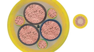
CXP-6 PUR Round Cable for Demanding Industrial Applications

Understanding the 11YMSL11Y & 11YMSLC11Y Cable: CXP-6 PUR Round Cable for Demanding Industrial Applications
The 11YMSL11Y and 11YMSLC11Y cables, also known as CXP-6 PUR round cables, represent a pinnacle of engineering excellence in the field of industrial power transmission. These highly flexible cables are specifically designed for the most demanding applications including energy guiding chains, festoon trolley systems, container cranes, and heavy industrial machinery where reliability and durability are paramount.
1. What is the 11YMSL11Y/11YMSLC11Y Cable?
The 11YMSL11Y and 11YMSLC11Y cables are high-performance polyurethane (PUR) sheathed round cables classified as Category 6 highly flexible cables according to DIN VDE 0295. These cables are engineered with advanced materials and construction techniques to withstand the extreme mechanical stresses encountered in mobile industrial applications.
Cable Designation Explained
- 11Y – Thermoplastic polymer insulation (halogen-free)
- MSL – Round cable designation
- C (in 11YMSLC11Y) – Braided copper wire shield (approximately 85% coverage)
- 11Y – Polyurethane (PUR) outer sheath (halogen-free)
The cable family includes control cables, power cables (1-core, 4-core, 5-core, and 7-core), data cables, and specialized bus cables including CAN BUS, DeviceNet, and Profibus variants. The screened versions (11YMSLC11Y) provide enhanced electromagnetic compatibility (EMC) for applications requiring signal integrity in electrically noisy environments.
2. Purpose and Applications
Primary Application: Energy Guiding Chains
Energy guiding chains (also known as cable carriers or drag chains) are mechanical systems that guide and protect cables and hoses during repetitive motion. The 11YMSL11Y/11YMSLC11Y cables excel in these applications due to their exceptional flexibility, resistance to mechanical stress, and long service life even under continuous flexing conditions.
Secondary Application: Festoon Trolley Systems
Festoon systems deliver power and control signals to moving equipment such as overhead cranes and gantry systems. These cables are ideal for festoon applications because of their compact bundle structure, wear-resistant PUR sheath, and ability to maintain electrical performance during constant motion.
Typical Industrial Applications
Brand: LifeLine
The 11YMSL11Y/11YMSLC11Y cable series is marketed under the LifeLine brand, indicating cables designed for applications involving medium to high dynamic travel speeds where frequent and continuous flexing is expected throughout the cable’s operational lifetime.
3. Key Characteristics and Features
Exceptional Flexibility
Category 6 highly flexible conductor construction (DIN VDE 0295) enables tight bending radii of only 7.5 times the cable diameter, essential for compact energy chain installations.
Durable PUR Outer Sheath
Polyurethane sheathing provides outstanding wear resistance, low friction properties, and exceptional mechanical strength for demanding mobile applications.
Halogen-Free & Flame Retardant
Self-extinguishing and flame retardant according to DIN VDE 0482 part 265-2-1 and IEC 60332-1, with halogen-free materials reducing toxic emissions in fire scenarios.
Wide Temperature Range
Operational flexibility from -30°C to +80°C during motion, and -35°C to +85°C when fixed, accommodating diverse environmental conditions.
High Voltage Capacity
Rated voltage of 0.6/1 kV (600/1000V) for conductors 1.5mm² and above, with 300/500V for smaller conductors and 300V for bus cables.
Anti-Corkscrew Design
Twist-free stranding with reverse twist construction prevents cable spiraling and ensures stable performance during repetitive motion cycles.
Environmental Resistance
Resistant to ozone, UV radiation, oils, atmospheric corrosion, and humidity, suitable for both indoor and outdoor installations.
International Certifications
UL/CSA listed and DESINA compliant, meeting stringent international safety and performance standards.
Compact Bundle Structure
The cable’s small size is achieved through a compact bundle structure that reduces overall diameter while maintaining electrical and mechanical performance. This design minimizes space requirements in energy chains and festoon systems where multiple cables must be routed efficiently.
4. Material Structure and Design
Conductor Construction
The cable utilizes bare electrolytic copper conductors configured in a highly flexible Category 6 construction according to DIN VDE 0295 and IEC 60228. This fine-strand conductor design provides superior flexibility and fatigue resistance compared to standard conductor classes.
| Component | Material | Purpose |
|---|---|---|
| Conductor | Bare electrolytic copper, Class 6 | Electrical transmission with maximum flexibility |
| Core Insulation | TPE-basis thermoplastic compound (halogen-free) | Electrical insulation and thermal stability |
| Inner Protective Sheath | Thermoplastic polymer | Mechanical protection and layer bonding |
| Shield (C version only) | Braided bare copper wires (85% coverage) | EMI/RFI protection and grounding |
| Outer Sheath | Polyurethane (PUR) with sliding properties | Abrasion resistance, flexibility, environmental protection |
Stranding Technology
The cable employs advanced stranding techniques optimized for the number of conductors:
- Up to 7 conductors: Layer stranding with reverse twist and short lay length
- Up to 12 conductors: Bundle stranding with reverse twist and short lay length
This specialized stranding design is critical for preventing corkscrew effects (cable spiraling) during repetitive bending cycles, which can lead to premature failure in energy chain applications.
Color Coding
Conductor identification follows a systematic approach:
- Black cores with white numbering for power and control cables
- Green/yellow conductor for protective earth (when applicable)
- Outer sheath color varies by cable type:
- Black: Data cables, Profibus, DeviceNet, and CAN BUS
- Purple: Screened control cables up to 1mm²
- Grey: Screened control and power cables from 1.5mm²
- Orange: Standard identification color
5. Standards Compliance and Certifications
International Standards
The 11YMSL11Y/11YMSLC11Y cable series is manufactured in accordance with multiple international standards, ensuring global applicability and regulatory compliance:
Key Standard Requirements
| Standard | Scope | Compliance Aspect |
|---|---|---|
| DIN VDE 0250 | Cables, wires and flexible cords for power installation | General construction and performance requirements |
| DIN VDE 0295 / IEC 60228 | Conductors of cables | Category 6 highly flexible conductor construction |
| DIN VDE 0298 Part 4 | Current-carrying capacity | Ampacity calculations and derating factors |
| DIN VDE 0482 / IEC 60332-1 | Fire performance | Flame retardant and self-extinguishing properties |
| UL/CSA | North American safety standards | Electrical safety and fire performance for US/Canada |
| DESINA | German crane and material handling standards | Specific requirements for crane applications |
Environmental and Safety Certifications
- Halogen-Free: Contains no halogens (fluorine, chlorine, bromine, iodine), reducing toxic and corrosive emissions in fire
- CFC-Free: Manufactured without chlorofluorocarbons, supporting environmental protection
- LBS-Free / Silicone-Free: Prevents contamination in sensitive manufacturing environments
- RoHS Compliant: Meets restrictions on hazardous substances
6. Safety Thresholds and Technical Parameters
Electrical Safety Parameters
| Parameter | Value | Notes |
|---|---|---|
| Rated Voltage (Uo/U) | 0.6/1 kV (600/1000V) | For conductors ≥1.5mm² |
| Rated Voltage (Uo/U) | 300/500V | For conductors ≤1mm² |
| Bus Cable Voltage (U) | 300V | CAN BUS, Profibus, DeviceNet |
| Max AC Operating Voltage | 700/1200V | Continuous operation limit |
| Max DC Operating Voltage | 900/1800V | Continuous operation limit |
| AC Test Voltage | 2.5 kV | Type testing requirement |
Thermal Safety Thresholds
| Condition | Temperature Range | Application |
|---|---|---|
| Flexing Operation | -30°C to +80°C | Moving applications (energy chains, festoons) |
| Fixed Installation | -35°C to +85°C | Stationary cable runs |
| Maximum Conductor Temperature | 90°C | Normal continuous operation |
| Short-Circuit Temperature | 200°C | Maximum 5 seconds duration |
Critical Temperature Warning
Exceeding the maximum conductor temperature of 90°C can lead to insulation degradation and premature cable failure. Proper ampacity calculations must be performed considering ambient temperature, installation method, and duty cycle. The short-circuit temperature limit of 200°C is a safety threshold that must not be exceeded to prevent permanent cable damage.
Mechanical Safety Parameters
| Parameter | Specification | Significance |
|---|---|---|
| Minimum Bending Radius | 7.5 × cable diameter | For moving applications with free movement |
| Travel Speed | Up to 250 m/min (standard) | >250 m/min available on request |
| Tensile Load Capacity | 15 N/mm² | During operation for moving cables (DIN VDE 0298-3) |
| Permitted Tensile Load | Varies by cable type | See specific product tables (range: 15N to 2250N) |
Current Carrying Capacity (Ampacity)
The ampacity values are calculated based on:
- Ambient temperature of 30°C
- Cables laid on an even, flat support
- 100% duty cycle (continuous operation)
- Single cable installation
Ampacity Derating Factors
The published ampacity values must be adjusted for actual operating conditions:
- Ambient Temperature: Higher ambient temperatures reduce ampacity
- Grouping: Multiple cables in close proximity require derating
- Installation Method: Cable trays, conduits, or energy chains affect heat dissipation
- Duty Cycle: Intermittent operation may allow higher loads
Refer to DIN VDE 0298 Part 4 for comprehensive derating calculations.
7. Precautions for Use and Installation
Installation Guidelines
⚠️ Critical Installation Requirements
- Never exceed minimum bending radius: Bending below 7.5 × cable diameter causes conductor damage and insulation stress
- Avoid twisting: Cable rotation during installation can compromise the anti-corkscrew design
- Proper tensile load management: Do not exceed the specified tensile load for the cable cross-section
- Correct termination: Use appropriate cable glands and strain relief to prevent pullout forces on connections
Energy Chain Installation Best Practices
- Chain Selection: Choose energy chain dimensions allowing minimum 10% free space after cable installation
- Cable Layout: Arrange cables side-by-side rather than stacking when possible to improve heat dissipation
- Separation: Use dividers to prevent cable-to-cable abrasion in multi-cable installations
- Fixed End: Secure cables at the fixed end with proper strain relief devices
- Moving End: Allow adequate service loop at the moving end for smooth operation
- Chain Speed: Ensure travel speed is within cable specifications (up to 250 m/min standard)
Festoon System Installation
- Trolley Spacing: Maintain proper trolley spacing to support cable weight and prevent excessive sagging
- Track Alignment: Ensure festoon track is properly aligned and level to prevent binding
- Cable Support: Use appropriate cable hangers or clamps designed for the cable diameter
- End Connections: Provide adequate strain relief at power and equipment connection points
- Weather Protection: For outdoor installations, ensure proper sealing of junction boxes and connections
Environmental Considerations
- Temperature Monitoring: Verify ambient temperature remains within -30°C to +80°C range for moving applications
- Chemical Exposure: While oil-resistant, avoid prolonged exposure to aggressive chemicals not covered in specifications
- UV Protection: Although UV-resistant, provide additional protection for extreme solar exposure when possible
- Moisture: Ensure proper sealing of connections; cable sheath is moisture-resistant but not waterproof at terminations
Electrical Safety Precautions
⚡ Electrical Safety Requirements
- De-energize circuits before installation or maintenance work
- Follow local electrical codes and lockout/tagout procedures
- Verify proper grounding of screened cable shields (11YMSLC11Y versions)
- Use appropriate personal protective equipment (PPE)
- Ensure connections are rated for the cable’s voltage and current capacity
- Implement proper overcurrent protection devices sized according to cable ampacity
Handling and Storage
- Storage Temperature: Store in dry location at temperatures between -5°C and +40°C
- Coil Storage: Store cables in original packaging on reels or in coils to maintain shape
- Avoid Sharp Bends: Do not create tight bends during handling that could damage conductors
- Protect from Damage: Keep cables away from sharp edges, heavy objects, and mechanical impacts
- Shelf Life: PUR materials have excellent aging characteristics; use within 2 years for optimal performance
8. Common Problems and Solutions
Problem 1: Premature Cable Failure in Energy Chains
Symptoms: Cable fails before expected service life, visible conductor breakage, insulation cracking
Causes:
- Bending radius smaller than 7.5 × cable diameter
- Energy chain undersized for cable bundle
- Excessive travel speed or acceleration
- Improper cable selection for duty cycle
Solutions:
- Verify energy chain radius meets minimum bending requirements
- Upgrade to larger energy chain if space is inadequate
- Reduce travel speed or acceleration if exceeding 250 m/min
- Consider higher specification cable for extreme duty cycles
Problem 2: Cable Corkscrewing or Twisting
Symptoms: Cable develops spiral twist, binding in energy chain, uneven wear
Causes:
- Incorrect cable installation with pre-twist
- Improper fixed-end mounting allowing rotation
- Energy chain misalignment
Solutions:
- Reinstall cable ensuring no twist during installation
- Secure both fixed and moving ends to prevent rotation
- Verify energy chain track alignment
- The cable’s reverse-twist stranding design should prevent corkscrewing when properly installed
Problem 3: Excessive Heat Generation
Symptoms: Cable jacket feels excessively warm, insulation softening, reduced cable life
Causes:
- Operating current exceeds ampacity rating
- Inadequate heat dissipation in cable bundle
- High ambient temperature beyond specifications
- Poor electrical connections creating resistance
Solutions:
- Verify actual load current vs. published ampacity tables
- Apply derating factors for ambient temperature and grouping
- Improve cable spacing for better heat dissipation
- Inspect and remake any poor connections
- Consider larger conductor size if operating at capacity limits
Problem 4: Electromagnetic Interference (EMI) in Data Cables
Symptoms: Signal errors, communication failures, erratic control behavior
Causes:
- Using unscreened cable in electrically noisy environment
- Improper shield grounding on screened cables
- Power and data cables too closely bundled
Solutions:
- Upgrade to 11YMSLC11Y screened version for data/control applications
- Ensure shield is properly grounded at one end (typically at panel/controller)
- Maintain separation between power and signal cables
- Use cable dividers in energy chains to segregate power and data cables
Problem 5: Festoon System Cable Stack-up
Symptoms: Cable accumulates at end of travel, restricts crane movement, causes cable damage
Causes:
- Insufficient trolley spacing
- Festoon system length inadequate for travel distance
- Cable too stiff for application
Solutions:
- Recalculate and adjust trolley spacing based on cable weight and stiffness
- Add additional festoon sections if travel distance requires
- Verify cable selection is appropriate for festoon application (11YMSL11Y series is designed for festoon use)
- Consider alternative electrification method if festoon limitations persist
Problem 6: Abrasion and Wear on Cable Jacket
Symptoms: Visible wear marks, jacket thinning, exposed insulation
Causes:
- Cable rubbing against energy chain walls or other cables
- Contamination with abrasive particles
- Sharp edges in installation pathway
Solutions:
- Ensure adequate clearance in energy chain (minimum 10% free space)
- Clean energy chain tracks regularly to remove debris
- Use cable separators to prevent cable-to-cable contact
- Inspect for and eliminate sharp edges in cable pathway
- The PUR sheath is designed for wear resistance, but mechanical protection is still essential
Preventive Maintenance Schedule
| Interval | Inspection Items | Action |
|---|---|---|
| Weekly | Visual inspection of cable condition | Check for visible damage, wear, or unusual conditions |
| Monthly | Detailed cable inspection | Examine jacket condition, connection tightness, signs of overheating |
| Quarterly | Energy chain/festoon system inspection | Check track alignment, trolley condition, cable routing |
| Semi-Annually | Electrical testing | Insulation resistance testing, continuity checks |
| Annually | Comprehensive system evaluation | Full electrical and mechanical assessment, thermal imaging if available |
9. Conclusion
The 11YMSL11Y and 11YMSLC11Y Cable (CXP-6 PUR round cable) represents a sophisticated solution for demanding industrial applications requiring high flexibility, durability, and reliability. Manufactured by Anhui Feichun Special Cable Co., Ltd., these cables incorporate advanced materials and engineering principles to meet the stringent requirements of energy guiding chains, festoon systems, and mobile crane applications.
Key Takeaways
- Exceptional Flexibility: Category 6 conductor design enables 7.5× diameter bending radius for compact installations
- Comprehensive Standards Compliance: DIN VDE, IEC, UL/CSA, and DESINA certified for global applications
- Superior Environmental Resistance: Halogen-free PUR construction withstands oil, UV, temperature extremes, and atmospheric corrosion
- Wide Application Range: Available in control, power, data, and bus cable configurations for diverse industrial needs
- Long Service Life: Anti-corkscrew design and durable construction minimize maintenance and replacement costs
When properly selected, installed, and maintained according to the guidelines outlined in this article, these cables provide reliable performance in the most challenging industrial environments. The comprehensive technical specifications, safety parameters, and problem-solving guidance ensure optimal cable performance throughout its operational lifetime.
For applications involving medium to high dynamic travel speeds, frequent flexing cycles, halogen-free requirements, and operating temperatures up to 80°C, the 11YMSL11Y/11YMSLC11Y cable series offers an ideal balance of performance, safety, and cost-effectiveness.
Contact Anhui Feichun Special Cable Co., Ltd.
For technical inquiries, custom cable solutions, or to place an order, contact our international sales team:
Email: [email protected]
Phone: +86 13855123218
References and Further Reading
- DIN VDE 0250 – Cables, wires and flexible cords for power installations
- DIN VDE 0295 / IEC 60228 – Conductors of cables and cords
- DIN VDE 0298 – Use of cables and flexible cords in power installations
- IEC 60332-1 – Tests on electric cables under fire conditions
- Technomax ME. (December 2024). “What Is A Festoon Cable System? Types And Benefits.” Link
- Grand Ocean Marine. (June 2024). “Exploring Festoon Cable Specifications: An In-Depth Examination.” Link
- Mazzella Companies. (March 2023). “Crane Electrification: Conductor Bars vs. Cable Festoon vs. Cable Reel.” Link
- Eland Cables. “DIN VDE Cable Standards.” Link
- CED Engineering. “Overview of Electric Overhead Traveling (EOT) Cranes.” Link