
AC 600V Unshielded Festoon System Flexible Cable, JIS C 3327 Compliant, −40°C to +90°C Operating Range, Oil-Resistant, Flame-Retardant — The Widest Configuration Range in the WALSTOON® Family: Single-Core Power Cables from 0.75 mm² to 250 mm², Multi-Core Control Cables from 2 to 30 Cores, for Port Gantry Cranes, Ship Unloaders, Cable Chain Systems, and General Industrial Festoon Applications
The Foundation of Every Crane Festoon System: Heavy-Duty Single-Conductor Cables (up to 250 mm²) for High-Current Trolley Drives and Hoist Motors, Multi-Core Configurations (2–30 Cores) for Discrete Control, Relay Logic, and PLC I/O Wiring, Cross-Linked Elastomer Insulation and Chloroprene Rubber Sheath for Oil, Ozone, UV, Abrasion, and Flame Resistance, Class 5 Flexible Stranding for Maximum Flex Life in Dynamic Festoon and Cable Chain Applications
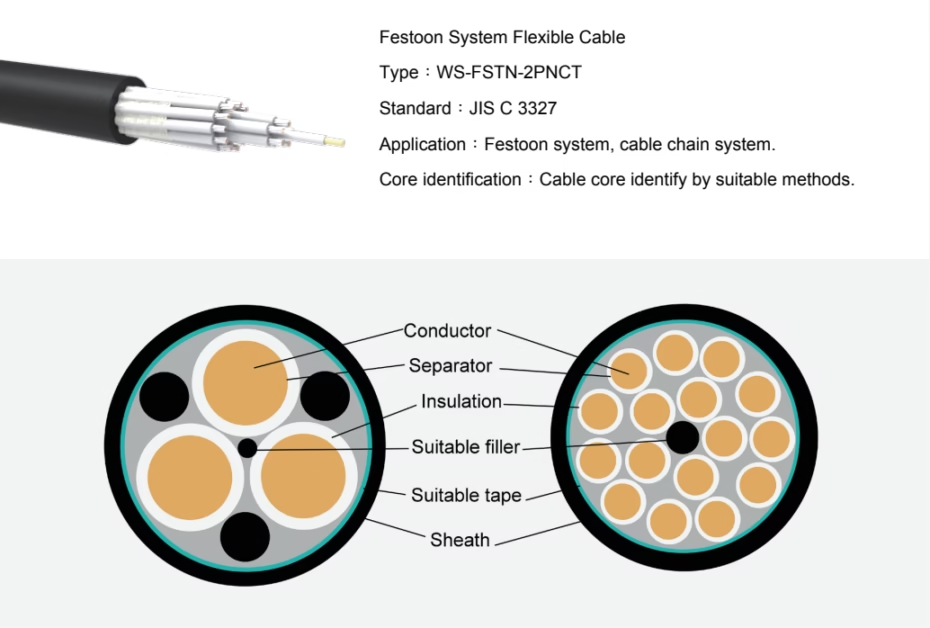
WALSTOON® WS-FSTN-2PNCT Festoon System Flexible Cable
AC 600V Unshielded Festoon System Flexible Cable, JIS C 3327 Compliant, −40°C to +90°C Operating Range, Oil-Resistant, Flame-Retardant — The Widest Configuration Range in the WALSTOON® Family: Single-Core Power Cables from 0.75 mm² to 250 mm², Multi-Core Control Cables from 2 to 30 Cores, for Port Gantry Cranes, Ship Unloaders, Cable Chain Systems, and General Industrial Festoon Applications
The Foundation of Every Crane Festoon System: Heavy-Duty Single-Conductor Cables (up to 250 mm²) for High-Current Trolley Drives and Hoist Motors, Multi-Core Configurations (2–30 Cores) for Discrete Control, Relay Logic, and PLC I/O Wiring, Cross-Linked Elastomer Insulation and Chloroprene Rubber Sheath for Oil, Ozone, UV, Abrasion, and Flame Resistance, Class 5 Flexible Stranding for Maximum Flex Life in Dynamic Festoon and Cable Chain Applications
Introduction: The Workhorse Festoon Cable
The WALSTOON® WS-FSTN-2PNCT is the foundation cable of the WALSTOON festoon system product family — a high-performance, unshielded, rubber-insulated flexible cable engineered for the demanding mechanical and environmental conditions of port gantry cranes, ship unloaders, cable chain systems, and industrial overhead cranes. With the widest configuration range in the WALSTOON product line — from single-conductor 250 mm² power cables capable of carrying hundreds of amperes to compact 30-core × 0.75 mm² multi-circuit control cables — the WS-FSTN-2PNCT addresses every power distribution and discrete control requirement on a crane festoon system.
The WS-FSTN-2PNCT is designed for circuits that do not require electromagnetic shielding: high-current trolley drive power supply, hoist and travel motor feeder cables, main power distribution, discrete relay and contactor control circuits, limit switch wiring, indicator lamp circuits, and general-purpose interconnection. For circuits requiring EMI protection (analogue sensor signals, digital fieldbus communication, VFD encoder feedback), the shielded variants — WS-FSTN-2PNCT-SB (copper shield braid) and WS-FSTN-2PNCT-PSB (Kevlar® reinforced + shield braid) — are available as companion products within the same WALSTOON® family, sharing identical temperature ratings, environmental resistance, and mechanical characteristics for full festoon system compatibility.
The cable is manufactured to JIS C 3327 (Japanese Industrial Standard for rubber-insulated cabtyre cables), with cross-linked elastomer insulation rated to 90°C continuous and a chloroprene rubber (CR) outer sheath providing comprehensive resistance to oil, ozone, UV radiation, abrasion, and flame. The −40°C to +90°C ambient temperature range covers all global port environments from arctic terminals to tropical equatorial ports.
Festoon cables on port cranes are safety-critical components. Cable failure during crane operation can result in loss of crane control, uncontrolled load release, collision damage, and risk to human life. The WS-FSTN-2PNCT cable must be installed, supported, and maintained in strict accordance with the crane manufacturer’s festoon system specifications and local port authority safety regulations. For single-conductor cables carrying high currents (80 mm² and above), ensure terminations are rated for the full conductor ampacity and torqued to manufacturer specifications. Under-torqued terminations are a fire hazard.
Technical Specifications: JIS C 3327 Breakdown
| Parameter | Specification |
|---|---|
| Product Designation | WS-FSTN-2PNCT (Festoon, 2PNCT type, Unshielded) |
| Standard Compliance | JIS C 3327. Construction verified per JIS C 3005. |
| Rated Voltage | AC 600V |
| Test Voltage | AC 3,000V / 1 minute |
| Rated Temperature | 90°C (maximum continuous conductor temperature) |
| Ambient Temperature Range | −40°C to +90°C |
| Minimum Bending Radius | 6 × OD |
| Shielding | None (unshielded). For shielded variants, see WS-FSTN-2PNCT-SB and WS-FSTN-2PNCT-PSB. |
| Flame Retardancy | JIS C 3005 |
| Oil Resistance | JIS C 3005 |
| Abrasion Resistance | JIS C 3327 Table 6.12 |
| Weather Resistance | Resistant to ozone, UV radiation, and moisture. |
| Core Identification | Cores identified by suitable methods per JIS standard. |
| Available Configurations | 1-core: 8–250 mm². 2-core: 0.75–100 mm². 3-core: 0.75–150 mm². 4-core: 0.75–150 mm². 5-core: 0.75–38 mm². 6-core: 0.75–22 mm². 7–30 core: 0.75–3.5 mm². |
Cable Construction: Layer-by-Layer Analysis
| Layer | Material | Function |
|---|---|---|
| Conductor | Annealed copper, Class 5 flexible stranding | Electrical power and signal transmission. Fine-stranded for maximum flex life. Available from 0.75 mm² (signal) to 250 mm² (high-power). |
| Insulation | Cross-linked elastomer, 90°C rated | Primary electrical insulation. Thickness scaled with conductor size: 0.8 mm for ≤3.5 mm², 1.0 mm for 5.5–14 mm², 1.2 mm for 22–38 mm², 1.5 mm for 50–60 mm², 2.0 mm for 80–150 mm², 2.5 mm for 200–250 mm². |
| Core Assembly | Cores with suitable fillers | Multi-core configurations bundled with extruded fillers for circular cross-section and mechanical stability during bending. |
| Outer Sheath | Special chloroprene rubber (CR) compound | Mechanical protection. Resistant to oil, ozone, UV, abrasion, and flame per JIS C 3327. Thickness scaled with cable diameter. |
The WS-FSTN-2PNCT is an unshielded cable — it does not include a metallic braid or foil shield layer. This makes the cable lighter, more flexible, and less expensive than the shielded variants (SB and PSB), making it the optimal choice for power distribution and discrete control circuits where electromagnetic shielding is not required. The absence of a metallic shield also eliminates the need for shield grounding at termination points, simplifying installation.
Unlike the shielded variants (which use a uniform 0.8 mm insulation across all sizes), the WS-FSTN-2PNCT’s insulation thickness increases with conductor size — from 0.8 mm for small conductors (≤3.5 mm²) to 2.5 mm for the largest conductors (200–250 mm²). This ensures adequate dielectric strength at higher operating currents and provides mechanical protection proportional to the cable’s physical size and the forces it experiences during handling and installation.
Dimensional & Electrical Data — 1-Core (8–250 mm²)
| Size (mm²) | Cond. Ø (mm) | Insulation (mm) | Sheath (mm) | OD (mm) | Mass (kg/km) | Max. R 20°C (Ω/km) | Min. IR 20°C (MΩ·km) |
|---|---|---|---|---|---|---|---|
| 8 | 3.7 | 1.0 | 1.7 | 9.2 | 150 | 2.45 | 400 |
| 14 | 4.9 | 1.0 | 1.8 | 11.0 | 220 | 1.39 | 300 |
| 22 | 7.0 | 1.2 | 1.9 | 13.5 | 340 | 0.892 | 300 |
| 30 | 8.1 | 1.2 | 2.0 | 14.5 | 425 | 0.661 | 300 |
| 38 | 9.1 | 1.2 | 2.1 | 15.5 | 515 | 0.525 | 200 |
| 50 | 10.4 | 1.5 | 2.2 | 18.0 | 660 | 0.411 | 200 |
| 60 | 11.6 | 1.5 | 2.3 | 19.0 | 790 | 0.329 | 200 |
| 80 | 13.5 | 2.0 | 2.5 | 22.0 | 1,080 | 0.243 | 200 |
| 100 | 15.2 | 2.0 | 2.6 | 24.0 | 1,310 | 0.193 | 200 |
| 125 | 16.8 | 2.0 | 2.6 | 26.0 | 1,550 | 0.156 | 200 |
| 150 | 18.7 | 2.0 | 2.7 | 27.0 | 1,760 | 0.136 | 200 |
| 200 | 21.2 | 2.5 | 3.0 | 32.0 | 2,410 | 0.0993 | 200 |
| 250 | 23.6 | 2.5 | 3.2 | 35.0 | 2,920 | 0.0803 | 200 |
1-core cables in the 50–250 mm² range are used for high-current trolley drive and hoist motor power supply on STS container cranes and ship unloaders, where three or four single-conductor cables (L1, L2, L3, and optionally PE) run in parallel on the festoon system. Single-conductor construction allows independent sizing of phase and earth conductors, maximises current-carrying capacity for a given cable diameter, and simplifies replacement of individual phase cables if damage occurs.
Dimensional & Electrical Data — 2-Core (0.75–100 mm²)
| Size (mm²) | Cond. Ø (mm) | Insulation (mm) | Sheath (mm) | OD (mm) | Mass (kg/km) | Max. R 20°C (Ω/km) | Min. IR 20°C (MΩ·km) |
|---|---|---|---|---|---|---|---|
| 0.75 | 1.1 | 0.8 | 1.7 | 8.9 | 105 | 26.6 | 500 |
| 1.25 | 1.5 | 0.8 | 1.7 | 9.7 | 125 | 16.0 | 500 |
| 2 | 1.8 | 0.8 | 1.8 | 10.5 | 155 | 10.2 | 500 |
| 3.5 | 2.5 | 0.8 | 1.9 | 12.5 | 220 | 5.54 | 400 |
| 5.5 | 3.1 | 1.0 | 2.0 | 14.5 | 315 | 3.56 | 400 |
| 8 | 3.7 | 1.0 | 2.1 | 16.0 | 395 | 2.52 | 400 |
| 14 | 4.9 | 1.0 | 2.2 | 18.5 | 590 | 1.43 | 300 |
| 22 | 7.0 | 1.2 | 2.6 | 24.0 | 950 | 0.919 | 300 |
| 30 | 8.1 | 1.2 | 2.7 | 26.0 | 1,190 | 0.681 | 300 |
| 38 | 9.1 | 1.2 | 2.9 | 29.0 | 1,440 | 0.541 | 200 |
| 50 | 10.4 | 1.5 | 3.1 | 33.0 | 1,810 | 0.423 | 200 |
| 60 | 11.6 | 1.5 | 3.3 | 36.0 | 2,160 | 0.339 | 200 |
| 80 | 13.5 | 2.0 | 3.7 | 42.0 | 2,980 | 0.250 | 200 |
| 100 | 15.2 | 2.0 | 3.9 | 45.0 | 3,600 | 0.199 | 200 |
Dimensional & Electrical Data — 3-Core (0.75–150 mm²)
| Size (mm²) | Cond. Ø (mm) | Insulation (mm) | Sheath (mm) | OD (mm) | Mass (kg/km) | Max. R 20°C (Ω/km) | Min. IR 20°C (MΩ·km) |
|---|---|---|---|---|---|---|---|
| 0.75 | 1.1 | 0.8 | 1.8 | 9.3 | 115 | 26.6 | 500 |
| 1.25 | 1.5 | 0.8 | 1.8 | 10.5 | 145 | 16.0 | 500 |
| 2 | 1.8 | 0.8 | 1.9 | 11.0 | 180 | 10.2 | 500 |
| 3.5 | 2.5 | 0.8 | 2.0 | 13.0 | 260 | 5.54 | 400 |
| 5.5 | 3.1 | 1.0 | 2.1 | 15.5 | 380 | 3.56 | 400 |
| 8 | 3.7 | 1.0 | 2.2 | 17.0 | 480 | 2.52 | 400 |
| 14 | 4.9 | 1.0 | 2.3 | 20.0 | 735 | 1.43 | 300 |
| 22 | 7.0 | 1.2 | 2.7 | 26.0 | 1,180 | 0.919 | 300 |
| 30 | 8.1 | 1.2 | 2.8 | 28.0 | 1,480 | 0.681 | 300 |
| 38 | 9.1 | 1.2 | 3.0 | 31.0 | 1,810 | 0.541 | 200 |
| 50 | 10.4 | 1.5 | 3.3 | 36.0 | 2,310 | 0.423 | 200 |
| 60 | 11.6 | 1.5 | 3.4 | 38.0 | 2,750 | 0.339 | 200 |
| 80 | 13.5 | 2.0 | 3.8 | 45.0 | 3,790 | 0.250 | 200 |
| 100 | 15.2 | 2.0 | 4.1 | 49.0 | 4,620 | 0.199 | 200 |
| 125 | 16.8 | 2.0 | 4.2 | 52.0 | 5,500 | 0.161 | 200 |
| 150 | 18.7 | 2.0 | 4.4 | 55.0 | 6,230 | 0.140 | 200 |
Dimensional & Electrical Data — 4-Core (0.75–150 mm²)
| Size (mm²) | Cond. Ø (mm) | Insulation (mm) | Sheath (mm) | OD (mm) | Mass (kg/km) | Max. R 20°C (Ω/km) | Min. IR 20°C (MΩ·km) |
|---|---|---|---|---|---|---|---|
| 0.75 | 1.1 | 0.8 | 1.8 | 10.5 | 140 | 26.6 | 500 |
| 1.25 | 1.5 | 0.8 | 1.8 | 11.5 | 175 | 16.0 | 500 |
| 2 | 1.8 | 0.8 | 1.9 | 12.5 | 220 | 10.2 | 500 |
| 3.5 | 2.5 | 0.8 | 2.0 | 14.0 | 320 | 5.54 | 400 |
| 5.5 | 3.1 | 1.0 | 2.1 | 17.0 | 465 | 3.56 | 400 |
| 8 | 3.7 | 1.0 | 2.2 | 18.5 | 590 | 2.52 | 400 |
| 14 | 4.9 | 1.0 | 2.4 | 22.0 | 910 | 1.43 | 300 |
| 22 | 7.0 | 1.2 | 2.8 | 28.0 | 1,490 | 0.919 | 300 |
| 30 | 8.1 | 1.2 | 3.0 | 31.0 | 1,880 | 0.681 | 300 |
| 38 | 9.1 | 1.2 | 3.2 | 34.0 | 2,290 | 0.541 | 200 |
| 50 | 10.4 | 1.5 | 3.5 | 39.0 | 2,940 | 0.423 | 200 |
| 60 | 11.6 | 1.5 | 3.7 | 42.0 | 3,530 | 0.339 | 200 |
| 80 | 13.5 | 2.0 | 4.1 | 50.0 | 1,860 | 0.250 | 200 |
| 100 | 15.2 | 2.0 | 4.4 | 54.0 | 5,920 | 0.199 | 200 |
| 125 | 16.8 | 2.0 | 4.5 | 58.0 | 7,080 | 0.161 | 200 |
| 150 | 18.7 | 2.0 | 4.7 | 61.0 | 8,020 | 0.140 | 200 |
Dimensional & Electrical Data — 5 & 6-Core
| Size (mm²) | Cond. Ø (mm) | Insulation (mm) | Sheath (mm) | OD (mm) | Mass (kg/km) | Max. R 20°C (Ω/km) | Min. IR 20°C (MΩ·km) |
|---|---|---|---|---|---|---|---|
| 0.75 | 1.1 | 0.8 | 1.8 | 11.0 | 160 | 26.6 | 500 |
| 1.25 | 1.5 | 0.8 | 1.9 | 12.5 | 210 | 16.0 | 500 |
| 2 | 1.8 | 0.8 | 1.9 | 13.0 | 255 | 10.2 | 500 |
| 3.5 | 2.5 | 0.8 | 2.1 | 15.5 | 385 | 5.54 | 400 |
| 5.5 | 3.1 | 1.0 | 2.2 | 18.5 | 560 | 3.56 | 400 |
| 8 | 3.7 | 1.0 | 2.3 | 21.0 | 720 | 2.52 | 400 |
| 14 | 4.9 | 1.0 | 2.6 | 25.0 | 1,130 | 1.43 | 300 |
| 22 | 7.0 | 1.2 | 3.0 | 31.0 | 1,810 | 0.919 | 300 |
| 30 | 8.1 | 1.2 | 3.2 | 35.0 | 2,290 | 0.681 | 300 |
| 38 | 9.1 | 1.2 | 3.4 | 38.0 | 2,800 | 0.541 | 200 |
| Size (mm²) | Cond. Ø (mm) | Insulation (mm) | Sheath (mm) | OD (mm) | Mass (kg/km) | Max. R 20°C (Ω/km) | Min. IR 20°C (MΩ·km) |
|---|---|---|---|---|---|---|---|
| 0.75 | 1.1 | 0.8 | 1.8 | 12.0 | 185 | 26.6 | 500 |
| 1.25 | 1.5 | 0.8 | 1.9 | 13.5 | 245 | 16.0 | 500 |
| 2 | 1.8 | 0.8 | 2.0 | 14.5 | 305 | 10.2 | 500 |
| 3.5 | 2.5 | 0.8 | 2.1 | 17.0 | 455 | 5.54 | 400 |
| 5.5 | 3.1 | 1.0 | 2.3 | 20.0 | 675 | 3.56 | 400 |
| 8 | 3.7 | 1.0 | 2.4 | 22.0 | 865 | 2.52 | 400 |
| 14 | 4.9 | 1.0 | 2.7 | 27.0 | 1,350 | 1.43 | 300 |
| 22 | 7.0 | 1.2 | 3.1 | 34.0 | 2,160 | 0.919 | 300 |
Dimensional & Electrical Data — 7 to 30-Core (0.75–3.5 mm²)
| Cores | Size (mm²) | Cond. Ø (mm) | Insulation (mm) | Sheath (mm) | OD (mm) | Mass (kg/km) | Max. R 20°C (Ω/km) | Min. IR 20°C (MΩ·km) |
|---|---|---|---|---|---|---|---|---|
| 7 | 0.75 | 1.1 | 0.8 | 1.9 | 13.0 | 215 | 26.6 | 500 |
| 7 | 1.25 | 1.5 | 0.8 | 2.0 | 14.5 | 285 | 16.0 | 500 |
| 7 | 2 | 1.8 | 0.8 | 2.1 | 15.5 | 360 | 10.2 | 500 |
| 7 | 3.5 | 2.5 | 0.8 | 2.2 | 18.0 | 530 | 5.54 | 400 |
| 8 | 0.75 | 1.1 | 0.8 | 2.0 | 14.0 | 250 | 26.6 | 500 |
| 8 | 1.25 | 1.5 | 0.8 | 2.0 | 15.5 | 325 | 16.0 | 500 |
| 8 | 2 | 1.8 | 0.8 | 2.1 | 17.0 | 410 | 10.2 | 500 |
| 8 | 3.5 | 2.5 | 0.8 | 2.3 | 19.5 | 615 | 5.54 | 400 |
| 10 | 0.75 | 1.1 | 0.8 | 2.1 | 16.5 | 305 | 26.6 | 500 |
| 10 | 1.25 | 1.5 | 0.8 | 2.2 | 18.0 | 395 | 16.0 | 500 |
| 10 | 2 | 1.8 | 0.8 | 2.3 | 19.5 | 500 | 10.2 | 500 |
| 10 | 3.5 | 2.5 | 0.8 | 2.5 | 23.0 | 745 | 5.54 | 400 |
| 12 | 0.75 | 1.1 | 0.8 | 2.1 | 17.0 | 335 | 26.6 | 500 |
| 12 | 1.25 | 1.5 | 0.8 | 2.2 | 18.5 | 440 | 16.0 | 500 |
| 12 | 2 | 1.8 | 0.8 | 2.3 | 20.0 | 560 | 10.2 | 500 |
| 12 | 3.5 | 2.5 | 0.8 | 2.5 | 24.0 | 840 | 5.54 | 400 |
| 16 | 0.75 | 1.1 | 0.8 | 2.2 | 18.5 | 415 | 26.6 | 500 |
| 16 | 1.25 | 1.5 | 0.8 | 2.3 | 21.0 | 550 | 16.0 | 500 |
| 16 | 2 | 1.8 | 0.8 | 2.4 | 22.0 | 705 | 10.2 | 500 |
| 16 | 3.5 | 2.5 | 0.8 | 2.7 | 26.0 | 1,080 | 5.54 | 400 |
| 20 | 0.75 | 1.1 | 0.8 | 2.3 | 21.0 | 505 | 26.6 | 500 |
| 20 | 1.25 | 1.5 | 0.8 | 2.5 | 23.0 | 380 | 16.0 | 500 |
| 20 | 2 | 1.8 | 0.8 | 2.6 | 25.0 | 870 | 10.2 | 500 |
| 20 | 3.5 | 2.5 | 0.8 | 2.8 | 29.0 | 1,340 | 5.54 | 400 |
| 24 | 0.75 | 1.1 | 0.8 | 2.4 | 22.0 | 600 | 26.6 | 500 |
| 24 | 1.25 | 1.5 | 0.8 | 2.6 | 25.0 | 810 | 16.0 | 500 |
| 24 | 2 | 1.8 | 0.8 | 2.7 | 27.0 | 1,050 | 10.2 | 500 |
| 24 | 3.5 | 2.5 | 0.8 | 3.0 | 32.0 | 1,610 | 5.54 | 400 |
| 30 | 0.75 | 1.1 | 0.8 | 2.5 | 24.0 | 715 | 26.6 | 500 |
| 30 | 1.25 | 1.5 | 0.8 | 2.7 | 27.0 | 965 | 16.0 | 500 |
| 30 | 2 | 1.8 | 0.8 | 2.8 | 29.0 | 1,250 | 10.2 | 500 |
| 30 | 3.5 | 2.5 | 0.8 | 3.1 | 34.0 | 1,930 | 5.54 | 400 |
Application Guide: Port Cranes, Ship Unloaders & Industrial Use
High-Current Power Distribution (1-Core, 50–250 mm²)
Single-conductor cables in the 50–250 mm² range form the primary power backbone of STS container cranes and ship unloaders. Three single-conductor cables (L1, L2, L3) plus an optional earth conductor deliver three-phase power from the shore-side switchgear to the trolley drive, hoist motor, and auxiliary systems. At 250 mm², a single conductor can carry in excess of 500 A — sufficient for the largest STS crane trolley drives. Single-conductor construction maximises ampacity, minimises voltage drop, and allows independent replacement of individual phase cables.
Three-Phase Motor Feeders (3-Core & 4-Core, 8–150 mm²)
3-core and 4-core cables in medium to large conductor sizes are used as consolidated three-phase motor feeder cables for hoist motors, trolley drives, boom luffing motors, and slew drives. A 4-core cable (L1+L2+L3+PE) provides complete three-phase power plus protective earth in a single cable run, simplifying installation and reducing the number of festoon hangers required.
Multi-Core Control (7–30 Core, 0.75–3.5 mm²)
High-core-count cables carry dozens of discrete control signals in a single cable: PLC digital outputs to relay coils and contactors, limit switch inputs, emergency stop circuits, indicator lamp feeds, and interlock signals. A single 30-core × 1.25 mm² cable can replace 30 individual control wire runs, dramatically reducing installation time, festoon system complexity, and maintenance burden.
Cable Chain (Energy Chain) Systems
The 6×OD minimum bending radius is fully compatible with standard energy chain bend radii. The unshielded construction makes the cable lighter and more flexible than shielded variants, reducing the mechanical load on the cable chain and allowing faster travel speeds.
Product Family Comparison: 2PNCT vs. 2PNCT-SB vs. 2PNCT-PSB
| Feature | WS-FSTN-2PNCT (This Cable) | WS-FSTN-2PNCT-SB | WS-FSTN-2PNCT-PSB |
|---|---|---|---|
| Shielding | None (unshielded) | Tinned copper braid | Tinned copper braid + Kevlar® |
| Tensile Reinforcement | None | None | Kevlar® para-aramid fibre braid |
| Core Configurations | Widest: 1–30 cores | 2–30 cores + 2P–8P | 2P–12P (paired only) |
| Conductor Sizes | 0.75–250 mm² | 0.75–3.5 mm² | 1.25–3.5 mm² |
| Weight | Lightest | Heavier (shield braid) | Lighter than SB (Kevlar vs. copper) |
| EMI Protection | None | Yes (copper braid) | Yes (copper braid) |
| Tensile Strength | Standard | Standard | Extreme (Kevlar®) |
| Best Application | Power distribution, discrete control | Signal cables, control with EMI protection | Long-span, high-speed power festoon |
| Relative Cost | Lowest | Medium | Highest |
Most STS crane festoon systems are optimally served by all three WALSTOON® variants working together: WS-FSTN-2PNCT (this cable) for high-current power cables and discrete control wiring; WS-FSTN-2PNCT-SB for shielded signal and communication cables; and WS-FSTN-2PNCT-PSB for the primary long-span power festoon where maximum tensile strength is critical. All three share identical temperature ratings, environmental resistance, and bending radii for full mechanical compatibility on the same festoon system.
Cost-Effective Feichun Equivalent
Feichun Lead Times: 2–4 weeks for standard configurations (simplest construction in the WALSTOON family). Japanese OEM: 8–14 weeks.
Feichun Pricing: Japanese OEM 4-core × 50 mm² festoon cable quoted at ¥5,200–6,800/metre; Feichun equivalent: ¥2,600–3,500/metre. Per 200-metre crane installation: savings of ¥520,000–¥660,000 per cable run.
Case Study: West African Container Terminal: A greenfield container terminal commissioning 8 STS cranes needed a complete festoon cable package: 1-core × 150 mm² power cables (9,600 metres), 4-core × 14 mm² motor feeders (4,800 metres), and 16-core × 1.25 mm² control cables (4,800 metres) — totalling 19,200 metres across 3 specifications. Japanese OEM quoted $1,280,000 with 16-week delivery. Feichun quoted $640,000 with 4-week delivery. All reels passed full type testing per JIS C 3327: insulation resistance, conductor resistance, flame retardancy, and oil immersion. Total savings: $640,000 with 12 weeks faster delivery. The terminal achieved first vessel operations 3 months ahead of the original construction schedule.
Technical FAQ
When should I choose the unshielded WS-FSTN-2PNCT over the shielded SB variant?
Choose the unshielded 2PNCT for power distribution (motor feeders, trolley power, main supply), discrete digital control (relay outputs, limit switches, indicator lamps), and any circuit where EMI immunity is not critical. The unshielded cable is lighter, more flexible, and less expensive. Choose the shielded SB variant only for noise-sensitive analogue signals, digital communication buses, and VFD encoder feedback circuits.
Can I use a 1-core × 250 mm² cable on a festoon system?
Yes — large single-conductor cables are routinely used on STS crane festoon systems for high-current power distribution. However, the cable’s weight (2,920 kg/km = 2.92 kg/m) and outer diameter (35.0 mm, requiring 210 mm minimum bending radius) must be factored into festoon hanger design. Closer hanger spacing and heavier-duty hanger hardware are required. Consult the festoon system manufacturer’s load rating tables.
Why does the conductor size range decrease as core count increases?
Physical and practical constraints. A 30-core × 250 mm² cable would have an impractical outer diameter exceeding 200 mm and would weigh over 60 kg/m — far too heavy and stiff for festoon system use. The available size range for each core count represents the practical engineering limit for festoon and cable chain applications, balancing electrical capacity with physical handleability and mechanical flexibility.
Is this cable suitable for direct burial or permanent submersion?
No. The WS-FSTN-2PNCT is designed for aerial festoon and cable chain applications. For submersible applications, see the Feichun TML submersible pump cable range. For direct burial, armoured variants are available on request.
What is the expected flex life?
Laboratory testing at 6×OD bending radius achieves >5 million flex cycles for conductors ≤3.5 mm² and >3 million cycles for larger conductors (the reduced cycle count reflects the inherently stiffer nature of large-gauge conductors). In typical crane service, this translates to 8–15+ years depending on installation quality and operating conditions.
References & Standards
- JIS C 3327, Rubber-Insulated Cabtyre Cables — Requirements and test methods for heavy-duty flexible cables.
- JIS C 3005, Test methods for rubber and plastics insulated wires and cables — Flame, oil resistance, and mechanical tests.
- IEC 60228, Conductors of insulated cables — Class 5 (flexible) stranding requirements.
- IEC 60332-1-2, Vertical flame propagation test on single insulated wires or cables.
- FEM 1.001, Rules for the Design of Hoisting Appliances — Section IV: Electrical Equipment of Cranes.


