
Feichun YXC7V (TSE) / N2XSY (IEC) 18/30 kV — Single-Core XLPE Copper Cable
A full-English engineering guide to the supplied 18/30 kV construction: copper conductor, semiconducting conductor screen, XLPE insulation, semiconducting insulation screen, crape tape, concentric copper wires with copper tape and PVC outer sheath. The article separates source values, derived checks and project-release boundaries.
Contents
- Engineering position
- Designation and construction logic
- Standards and evidence
- Complete source specification
- Technical matrix
- Derived installation checks
- Electrical, thermal and fault design
- Layer-by-layer cross-section
- Single-core screen system
- Fire and PVC boundary
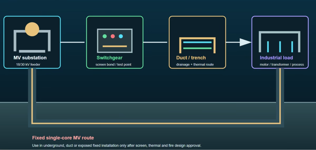
- Fixed-route applications
- Handling and termination
- Selection comparison
- Failure-mode controls
- Feichun certification scope
- Source audit
1. Engineering position
At 18/30 kV, insulation coordination, screen termination, creepage, clearances, earthing and accessory class must be controlled as one system. A lower-voltage accessory or unverified screen kit is not an acceptable substitution.
Phase formation, induced voltage, circulating current, screen bonding, cleating and touch-voltage control are part of the route design. The source does not provide armour or a screen cross-section for this target record.
The 12 (xD) value is a laying factor. It does not qualify the cable for repeated flexing, reeling, festoon, drag-chain or torsional service.
All eleven matrix rows are reproduced exactly, including the supplied 615 A and 421 A air-flat values. Missing values are not filled from another product family.
2. Designation and construction logic
| Designation / layer | Engineering reading | Design consequence | Evidence |
|---|---|---|---|
| YXC7V (TSE) | National designation retained in the product title. | Use the complete voltage, construction and standard record in procurement; do not rely on the code alone. | Supplied title |
| N2XSY (IEC) | IEC-oriented designation for single-core XLPE copper/PVC construction. | Coordinate conductor screen, XLPE, insulation screen, metallic screen, sheath and 18/30 kV accessories. | Supplied title |
| Copper conductor | Phase conductor material is copper. | Use the exact DC resistance and thermal row for voltage-drop and ampacity calculations. | Supplied construction |
| XLPE + semiconducting screens | Extruded dielectric with controlled electric-field interfaces. | Screen continuity, stripping length, cleanliness and stress control are critical at joints and terminations. | Supplied construction |
| Concentric copper wires + copper tape | Metallic screen around the insulation screen. | Bonding, earth-fault duty, induced current and touch voltage need project calculations; no screen area is invented here. | Supplied construction |
| PVC outer sheath | External environmental and mechanical interface. | Do not relabel the product as LSZH or halogen-free without a matching declaration. | Supplied construction |
3. Standards and evidence
| Reference | Role in the supplied record | Engineering interpretation | Release boundary |
|---|---|---|---|
| IEC 60502-2 | Product standard. | Use as the product-standard basis for extruded-insulation MV cable design in the applicable voltage range and fixed-installation context. | Confirm project edition and Feichun conformity route. |
| TS IEC 60502 | National standard. | Retain the national reference in the schedule where required by the project or market. | Confirm national edition and contract basis. |
| IEC 60332-1-2 | Flame-retardant reference. | It is a single-cable vertical flame-propagation test method; it is not a complete grouped-cable fire declaration or CPR class. | Match the exact product test evidence. |
| PVC sheath | Specified outer sheath material. | Assess smoke, corrosive gas, fire stopping, UV, water, chemical and mechanical requirements for the actual route. | No LSZH claim supplied. |
4. Complete source specification
| Specification field | Reference value | Engineering interpretation | Evidence status |
|---|---|---|---|
| Product designation | YXC7V (TSE) – N2XSY (IEC) 18/30 kV | National TSE and IEC-oriented designations are retained separately in the procurement description. | Supplied source |
| International product description | N2XSY 18/30 kV XLPE insulated single core cables with copper conductor | Single-core fixed-installation MV cable architecture for energy-network routes. | Supplied source |
| Product standard | IEC 60502-2 | Use the project-adopted edition and the exact Feichun conformity file for release. | Supplied source |
| National standard | National TS IEC 60502 | Retain the national reference exactly as supplied; confirm the contract edition where applicable. | Supplied source |
| Application | These are cables with low dielectric losses used in energy network with sudden load changes. Laid in residental or industrial areas, underground or in ducts. | This wording defines fixed energy-network service; it does not establish reeling, festoon or continuous-flex qualification. | Supplied source |
| Number of cores | 1 | Single-core formation requires deliberate screen bonding, phase spacing, cleating and induced-current control. | Supplied source |
| Conductor | Copper | Copper conductor resistance, voltage drop and thermal capacity remain cross-section and installation dependent. | Supplied source |
| Conductor flexibility | Not stated in the supplied target record | Do not upgrade the product to Class 2, flexible, reeling or drag-chain status without the controlled Feichun construction record. | Not supplied |
| Conductor screen | Semi-conducting compound (XLPE) | Creates the controlled electric-field transition from conductor to XLPE insulation. | Supplied source |
| Insulation | XLPE | Primary extruded solid dielectric for the 18/30 kV system class. | Supplied source |
| Insulation screen | Semi-conducting compound (XLPE) | Controls the outer XLPE electric-field boundary before the metallic screen. | Supplied source |
| Semi-conducting tape | Crape tape | Source wording is preserved exactly; stripping and preparation must follow the approved accessory system. | Supplied source |
| Metallic screen | Concentric / Copper wires + copper tape | The metallic screen is an electrical screen and earth-fault path; its section and bonding method are not provided in this target record. | Supplied source |
| Outer sheath | PVC | PVC is the specified environmental and mechanical outer interface. No LSZH claim is added. | Supplied source |
| Rated Voltage Uo/U (Um) | 18/30 kV | Confirm system earthing, switching, withstand, accessories and termination class against the project. | Supplied source |
| Operating temperature, range | -20 … 90 °C | Apply with actual ambient, soil, duct, spacing, grouping, screen losses and accessory limits. | Supplied source |
| Short-circuit max. conductor temperature | 250 °C | Use with conductor I²t, protection clearing time and complete joint and termination system. | Supplied source |
| Bending factor when laying | 12 (xD) | A laying-radius factor only; it is not a continuous-flex or dynamic-bending qualification. | Supplied source |
| Max. conductor temperature in service | 90 °C | The thermal design must be corrected for formation, ambient, soil, duct and grouping conditions. | Supplied source |
| Flame retardant | IEC 60332-1-2 | A single-cable flame-propagation test reference; no CPR class is inferred. | Supplied source |
| Source record | Generated 8/4/26 — www.nexans.com.tr — Page 1 / 2 and Page 2 / 2 | The page labels and source metadata are reproduced exactly as provided. | Supplied source |
| Source disclaimer | All drawings, designs, specifications, plans and particulars of weights, size and dimensions contained in the technical or commercial documentation of Nexans is indicative only and shall not be binding on Nexans or be treated as constituting a representation on the part of Nexans. | Use the controlled Feichun release and project-approved documents for procurement and installation decisions. | Supplied source |
5. Complete technical matrix — 18/30 kV
The following matrix preserves every supplied value. Air ratings are stated for 30 °C in flat and trefoil formations; the buried rating is stated for 20 °C in trefoil formation. The source does not supply a buried-flat rating, so none is inferred.
| Cross section [mm²] | Nom. outer diam. [mm] | Approx. weight [kg/km] | Max. DC Resist. Cond. 20 °C [Ohm/km] | Perm. current rating in air 30 °C — flat [A] | Current rating in air 30 °C — trefoil [A] | Perm. current rating buried 20 °C — trefoil [A] | Short circuit conductor 1 s [kA] |
|---|---|---|---|---|---|---|---|
| 50 | 31.0 | 1300 | 0.387 | 286 | 238 | 196 | 7.2 |
| 70 | 33.0 | 1600 | 0.268 | 356 | 296 | 239 | 10 |
| 95 | 35.0 | 1900 | 0.193 | 434 | 361 | 285 | 13.6 |
| 120 | 36.0 | 2250 | 0.153 | 500 | 417 | 323 | 17.2 |
| 150 | 38.0 | 2500 | 0.124 | 559 | 473 | 361 | 21.4 |
| 185 | 39.0 | 3000 | 0.099 | 637 | 543 | 406 | 26.5 |
| 240 | 42.0 | 3500 | 0.0754 | 745 | 641 | 469 | 34.3 |
| 300 | 44.0 | 4250 | 0.06 | 846 | 735 | 526 | 42.9 |
| 400 | 47.0 | 5250 | 0.047 | 938 | 845 | 590 | 57.2 |
| 500 | 51.0 | 6250 | 0.037 | 615 | 1000 | 688 | 71.5 |
| 630 | 55.0 | 7750 | 0.028 | 421 | 1150 | 774 | 90.1 |
The 500 mm² and 630 mm² air-flat values of 615 A and 421 A are reproduced exactly as supplied. They are unusual relative to adjacent rows and should be confirmed against the controlled product sheet before thermal design or tender release.
6. Derived installation checks
| Cross section | Published outer diameter | Source laying factor | Derived minimum laying radius | Mass conversion |
|---|---|---|---|---|
| 50 mm² | 31.0 mm | 12 × D | 372.0 mm | 130.0 kg/100 m |
| 70 mm² | 33.0 mm | 12 × D | 396.0 mm | 160.0 kg/100 m |
| 95 mm² | 35.0 mm | 12 × D | 420.0 mm | 190.0 kg/100 m |
| 120 mm² | 36.0 mm | 12 × D | 432.0 mm | 225.0 kg/100 m |
| 150 mm² | 38.0 mm | 12 × D | 456.0 mm | 250.0 kg/100 m |
| 185 mm² | 39.0 mm | 12 × D | 468.0 mm | 300.0 kg/100 m |
| 240 mm² | 42.0 mm | 12 × D | 504.0 mm | 350.0 kg/100 m |
| 300 mm² | 44.0 mm | 12 × D | 528.0 mm | 425.0 kg/100 m |
| 400 mm² | 47.0 mm | 12 × D | 564.0 mm | 525.0 kg/100 m |
| 500 mm² | 51.0 mm | 12 × D | 612.0 mm | 625.0 kg/100 m |
| 630 mm² | 55.0 mm | 12 × D | 660.0 mm | 775.0 kg/100 m |
Derived values are arithmetic screening checks: minimum laying radius = 12 × nominal outer diameter; mass per 100 m = approximate kg/km ÷ 10. They do not replace the controlled installation method, pulling calculation or accessory manufacturer’s radius.
7. Electrical, thermal and short-circuit design
Use the supplied 20 °C DC resistance as a source value only. AC resistance, reactance, power factor, route length, formation and screen-bonding losses must be established for the installation.
Air ratings are stated for 30 °C; buried trefoil ratings are stated for 20 °C. Apply corrections for ambient, soil thermal resistivity, ducts, spacing, grouping, sheath losses and accessory limits.
The source gives a 250 °C maximum conductor short-circuit temperature and one-second conductor values. Verify protection I²t with the actual conductor, screen, joint and termination system.
No metallic-screen cross-section or screen one-second current value is supplied for this target record. Do not infer a fault-current capability from the presence of copper wires and tape.
8. Layer-by-layer cross-section
The SVG is a conceptual engineering reconstruction of the supplied layer sequence. It is not a manufacturing drawing and does not add unprovided dimensions, armour, LSZH compounds or screen sections.
9. Single-core electrical and screen system
Semiconducting screens must remain clean, concentric and continuous through joints and terminations to avoid local field concentration.
Choose bonding from system voltage, route length, induced voltage, circulating-current limits, earth-fault duty and local earthing rules.
The supplied construction lists no steel armour. Use rollers, cleats, ducts, supports and entry protection that prevent PVC and screen damage.
Screen stripping, insulation diameter, sheath diameter, stress-control components and phase termination must match the ordered 18/30 kV cable size.
10. Fire and PVC performance boundary
The listed reference concerns single-cable vertical flame propagation. It must not be presented as a grouped-cable fire class or as proof of low smoke and halogen-free performance.
Confirm smoke, corrosive gas, fire stopping, penetrations, ventilation, UV, chemical exposure and local construction requirements for the route.
The target source does not state any CPR fire subclass or low-smoke/halogen-free classification. None is added to this article.
Certification is configuration-specific. The exact Feichun product dossier must control the declared test result, market mark and ordered construction.
11. Fixed-route applications
Use after voltage, insulation-coordination, screen-bonding, thermal, voltage-drop and protection studies are complete.
Check soil thermal resistivity, water exposure, drainage, route spacing, joint access, mechanical protection and fault return paths.
Check duct fill, pulling tension, sidewall pressure, entry radius, phase formation, heat dissipation and water management.
Evaluate substations, plant feeders and shore-side MV infrastructure for corrosion, flooding, impact, fire, maintenance and earthing.
The supplied record establishes fixed-route service and a laying factor, not continuous flexing. Select a dedicated dynamic cable for reeling, festoon or drag-chain motion.
12. Handling and termination
- Confirm the exact controlled conductor size, matrix row, revision, outer diameter, mass and accessory family before delivery.
- Apply the 12×D laying factor to the ordered diameter. The arithmetic screening radii span 372.0 mm for 50 mm² to 660.0 mm for 630 mm².
- Keep the drum aligned with the pay-off direction. Prevent reverse winding, uncontrolled twist, flange impact and local PVC sheath damage.
- Use rollers and supports that control radius and sidewall pressure. Do not pull against a sharp duct entry or force the copper screen around a local obstruction.
- Prepare the conductor screen, XLPE insulation, semiconducting screen, copper wires, copper tape and PVC sheath using the approved 18/30 kV joint or termination method.
- Record screen continuity, bonding arrangement, phase identification, conductor resistance, insulation and sheath tests, torque and accessory inspection before energisation.
- Complete MV withstand or partial-discharge tests where specified by the project and retain the product record, batch, test results and as-built route documentation.
13. Selection comparison for engineers
| Requirement | YXC7V / N2XSY reference | What must be verified | Engineering decision |
|---|---|---|---|
| 18/30 kV fixed single-core feeder | Cu / XLPE / semiconducting screens / concentric copper wires + copper tape / PVC. | System earthing, screen bonding, conductor size, formation, accessories and protection. | Candidate after exact-size release. |
| 50–240 mm² selection | Published diameter 31.0–42.0 mm; DCR 0.387–0.0754 Ohm/km; buried trefoil 196–469 A. | Voltage drop, route correction, pulling, screen duty and termination dimensions. | Use the exact matrix row. |
| 300–630 mm² selection | Published diameter 44.0–55.0 mm; DCR 0.06–0.028 Ohm/km; buried trefoil 526–774 A. | Thermal correction, duct capacity, joint size, drum handling and installation radius. | Use the exact matrix row. |
| 500 / 630 mm² air-flat values | 615 A and 421 A as supplied. | Confirm these unusual adjacent-row values against the controlled source before ampacity release. | Do not silently correct source data. |
| Reeling / festoon / drag chain | 12×D laying factor and fixed-route application wording only. | Cycles, torsion, speed, acceleration, tensile load, dynamic bend radius and environmental tests. | Select a dedicated dynamic cable family. |
14. Failure-mode controls
| Failure mode | Mechanism | Control action | Release evidence |
|---|---|---|---|
| Wrong voltage class | 18/30 kV cable is confused with a lower-voltage accessory system. | Lock voltage, insulation level, screen termination and accessory class on the purchase schedule. | Approved cable and accessory schedule. |
| Matrix-row mixing | Diameter, mass, resistance, ampacity and fault values are copied across sizes. | Use the exact cross-section row on every calculation, drum record, joint schedule and test sheet. | Controlled matrix and released drawing. |
| Radius violation | 12×D is applied to the wrong diameter or ignored at duct entries. | Calculate the ordered-size radius and control rollers, entry geometry and support spacing. | Method statement and inspection. |
| Screen fault-path error | Presence of copper wires and tape is treated as a complete earth-fault guarantee. | Verify screen section, bonding, parallel paths, clearing time, temperature and joint capability from controlled data. | Earthing and short-circuit study. |
| Air-flat anomaly ignored | 615 A and 421 A are used without checking the source revision. | Confirm the supplied values against the controlled release before thermal design. | Signed datasheet verification. |
| Dynamic misuse | Fixed-route PVC cable is installed on a reel, festoon or energy chain. | Select a qualified dynamic cable with mechanical cycle and torsion evidence. | Dedicated dynamic-cable data required. |
15. Feichun Cable certification and project assurance
Certification and market documentation apply to the exact conductor size, screen geometry, sheath compound, accessory system, destination market and shipment batch.
Confirm conductor resistance, outer diameter, mass, thermal ratings, short-circuit duty, sheath tests, fire declaration and accessory compatibility for the ordered 18/30 kV construction.
Feichun can develop the copper / XLPE / concentric copper-screen / PVC architecture around the actual route, protection system, earthing design and project documentation.
ATEX, IECEx, VDE, CE, UKCA, EAC and Russian Fire Safety documentation must be matched to the applicable product scope; certification capability is not an automatic claim for every size or construction.
16. Source and revision audit
| Source | Use in this article | Status and limitation |
|---|---|---|
| Nexans Türkiye YXC7V / N2XSY family page | Family designation and related product-family context. | External family reference; the supplied Feichun target record remains primary for every listed matrix value. |
| IEC 60502-2 official publication | Product-standard and fixed-installation engineering context. | Confirm the adopted edition and exact Feichun conformity route. |
| IEC 60332-1-2 official publication | Single-cable flame-propagation test context. | Test-method reference only; it is not a complete grouped-cable fire declaration. |
| User-supplied source record | All voltage, temperature, bending, flame, construction, page metadata and eleven matrix rows are reproduced. | Primary record for this article. Missing screen section, screen fault rating and buried-flat rating are not inferred. |
| Derived calculations | 12×D radius screening and kg/100 m conversion. | Arithmetic only; not a substitute for the controlled installation method or accessory instruction. |

![This article treats DE HIGHLY FLEXIBLE 4X35 MM2 REELING CABLE NSHTOEU 0.6/1KV as the purchaser's supplied description and translates it into a controlled cable specification. The published NSHTOEU reference construction is a four-core, 35 mm²-per-core, 0.6/1 kV flexible reeling cable with fine-stranded tinned copper, rubber/EPR insulation, a rubber inner sheath, polyester reinforcement and a heavy-duty rubber outer sheath [1]. Feichun can develop a functional equivalent, but the released drawing, test plan and project conditions must govern the final product.](https://feichuncables.com/blog/wp-content/uploads/image-1777-400x225.avif "DE HIGHLY FLEXIBLE 4X35 MM2 REELING CABLE NSHTOEU 0.6/1KV — an engineering guide for dynamic power service 3")
![The supplied string combines a VAHLE procurement or marking reference with the TFCrane family name and the medium-voltage configuration 3×35 + 3×25/3. The current public TFCrane catalogue identifies the corresponding R-(N)TSCGEWÖU family as a flexible medium-voltage reeling cable based on DIN VDE 0250-813, with four selectable voltage classes from 3.6/6 kV to 12/20 kV [2]. Because the user string does not state the voltage class, this guide preserves every published variant and makes the voltage selection a deliberate RFQ gate.](https://feichuncables.com/blog/wp-content/uploads/image-1778-400x225.avif "LT-GUM-R-TFCRANE (N) TSCGEWOEU 3X35 & 3X25/3 REELING CABLE TFCRANE R MARK VAHLE — VAHLE marking, TFCrane reference and Feichun equivalent engineering guide 4")