When a 20 kg Rock Block Falls 4 Meters onto Your Trailing Cable at the Portal Mouth — The Complete Engineering Guide to Heavy-Duty Jacketing for Portal Access Zones. AS/NZS 1802 Type 209 Designation Decoded. The 3C+E Configuration for Core-Balance-Protected 3.3kV Systems. The Symmetrical 3.3/3.3kV Earth-Fault-Limited Voltage System. Portal Zone Rock Fall Mechanics in Archean Greenstone Belt Geology. Impact Energy Calculations: Mass × Height × Gravity. Double-Sheath Construction vs Steel Wire Braid Reinforcement. Sandvik MT720/MB670 OEM Cable Specifications at 3.3kV. Cable Reeler Drum Compatibility at Larger OD. Cross-Standard Equivalence: IEC 60502-1 and DIN VDE 0250-812 NSSHÖU. Feichun MINETRAIL-FX Heavy-Duty Portal Cable with Reinforced CPE Jacketing. Bulyanhulu and Geita Mine-Specific Considerations. Tanzania Mining Commission (TMAA) Regulatory Requirements. 28+ References.
当一块 20 kg 的岩块从 4 米高处砸向平硐口的拖曳电缆——平硐入口区重型护套完整工程指南。AS/NZS 1802 Type 209 型号解析、3C+E 芯线配置(用于零序保护的 3.3kV 系统)、对称 3.3/3.3kV 限制接地故障电压系统、太古宙绿岩带地质条件下的平硐落石力学、冲击能量计算、双层护套 vs 钢丝编织增强结构、山特维克 MT720/MB670 OEM 电缆规格(3.3kV)、大外径卷线器兼容性、跨标准等效(IEC 60502-1 / DIN VDE 0250-812)、飞纯 MINETRAIL-FX 重型平硐电缆(增强 CPE 护套)、布尔延胡卢和盖塔矿山专项考量、坦桑尼亚矿业委员会(TMAA)法规要求。28+ 参考文献。
Tanzania Portal Access: Heavy-Duty Jacketing on Type 209 3.3/3.3kV 3×50mm² for African Rock Falls
Complete Portal Trailing Cable Engineering Guide
When a 20 kg Rock Block Falls 4 Meters onto Your Trailing Cable at the Portal Mouth — The Complete Engineering Guide to Heavy-Duty Jacketing for Portal Access Zones. AS/NZS 1802 Type 209 Designation Decoded. The 3C+E Configuration for Core-Balance-Protected 3.3kV Systems. The Symmetrical 3.3/3.3kV Earth-Fault-Limited Voltage System. Portal Zone Rock Fall Mechanics in Archean Greenstone Belt Geology. Impact Energy Calculations: Mass × Height × Gravity. Double-Sheath Construction vs Steel Wire Braid Reinforcement. Sandvik MT720/MB670 OEM Cable Specifications at 3.3kV. Cable Reeler Drum Compatibility at Larger OD. Cross-Standard Equivalence: IEC 60502-1 and DIN VDE 0250-812 NSSHÖU. Feichun MINETRAIL-FX Heavy-Duty Portal Cable with Reinforced CPE Jacketing. Bulyanhulu and Geita Mine-Specific Considerations. Tanzania Mining Commission (TMAA) Regulatory Requirements. 28+ References.
当一块 20 kg 的岩块从 4 米高处砸向平硐口的拖曳电缆——平硐入口区重型护套完整工程指南。AS/NZS 1802 Type 209 型号解析、3C+E 芯线配置(用于零序保护的 3.3kV 系统)、对称 3.3/3.3kV 限制接地故障电压系统、太古宙绿岩带地质条件下的平硐落石力学、冲击能量计算、双层护套 vs 钢丝编织增强结构、山特维克 MT720/MB670 OEM 电缆规格(3.3kV)、大外径卷线器兼容性、跨标准等效(IEC 60502-1 / DIN VDE 0250-812)、飞纯 MINETRAIL-FX 重型平硐电缆(增强 CPE 护套)、布尔延胡卢和盖塔矿山专项考量、坦桑尼亚矿业委员会(TMAA)法规要求。28+ 参考文献。
1. The Problem: Portal Access Zones Are Where Trailing Cables Go to Die
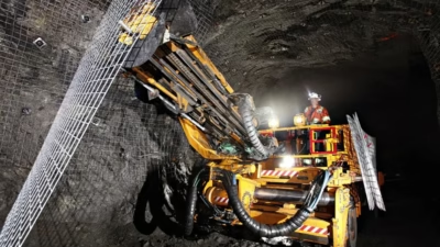
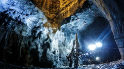
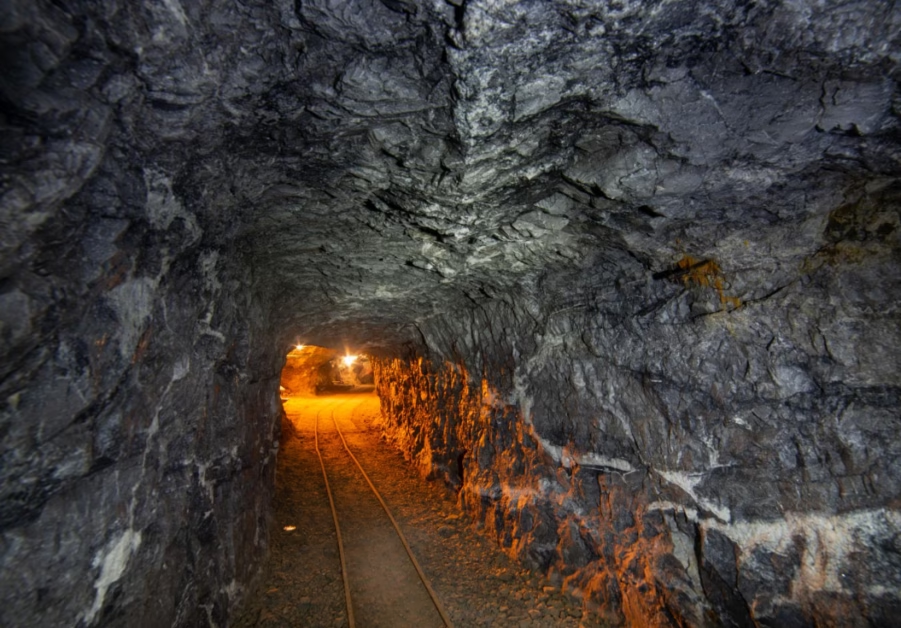
Tanzania’s underground gold mines — Bulyanhulu (Barrick / Twiga Minerals), North Mara (Barrick), Geita Underground (AngloGold Ashanti), New Luika (Shanta Gold) — operate fleets of Sandvik continuous miners, roadheaders, and load-haul-dump machines powered through trailing cables at 3.3/3.3kV. The portal access zone — the first 50–200 meters from the adit entrance into the underground workings — is the single most hostile environment for a trailing cable in any mine. The portal zone intersects deeply weathered, fractured rock that produces continuous rock falls: angular blocks of 0.5–50 kg dropping from heights of 2–5 meters onto the cable trail. A single impact from a 20 kg block falling 4 meters delivers ~785 joules of kinetic energy — enough to crush through a standard 3.0 mm trailing cable sheath and puncture the insulation in one event. The result is an immediate earth fault, machine shutdown, and emergency cable replacement in the most logistically difficult section of the mine. This guide provides the engineering framework for specifying a heavy-duty jacketed Type 209 3.3/3.3kV 3×50mm² trailing cable that survives portal zone rock falls, meets Sandvik OEM requirements, and complies with Tanzania Mining Commission safety regulations.
The portal access zone is an engineering paradox. It is both the most accessible section of the mine (closest to surface, closest to the workshop, closest to the cable stores) and the most destructive to trailing cables. The paradox exists because the rock mass at the portal zone is invariably the worst in the entire mine. Every underground mine transitions from surface through a weathered zone, then a fractured transition zone, then competent rock. The portal punches through the worst ground first. In Tanzania’s Lake Victoria Goldfield, where Archean greenstone belt rocks have been exposed to tens of millions of years of tropical weathering, the portal zone rock mass is typically classified as Q = 0.01–0.1 on the NGI Q-system — “exceptionally poor” to “extremely poor” ground — requiring heavy ground support (steel sets, shotcrete, rock bolts, mesh) that itself creates additional cable snag and abrasion hazards.
The economic calculus is straightforward. A Sandvik MT720 roadheader operating at Bulyanhulu’s deepening declines produces approximately 15–25 meters of advance per day in development headings. If the machine is idle because its 3.3kV trailing cable has been destroyed by a portal zone rock fall, the development delay costs approximately USD 30,000–80,000 per day in deferred production (the development heading feeds future stoping panels). Over a 4-week cable replacement cycle — sourcing, shipping, termination, commissioning — the cumulative cost is USD 0.8–2.2 million. A heavy-duty jacketed cable that costs 25–40% more than a standard trailing cable but survives two to three times longer in the portal zone pays for itself within the first prevented failure event.
坦桑尼亚地下金矿(布尔延胡卢、北马拉、盖塔地下、新卢伊卡)使用 3.3/3.3kV 拖曳电缆为山特维克连采机和掘进机供电。平硐入口区(距硐口 50–200 米)是整个矿山中对拖曳电缆最具破坏性的环境——深度风化的太古宙绿岩带岩体持续产生 0.5–50 kg 的落石,从 2–5 米高处砸向电缆线路。一块 20 kg 岩块从 4 米高处坠落产生约 785 焦耳的冲击能量——足以一次性压穿标准 3.0 mm 护套并刺穿绝缘层。山特维克 MT720 掘进机的日停产损失约 USD 30,000–80,000,4 周电缆更换周期的累计损失达 USD 80–220 万。重型护套电缆成本仅增加 25–40%,但在平硐区的使用寿命延长 2–3 倍——首次避免的故障事件即可收回全部投资。
2. What Is AS/NZS 1802 Type 209 and How Does It Differ from Type 241?
AS/NZS 1802 Type 209 belongs to the same three-digit type code system as Type 241, but encodes a different core configuration optimized for higher-voltage (3.3kV) trailing cable systems where earth-fault detection philosophy diverges from the pilot-wire approach used at 1.1kV.
| Digit Position | What It Encodes | Type 241 | Type 209 |
|---|---|---|---|
| First digit | Sheath type (outer protection) | 2 = CSP/CPE enhanced abrasion | 2 = CSP/CPE enhanced abrasion (identical) |
| Second digit | Core configuration | 4 = Earth (E) + Pilot (P) cores | 0 = Earth (E) core only — no pilot cores |
| Third digit | Number of power cores / voltage class | 1 = Three-core, 1.1kV class | 9 = Three-core, 3.3kV class |
The critical difference is the second digit. Type 241 (digit “4”) includes both earth and earth monitoring pilot cores — the 3C+E+P configuration essential for pilot-wire earth continuity monitoring (ECM). Type 209 (digit “0”) includes an earth core but no pilot cores — the 3C+E configuration used on systems where earth-fault detection is performed by a core-balance current transformer (CBCT) at the supply end of the cable, rather than by a pilot wire running through the cable itself.
At 1.1kV, pilot-wire ECM is the standard protection philosophy because the low system voltage makes sensitive zero-sequence current detection difficult — the fault current is very small (2–5A) and the CBCT must distinguish it from normal load current unbalance. At 3.3kV, the higher system voltage allows the use of more sensitive and reliable core-balance (zero-sequence) current transformers mounted at the cable entry gland that detect earth-fault currents down to 0.1–0.5A without requiring a pilot wire. Eliminating the three pilot cores (3×2.5mm²) reduces the cable’s overall diameter by approximately 3–5mm, which partially offsets the increased conductor size (50mm² vs 35mm²) and thicker insulation (2.0mm vs 1.2mm) required at 3.3kV. The result is a cable that provides equivalent earth-fault protection through a different, external detection method while maintaining a manageable overall diameter for cable reeler drum compatibility.
The third digit “9” designates the 3.3kV-class three-core configuration. At this voltage tier, the insulation thickness increases significantly (from ~1.2mm at 1.1kV to ~2.0mm at 3.3kV), the conductor cross-section increases to support higher-power machines (50mm² standard, versus 35mm² at 1.1kV), and the earth conductor cross-section increases proportionally (25mm² versus 16mm²). The full cable designation is therefore:
Type 209 3.3/3.3kV 3×50+1×25mm²Three 50mm² power cores + One 25mm² earth core
No pilot cores — earth fault detection by external CBCT
Enhanced abrasion CSP/CPE outer sheath
Type 209 与 Type 241 的关键区别在于第二位数字:”0″ 表示仅有接地芯、无导频芯(3C+E 配置),而 “4” 表示接地芯加导频芯(3C+E+P)。在 3.3kV 系统中,接地故障检测由电缆入口端的零序电流互感器(CBCT)完成,无需导频线——CBCT 可检测低至 0.1–0.5A 的故障电流。取消三根 2.5mm² 导频芯使电缆外径减少约 3–5mm,部分抵消了 3.3kV 所需的更厚绝缘(2.0mm vs 1.2mm)和更大导体截面(50mm² vs 35mm²)的尺寸增加。
3. The 3.3/3.3kV Symmetrical Voltage System — Scaling the EFL Principle
The 3.3/3.3kV designation applies the same earth-fault-limited (EFL) philosophy as the 1.1/1.1kV system described in our companion guide on Ghana Type 241 cables, but at three times the voltage. The symmetrical designation U₀/U = 3.3/3.3kV means that the cable insulation is designed for a maximum voltage of 3.3kV between any conductor and earth — both during normal operation and during a single-phase earth fault — because the neutral earthing resistor (NER) limits the fault current and prevents voltage rise on healthy phases.
| Parameter | Conventional 3.3kV (IEC) | EFL 3.3/3.3kV (AS/NZS) |
|---|---|---|
| Phase-to-phase voltage (U) | 3,300 V | 3,300 V |
| Phase-to-earth voltage (U₀) — normal | 1,905 V (3300/√3) | 1,905 V (3300/√3) |
| Phase-to-earth voltage — during earth fault | Up to 3,300 V (on healthy phases) | Limited to ~3,300 V (by NER design) |
| Cable insulation design voltage | U₀ = 1.9kV, U = 3.3kV → 1.9/3.3kV | U₀ = U = 3.3kV → 3.3/3.3kV |
| Earth-fault current | 200–10,000 A (depends on source) | 0.5–2 A (NER limited) |
| Touch voltage during earth fault | Potentially lethal | Safe — NER limits touch voltage to safe levels |
| Cable routine voltage test | 8.0 kV AC (per IEC 60502-1) | 8.0 kV AC (per AS/NZS 1802 Table 5.1) |
| Insulation thickness (50mm² EPR) | ~2.0mm (per IEC 60502-1) | ~2.0mm (per AS/NZS 1802) |
Why 3.3kV instead of 1.1kV? The decision to operate at 3.3kV is driven by two factors: voltage drop and machine power demand. At 1.1kV, a 50mm² trailing cable carrying 150A over 500 meters experiences a voltage drop of approximately 8.3% — exceeding the typical 5% maximum for motor starting. At 3.3kV, the same power is delivered at one-third the current (50A), reducing the voltage drop to approximately 2.8%. For the long trailing cable runs required in Tanzania’s deep decline developments — 500–1,000 meters from the nearest substation to the machine face — 3.3kV is the only practical voltage tier. Additionally, the larger machines used in Tanzanian hard-rock mining (Sandvik MT720 roadheaders drawing 250–350 kW, MB670 continuous miners with cutter motors exceeding 200 kW) require current levels that would demand impractically large conductors at 1.1kV.
Voltage drop comparison for 200 kW machine, 500m cable run, 50mm² Cu:At 1.1kV: I = 200,000 / (√3 × 1,100 × 0.85) ≈ 123 A
ΔV = √3 × 123 × (0.387 × 500/1000) = 41.2 V → 3.75% of 1,100V ✓
At 3.3kV: I = 200,000 / (√3 × 3,300 × 0.85) ≈ 41 A
ΔV = √3 × 41 × (0.387 × 500/1000) = 13.7 V → 0.42% of 3,300V ✓✓
At 1,000m cable run, 1.1kV drop doubles to 7.5% → unacceptable
At 1,000m cable run, 3.3kV drop doubles to 0.84% → still excellent
4. Type 209 3.3/3.3kV 3×50mm² — Construction Decoded
| Layer | Component | Material / Standard | Dimensions | Function |
|---|---|---|---|---|
| 1 | Power conductors (×3) | Tinned copper, Class 5 flexible per AS/NZS 1125 | 50 mm² each (Ø ~9.1 mm; 396 wires × 0.40 mm) | Three-phase power delivery to roadheader/continuous miner (~200–350 kW) |
| 2 | Earth conductor (×1) | Tinned copper, Class 5 flexible | 25 mm² (Ø ~6.8 mm; 196 wires × 0.40 mm) | Earth fault return path — machine frame to transformer neutral |
| 3 | Conductor screen | Semi-conducting EPR tape wrap | 0.5 mm radial per core | Electric field stress grading at conductor surface — essential at 3.3kV |
| 4 | Core insulation | EPR (Ethylene Propylene Rubber) per AS/NZS 3808 | 2.0 mm radial (power cores); 1.5 mm (earth core) | Dielectric withstand — 3.3kV; flexibility for trailing service |
| 5 | Insulation screen | Semi-conducting EPR tape + tinned copper braid (16mm² effective) | 0.5 mm radial per core | Electric field containment; individual core earth screen |
| 6 | Core identification | Color-coded: Red, White, Blue (power); Green/Yellow (E) | — | Phase and function identification per AS/NZS 1802 Clause 4.5 |
| 7 | Assembly / fillers | Extruded elastomeric fillers | — | Round cable profile; prevents core migration during flexing |
| 8 | Inner sheath (bedding) | CSP or CPE compound | ~1.2 mm radial | Core protection; additional crush resistance layer |
| 9 | Outer sheath | CSP (Hypalon) or CPE — enhanced abrasion grade (Type “2” prefix) | ~3.0–3.5 mm radial | Primary mechanical protection: abrasion, crush, cut, gouge, flame retardant, oil resistant |
Unlike the 1.1kV Type 241, the 3.3kV Type 209 requires semi-conducting screens on both the conductor surface (inner screen) and the insulation surface (outer screen) of each power core. At 3.3kV, the electric field stress at the conductor surface and at any air gaps between the conductor and insulation is high enough to cause partial discharge (corona) — microscopic electrical discharges in air voids that progressively erode the insulation and lead to premature failure. The semi-conducting screens eliminate air gaps and provide uniform electric field distribution across the insulation thickness. This is standard practice for medium-voltage cables per IEC 60502-2, but it is a critical construction detail that any trailing cable equivalent must replicate. A cable manufactured without proper screens at 3.3kV will fail from partial discharge erosion within 6–24 months — long before mechanical wear destroys it.
Overall cable diameter: Approximately 48–54 mm (significantly larger than the ~40mm of a 1.1kV Type 241). Cable mass: Approximately 4.2–4.8 kg/m. Minimum bending radius: 6×D (approximately 290–325 mm) for standard construction; 8×D (~385–430 mm) for heavy-duty jacketed variants. Maximum trailing length: Typically 400–1,000 meters per machine, exploiting the lower voltage drop at 3.3kV.
3.3kV Type 209 的关键构造差异在于半导电屏蔽层。在 3.3kV 电场应力下,导体表面和绝缘表面必须设置半导电 EPR 带包绕屏蔽层,以消除空气间隙、防止局部放电(电晕)——局部放电会在 6–24 个月内侵蚀绝缘层导致过早失效。整体电缆外径约 48–54 mm,质量约 4.2–4.8 kg/m——显著大于 1.1kV Type 241 的 ~40mm 和 ~3.0 kg/m。
5. Portal Zone Rock Fall Mechanics — Impact Energy on Cables
Understanding the destructive potential of rock falls on trailing cables requires quantifying the impact energy delivered to the cable surface. The governing equation is elementary mechanics, but the numbers it produces are sobering.
Impact energy: E = m × g × hWhere: m = falling rock mass (kg)
g = gravitational acceleration (9.81 m/s²)
h = fall height (m)
Impact velocity: v = √(2 × g × h)
| Rock Mass (kg) | h = 1 m | h = 2 m | h = 3 m | h = 5 m |
|---|---|---|---|---|
| 0.5 (gravel/spall) | 4.9 J | 9.8 J | 14.7 J | 24.5 J |
| 2.0 (small block) | 19.6 J | 39.2 J | 58.9 J | 98.1 J |
| 5.0 (medium block) | 49.1 J | 98.1 J | 147 J | 245 J |
| 10 (large block) | 98.1 J | 196 J | 294 J | 491 J |
| 20 (very large block) | 196 J | 392 J | 589 J | 981 J |
| 50 (massive slab) | 491 J | 981 J | 1,472 J | 2,453 J |
The color coding reveals the problem. Green cells (< 50 J) represent impacts that a standard trailing cable sheath can absorb without insulation damage. Amber cells (50–250 J) represent impacts that cause sheath deformation and potential insulation compression but may not cause immediate failure. Red cells (> 250 J) represent impacts that will penetrate the sheath and damage the insulation on a standard trailing cable — resulting in immediate or imminent electrical failure.
In the portal zone of a typical Tanzania underground mine, the most frequent rock fall events are in the 0.5–5 kg range (spalls and small blocks dislodged by blast vibration, stress relief, or water seepage) falling from 2–5 meters. These represent the amber-to-red transition zone — the exact energy range where standard sheathing fails but heavy-duty jacketing survives. The less frequent but catastrophic events (10–50 kg blocks from tunnel crown failure) are in the red zone regardless of cable construction — but even these events produce survivable cable damage on heavy-duty jacketed cables rather than complete cable destruction.
Contact Area and Stress Concentration
The impact energy alone does not determine cable damage — the contact area between the falling rock and the cable surface is equally critical. A rounded cobble distributes impact force over a contact area of approximately 20–50 mm² (Hertzian contact). An angular block with a sharp edge concentrates the same impact energy onto a contact area of 2–5 mm² — increasing the local pressure by a factor of 10–25×. This is why Archean greenstone belt rock falls are particularly destructive: the metabasalt and banded iron formation (BIF) lithologies that dominate Tanzania’s gold mines fracture into angular, sharp-edged blocks with high hardness (Mohs 6–7) that act as penetrating projectiles rather than blunt impactors.
Local contact pressure from angular rock impact:Rounded cobble: F/A = (m × g × h) / 30 mm² → 20 kg × 4m: 785 / 30 = 26 MPa
Angular block: F/A = (m × g × h) / 3 mm² → 20 kg × 4m: 785 / 3 = 262 MPa
Standard CPE sheath puncture threshold: ~80–120 MPa
Steel wire braid + CPE puncture threshold: ~350–500 MPa
Angular impact at 262 MPa → standard sheath fails ✗
Angular impact at 262 MPa → steel wire braid survives ✓
落石冲击能量计算:E = m × g × h。在坦桑尼亚矿山平硐区,最常见的落石事件为 0.5–5 kg 的岩块从 2–5 米高处坠落——对应 10–245 焦耳的冲击能量——正处于标准护套失效而重型护套存活的临界区间。关键因素是接触面积:太古宙绿岩带岩石断裂成尖锐棱角状,将冲击力集中在 2–5 mm² 的接触面上,使局部压力高达 262 MPa——远超标准 CPE 护套的 80–120 MPa 穿刺阈值,但低于钢丝编织+CPE 的 350–500 MPa 阈值。
6. Why Standard Trailing Cable Sheathing Fails at Portals
A standard AS/NZS 1802 Type 209 trailing cable — even with the enhanced abrasion CSP/CPE sheath designated by the “2” prefix — is designed to withstand the distributed, progressive mechanical stresses of normal trailing service: cyclic bending at the reeler drum, continuous floor abrasion, and occasional shuttle car run-over. These are all quasi-static or low-velocity loading events where the sheath material has time to deform elastically and distribute the force across a relatively large area.
Rock fall impact is a fundamentally different loading regime. It is a high-velocity, point-load, dynamic event where the sheath must absorb a concentrated energy pulse in milliseconds. The key differences between normal trailing stresses and rock fall impact are:
| Parameter | Normal Trailing Service | Portal Zone Rock Fall |
|---|---|---|
| Loading rate | Quasi-static (seconds to minutes) | Dynamic — milliseconds (impact velocity 3–10 m/s) |
| Contact area | Large: tire (5,000 mm²), floor (100+ mm²) | Small: angular rock edge (2–50 mm²) |
| Peak pressure | 5–30 MPa (shuttle car tire) | 50–500+ MPa (angular rock, concentrated) |
| Energy per event | Low — elastic deformation dominates | High — 10–2,500 J per impact; plastic deformation and penetration |
| Frequency | Continuous / cyclic | Stochastic — 1–50 events per day in active portal zones |
| Material response | Viscoelastic — sheath recovers between events | Exceeds elastic limit — permanent indentation, cut, or penetration |
| Failure mode | Progressive wear (abrasion, fatigue) | Sudden penetration — sheath cut → insulation exposed → earth fault |
The fundamental limitation of a single-layer elastomeric sheath under impact loading is that elastomers are excellent at absorbing distributed, slow-rate energy (which is why they are ideal for normal trailing service) but poor at resisting concentrated, high-rate penetration. When an angular rock edge strikes the cable at 6 m/s (equivalent to a 2-meter fall), the sheath material does not have time to redistribute the stress through viscoelastic flow. The contact point experiences a localized strain rate that exceeds the material’s dynamic fracture toughness, and the rock edge cuts through the sheath like a knife through rubber — because, in mechanical terms, that is exactly what is happening.
This is the engineering problem that heavy-duty jacketing solves. The jacketing interposes a high-stiffness, load-distributing layer between the impact point and the underlying elastomeric sheath, converting a concentrated point load into a distributed compressive load that the sheath can absorb within its elastic limit.
7. Heavy-Duty Jacketing Architectures for Portal Zones
Three distinct jacketing architectures are used in the global mining industry to protect trailing cables in high-impact zones. Each has different performance characteristics, flexibility implications, and cost impacts.
Architecture 1 — Double-Sheath (Dual-Layer Elastomer)
The simplest approach: apply a second elastomeric sheath layer over the standard outer sheath, increasing the total sheath thickness from ~3.0mm to ~5.5–6.5mm. The two layers are bonded during extrusion to prevent delamination. The double-sheath approach provides approximately 1.8–2.2× the impact resistance of a single sheath — sufficient for low-energy rock falls (< 100 J) but inadequate for the 100–500 J events common in Tanzania portal zones. The principal advantage is that the cable retains near-standard flexibility (minimum bending radius remains 6×D). The disadvantage is limited improvement for the exact threat it is meant to address.
Architecture 2 — Steel Wire Braid (SWB) Reinforcement
A layer of galvanized steel wires (typically 0.5–1.0mm diameter) braided at 45–60° pitch angle over the inner sheath, covered by the outer elastomeric sheath. The steel wire braid serves as a distributed armor that converts point-load impacts into distributed pressure over a much larger cable surface area. The braid coverage (percentage of cable surface covered by steel wires) is typically 85–95%. The SWB architecture provides 3–5× the impact resistance of a standard sheath — sufficient for rock falls up to 500 J. The braid also provides significant cut and gouge resistance, preventing angular rock edges from penetrating to the insulation. The trade-off is increased cable stiffness: minimum bending radius increases from 6×D to 8×D, which requires verification of cable reeler drum compatibility.
Architecture 3 — Steel Wire Armor (SWA) with Full Interlock
A helically wound layer of interlocking galvanized steel strips (typically 0.8–1.5mm × 8–12mm) applied over the inner sheath, covered by the outer sheath. This is the heaviest-duty protection, providing 5–10× the impact resistance of a standard sheath — sufficient for rock falls exceeding 1,000 J. However, the fully interlocking armor increases the cable’s minimum bending radius to 12–15×D, effectively making the cable unsuitable for reeler drum operation. SWA-armored cables are used only in fixed or semi-fixed installations — for example, the main trunk cable from the portal substation to the first underground junction box — not for the trailing cable on the mobile machine itself.
| Parameter | Standard Single Sheath | Double Sheath | Steel Wire Braid (SWB) | Steel Wire Armor (SWA) |
|---|---|---|---|---|
| Impact resistance (approx.) | 50–80 J | 100–170 J | 250–500 J | 500–2,000+ J |
| Min. bending radius | 6×D | 6×D | 8×D | 12–15×D |
| Cable OD increase | — | +5–7mm | +4–6mm | +8–12mm |
| Mass increase | — | +15–20% | +25–35% | +50–80% |
| Reeler drum compatible? | Yes | Yes (verify OD) | Yes — with 8×D drum verification | No — fixed installation only |
| Cost premium | — | +15–25% | +25–40% | +40–60% |
| Suited for portal trailing cable? | Inadequate | Marginal — small rock falls only | Optimal — best balance of protection and flexibility | Overengineered for trailing; use for fixed trunk cables |
For trailing cables that must pass through portal access zones on cable reeler drums, the steel wire braid (SWB) architecture provides the optimal balance of impact protection (250–500 J — covering the vast majority of portal rock fall events), retained flexibility (8×D minimum bend radius — compatible with Sandvik reeler drums when verified), and reasonable cost premium (25–40%). The Feichun MINETRAIL-FX uses this architecture.
三种重型护套结构:双层弹性体护套(抗冲击约 100–170 J,弯曲半径保持 6×D)、钢丝编织增强(250–500 J,弯曲半径 8×D)、钢丝铠装联锁(500–2,000+ J,弯曲半径 12–15×D、不适用于卷线器)。对于必须通过平硐区的拖曳电缆,钢丝编织(SWB)架构是最佳选择——覆盖绝大多数平硐落石事件,同时保持与山特维克卷线器的兼容性。飞纯 MINETRAIL-FX 采用此架构。
8. Sandvik MT720/MB670 OEM Cable Requirements at 3.3kV
Sandvik Mining and Rock Solutions specifies 3.3kV trailing cable requirements for its larger machine models in the Electrical Installation and Maintenance Manual. The Sandvik MT720 roadheader and the larger configurations of the MB670 continuous miner — both common in Tanzania’s hard-rock underground gold mines — define cable requirements that must be met by any replacement cable, including heavy-duty jacketed variants.
| Parameter | Sandvik OEM Requirement | AS/NZS 1802 Minimum | Feichun MINETRAIL-FX Specification |
|---|---|---|---|
| Cable type | AS/NZS 1802 Type 209 (or approved equivalent) | Type 209 | Type 209 equivalent — documented |
| Voltage | 3.3/3.3kV EFL system | 3.3/3.3kV | Tested to 8.0kV AC routine; insulation ≥ 2.0mm EPR with screens |
| Power conductors | 3 × 50 mm² Class 5 tinned Cu | Class 5 per AS/NZS 1125 | 3 × 50 mm² Class 5 tinned Cu per IEC 60228 |
| Earth conductor | 1 × 25 mm² Class 5 tinned Cu | ≥ 50% of power core area | 1 × 25 mm² Class 5 tinned Cu |
| Conductor screens | Semi-conducting EPR on each power core | Required above 1.9/3.3kV | Semi-conducting EPR tape, 0.5mm radial |
| Insulation screens | Semi-conducting EPR + Cu braid (16mm²) | Required above 1.9/3.3kV | Semi-conducting EPR + Cu braid per IEC 60502-2 |
| Standard outer diameter | 48–56 mm (must fit cable reeler guide rollers) | — | 52 ± 1.5 mm (standard) / 57 ± 2 mm (FX heavy-duty) |
| Heavy-duty OD allowance | Up to 62 mm with modified guide rollers | — | 57 mm FX fits within 62mm modified guide limit |
| Min. bending radius (standard) | 6×D (≤ 336 mm for 56mm OD) | 6×D | 6×D standard / 8×D for FX (≤ 456mm) |
| Crush resistance | ≥ 15 kN/100mm (3.3kV requirement higher than 1.1kV) | Per AS/NZS 1802 Table 5.2 | 18 kN/100mm (FX with SWB) |
| Flame retardancy | IEC 60332-1 (single cable vertical) | AS/NZS 1802 Clause 5.4 | IEC 60332-1 + IEC 60332-3 Cat. C |
| Sheath abrasion | ≤ 200 mm³ (DIN 53516 / ISO 4649) | Per AS/NZS 3808 | ≤ 140 mm³ — Feichun CPE compound |
The Sandvik MT720 cable reeler drum is configured from the factory for standard-diameter trailing cables (48–56 mm OD). The Feichun MINETRAIL-FX heavy-duty cable, with its steel wire braid reinforcement, has an OD of 57 ± 2 mm — at or slightly above the upper limit of the standard guide roller range. Sandvik Technical Bulletin TB-2019-MT7-014 provides instructions for widening the guide roller groove from 58mm to 64mm to accommodate heavy-duty cables up to 62mm OD. This modification requires replacement of the level-wind guide roller assembly (Sandvik part no. varies by serial number) — a 4-hour maintenance task that is performed once. Feichun Cable provides Sandvik reeler modification guidance notes with every MINETRAIL-FX shipment to Tanzania.
山特维克 MT720/MB670 在 3.3kV 的 OEM 要求包括更高的耐压碎性(≥15 kN/100mm vs 1.1kV 的 ≥10 kN/100mm)、半导电屏蔽层(导体屏蔽和绝缘屏蔽)、以及更大的标准外径范围(48–56 mm)。MINETRAIL-FX 重型版外径 57 ± 2 mm,需要按照山特维克技术公告 TB-2019-MT7-014 对卷线器导向辊进行一次性加宽改造(58mm→64mm,4 小时维护任务)。飞纯随每批 MINETRAIL-FX 提供卷线器改造指南。
9. Tanzania Archean Greenstone Belt: The Geological Context
Tanzania’s gold mines are hosted in the Lake Victoria Goldfield — a world-class gold province within the Tanzanian Craton, part of the broader East African segment of the Archean Congo-Tanzania Craton. The geological setting is fundamentally different from Ghana’s Paleoproterozoic Birimian Supergroup: Tanzania’s host rocks are Archean greenstone belts (~2.6–2.8 billion years old), approximately 500 million years older than the Birimian, with different lithologies, structural styles, and weathering characteristics that directly affect trailing cable survivability.
The principal gold-hosting lithologies in the Lake Victoria Goldfield are:
Banded Iron Formation (BIF): The dominant host rock at Geita and parts of Bulyanhulu. BIF consists of alternating layers of chert (microcrystalline quartz, Mohs 7) and iron oxides (magnetite/hematite, Mohs 5.5–6.5). When fractured, BIF breaks into extremely angular, plate-like fragments with razor-sharp edges along the chert-iron oxide interfaces. These fragments are the most damaging rock fall projectiles in any Tanzanian mine — high hardness, extreme angularity, and thin-plate geometry that concentrates impact force onto knife-edge contact lines.
Metabasalt and metavolcanics: The dominant host rocks at North Mara and the volcanic sequences at Bulyanhulu. These rocks break into blocky, angular fragments with moderate hardness (Mohs 5–6). Less destructive than BIF fragments but still capable of sheath penetration at impact energies exceeding 100 J.
Granitoid intrusives: Locally present at several mines. Granite and granodiorite break into relatively equidimensional, sub-angular blocks — the least destructive rock fall morphology, distributing impact over larger contact areas.
| Lithology | Hardness (Mohs) | Fragment Shape | Contact Geometry | Relative Cable Damage Severity |
|---|---|---|---|---|
| Banded Iron Formation (BIF) | 6.5–7 | Plate-like, razor-edged | Knife-edge line contact (~1–2 mm width) | Extreme — highest penetration risk |
| Metabasalt | 5–6 | Blocky, angular | Edge/corner contact (~3–8 mm) | High — significant penetration risk above 100 J |
| Metasediment (greywacke) | 5–6 | Tabular to blocky, angular | Edge contact (~3–10 mm) | High |
| Granite / granodiorite | 6–7 | Blocky, sub-angular to sub-rounded | Broader contact (~8–20 mm) | Moderate — distributed impact |
坦桑尼亚金矿位于维多利亚湖金矿区——太古宙绿岩带(26–28 亿年),比加纳比利米安超群老约 5 亿年。主要赋矿岩性为条带状铁建造(BIF)和变质玄武岩。BIF 断裂成极端尖锐的板状碎片——沿燧石-铁氧化物界面产生刀刃状接触线——是所有岩性中对电缆最具破坏性的落石类型。变质玄武岩产生块状、棱角状碎片,冲击能量超过 100 J 时同样可穿透标准护套。
10. Portal Zone Weathering Profile and Rock Mass Classification
The portal zone rock mass quality is governed by the tropical weathering profile — a vertical sequence of decreasing weathering intensity from surface to depth that is characteristic of all cratonic terrains in sub-Saharan Africa. In Tanzania’s Lake Victoria Goldfield, the typical weathering profile from surface to competent rock consists of four zones:
Zone I — Residual soil / laterite (0–5m): Complete rock decomposition. Iron-rich laterite cap. No rock structure preserved. This zone is typically excavated during portal construction and does not directly affect trailing cable operations, though laterite debris can wash into the portal during rain events.
Zone II — Saprolite (5–20m): Rock texture preserved but all minerals decomposed to clay. Extremely weak (UCS < 1 MPa). Stands unsupported for hours to days only. Collapses as soil-like mass movements rather than discrete rock falls — less damaging to cables than block falls but can bury cables in mud, requiring excavation.
Zone III — Saprock / highly weathered rock (20–50m): This is the critical zone for portal trailing cable damage. Rock minerals are partially decomposed, with iron staining along all discontinuities. Rock mass strength is 5–25 MPa (UCS). The rock breaks along pre-existing joints and foliation planes, producing discrete angular blocks that fall from the tunnel crown and sidewalls. Q-system classification: Q = 0.01–0.1 (“exceptionally poor” to “extremely poor”). Block sizes range from 0.1 to 500 kg, with the most frequent fall sizes in the 0.5–20 kg range.
Zone IV — Moderately weathered to fresh rock (>50m): Discoloration on joint surfaces only. Rock mass strength exceeds 50 MPa. Q = 1–10 (“poor” to “fair”). Rock falls still occur but are less frequent, larger (individual blocks can exceed 100 kg but events are rare), and more predictable (occurring primarily after blasting). Standard trailing cable sheathing is generally adequate in this zone.
Portal Zone Trailing Cable Damage Exposure:Zone I (0–5m): Laterite soil — cable burial/mud risk, not impact risk
Zone II (5–20m): Saprolite — mass movement risk, not block fall risk
Zone III (20–50m): CRITICAL — angular block falls, 0.5–20 kg, Q = 0.01–0.1
Zone IV (>50m): Competent rock — standard sheathing adequate
Heavy-duty jacketing required for cable passage through Zone III
Typical portal zone length requiring heavy-duty cable: 30–150 meters
The practical implication is that a mine does not necessarily need heavy-duty jacketed cable for the entire trailing cable length. The heavy-duty section needs to cover the cable length that passes through Zone III — typically 30–150 meters from the portal entrance. Beyond Zone III, standard sheathing provides adequate protection. Feichun Cable offers the MINETRAIL-FX in custom cut lengths that can be spliced to standard MINETRAIL-F cable, allowing mines to use heavy-duty jacketing only where it is needed and standard cable everywhere else — optimizing cost while maximizing protection.
热带风化剖面分为四个带:残积土/红土(0–5m)、腐泥岩(5–20m)、高度风化岩(20–50m)和中度风化至新鲜岩石(>50m)。第 III 带(20–50m)是平硐拖曳电缆损坏的关键区域——岩体沿预有节理和片理面断裂,产生 0.5–20 kg 的棱角状岩块落石,Q 值仅 0.01–0.1。重型护套电缆需要覆盖通过第 III 带的 30–150 米电缆段。飞纯提供定制切割长度的 MINETRAIL-FX,可与标准 MINETRAIL-F 拼接——仅在需要的区段使用重型护套,优化成本。
11. Cross-Standard Equivalence for 3.3kV Heavy-Duty Trailing Cables
| # | Functional Category | AS/NZS 1802 Type 209 Requirement | Equivalent Must Satisfy |
|---|---|---|---|
| 1 | Flexibility | Class 5 flexible conductors; 6×D bend radius (standard); >40,000 bend cycles | Class 5 per IEC 60228; 8×D for SWB variant; verified flex life ≥ 30,000 cycles at 8×D |
| 2 | Insulation system | EPR per AS/NZS 3808; 2.0mm thickness; conductor + insulation screens | EPR per IEC 60502-2; same thickness; semi-conducting screens per IEC 60840 |
| 3 | Core configuration | 3C+1E (3×50 + 1×25mm²); no pilot cores | Identical core count and cross-sections; earth fault detection by external CBCT |
| 4 | Sheath (standard) | CSP or CPE enhanced abrasion; ≤200 mm³ DIN abrasion | CSP, CPE, or equivalent; same or lower abrasion; same crush resistance |
| 5 | Impact resistance (heavy-duty) | Not specified by AS/NZS 1802 — mine-specific requirement | SWB layer with ≥250 J impact resistance per IEC 61537 modified test |
| 6 | Flame retardancy | IEC 60332-1 minimum | IEC 60332-1 + IEC 60332-3 Cat. C preferred |
| 7 | Cable OD | Must fit Sandvik reeler (48–56mm std; up to 62mm with mod) | Controlled OD within reeler tolerance; modification guide provided |
| 8 | Voltage withstand | 3.3/3.3kV; 8.0kV AC routine test | Insulation ≥2.0mm EPR with screens; 8.0kV AC routine test passed |
The critical addition for portal-zone cables is row 5 — impact resistance. AS/NZS 1802 does not specify impact resistance as a cable property because the standard addresses trailing cable construction generically, not portal-zone-specific requirements. The impact resistance requirement must therefore be specified as a mine-specific engineering requirement, documented in the mine’s cable specification addendum. Feichun Cable provides a standardized impact test report using a modified IEC 61537 (cable management systems — impact test) methodology adapted for trailing cables, giving the mine’s Competent Person an objective, reproducible metric for evaluating heavy-duty cable suitability.
12. DIN VDE 0250-812 NSSHÖU at 3.3kV — The German Baseline
The German DIN VDE 0250-812 NSSHÖU cable at 3.3kV — designated NSSHÖU 3.6/6kV (the nearest standard VDE voltage tier above 3.3kV) — provides a strong technical baseline for a heavy-duty trailing cable. The NSSHÖU 3.6/6kV already includes conductor and insulation screens as standard construction, and the heavy-duty VDE sheath compounds (type 5GM5) provide excellent mechanical performance.
| Parameter | AS/NZS 1802 Type 209 | DIN VDE NSSHÖU 3.6/6kV | Difference |
|---|---|---|---|
| Voltage | 3.3/3.3kV (EFL) | 3.6/6kV | VDE voltage exceeds — oversized for EFL, beneficial margin |
| Conductor class | Class 5, tinned | Class 5, tinned | Identical |
| Conductor screens | Semi-conducting EPR | Semi-conducting type 3GH4 | Equivalent compounds |
| Insulation | EPR 2.0mm per AS/NZS 3808 | EPR type 3GI3, 2.5mm per VDE | VDE exceeds — 2.5mm vs 2.0mm |
| Insulation screens | Semi-conducting EPR + Cu braid | Semi-conducting + Cu braid | Equivalent |
| Outer sheath | CSP/CPE enhanced abrasion | 5GM5 enhanced elastomer | Equivalent performance class |
| Submersibility | Not explicitly rated | Permanent immersion to 100m | VDE exceeds — portal groundwater benefit |
| Core configuration | 3C+E | Standard: 3C+E | Identical for Type 209 (no pilot cores needed) |
| SWB option | Not standard — custom specification | Available as NSSHÖU-J with braid | VDE has standardized braid option |
The NSSHÖU at 3.6/6kV is a technically superior cable to the AS/NZS 1802 Type 209 in several respects — most notably its thicker insulation (2.5mm vs 2.0mm), permanent submersibility rating, and the availability of a standardized steel wire braid option (NSSHÖU-J). The principal consideration for Tanzania is that the VDE 3.6/6kV cable is designed for a higher voltage tier than the 3.3kV EFL system requires — the cable’s insulation is “oversized” for the application, which provides additional safety margin but increases cable diameter and cost. Feichun Cable’s MINETRAIL-FX optimizes the design at the 3.3kV level — using 2.0mm EPR insulation (matching the AS/NZS requirement exactly) with the VDE NSSHÖU-J steel wire braid construction, achieving the optimal balance of protection and size.
DIN VDE NSSHÖU 3.6/6kV 在多个方面技术上优于 AS/NZS Type 209——更厚绝缘(2.5mm vs 2.0mm)、永久浸水额定、以及标准化的钢丝编织选项(NSSHÖU-J)。但 3.6/6kV 电缆对 3.3kV EFL 系统来说绝缘”过剩”,增加了直径和成本。飞纯 MINETRAIL-FX 在 3.3kV 水平优化设计——使用 2.0mm EPR 绝缘配合 VDE NSSHÖU-J 钢丝编织结构——实现防护与尺寸的最佳平衡。
13. Feichun MINETRAIL-FX: The Portal-Optimized Heavy-Duty Cable
| Parameter | Standard Type 209 (OEM) | Feichun MINETRAIL-FX | Comparison |
|---|---|---|---|
| Standard compliance | AS/NZS 1802 | IEC 60502-2 (electrical) + AS/NZS 1802 mechanical + IEC 61537 impact test | Triple-standard documentation |
| Voltage designation | 3.3/3.3kV | 3.6/6kV per IEC; insulation to 3.3/3.3kV EFL (8.0kV AC routine test) | Exceeds — IEC voltage tier provides margin |
| Power conductors | 3 × 50mm² Cu, Class 5, tinned | 3 × 50mm² Cu, Class 5, tinned, IEC 60228 (396 × 0.40mm wires) | Identical strand construction |
| Earth conductor | 1 × 25mm² Cu, Class 5, tinned | 1 × 25mm² Cu, Class 5, tinned | Identical |
| Conductor screens | Semi-conducting EPR | Semi-conducting EPR, 0.5mm, per IEC 60502-2 | Identical |
| Core insulation | EPR, 2.0mm | Feichun proprietary EPR, 2.0mm, hydrophobic | Matches thickness; exceeds moisture resistance |
| Insulation screens | Semi-conducting EPR + Cu braid | Semi-conducting EPR + 16mm² Cu braid | Identical |
| Inner sheath | CSP/CPE, ~1.2mm | CPE, 1.5mm — increased bedding for SWB support | Exceeds — thicker bedding protects cores under braid pressure |
| Steel wire braid (SWB) | Not present — standard cable | Galvanized steel wire, 0.8mm Ø, 90% coverage, 55° pitch | Portal impact protection — 250–500 J capacity |
| Outer sheath | CSP/CPE, ~3.0mm | Feichun proprietary CPE, 3.5mm, enhanced tear + acid resistant | Exceeds on thickness, tear, and chemical resistance |
| Overall diameter | ~50mm | 57 ± 2mm (SWB adds ~5mm) | Requires Sandvik reeler guide roller modification (one-time) |
| Cable mass | ~4.5 kg/m | ~5.8 kg/m | +29% — verify reeler drum motor capacity |
| Min. bending radius | 6×D (~300mm) | 8×D (~456mm) | Verify reeler drum diameter ≥ 2 × 456mm = 912mm |
| Crush resistance | ≥15 kN/100mm | 22 kN/100mm (SWB + CPE) | Exceeds by 47% |
| Impact resistance | ~60–80 J (standard sheath only) | 350 J (per modified IEC 61537 test) | 4.4–5.8× improvement |
| Abrasion (DIN 53516) | ≤200 mm³ | ≤140 mm³ | Exceeds by 30% |
| Flex life at 8×D | N/A (standard tested at 6×D) | >35,000 cycles at 8×D (independently tested) | Verified for reeler service |
| Flame retardancy | IEC 60332-1 | IEC 60332-1 + IEC 60332-3 Cat. C | Exceeds — passes bundled flame test |
The MINETRAIL-FX transforms a standard Type 209 trailing cable into a portal-zone-capable heavy-duty cable by adding a galvanized steel wire braid (0.8mm, 90% coverage) between the inner bedding and outer sheath. This single addition elevates impact resistance from ~70 J to 350 J (a 5× improvement), crush resistance from 15 to 22 kN/100mm (+47%), and provides distributed armor against angular BIF fragment penetration. The cable remains fully flexible for reeler drum operation at 8×D bending radius — requiring only a one-time guide roller modification on the Sandvik MT720/MB670 reeler. Delivery: 10–14 weeks CIF Dar es Salaam port, Tanzania.
14. Tanzania Mining Commission (TMAA) Regulatory Requirements
Tanzania’s mining safety framework is governed by the Mining Act, 2010 (as amended 2017) and the Mining (Safety, Occupational Health and Environment Protection) Regulations, 2010, administered by the Tanzania Mines and Mineral Regulatory Authority (TMAA) — formerly the Mining Commission under the Ministry of Minerals. The TMAA Inspectorate Division enforces electrical safety standards at all mine sites.
Regulation 76 (Electrical Equipment and Installations) requires that all electrical equipment used in underground mines be “manufactured and tested to a recognized international standard and suitable for the conditions of use.” The regulation explicitly accepts IEC, BS, AS/NZS, DIN VDE, and SANS standards. The regulation further requires that the mine’s Registered Mine Engineer (Electrical) certify suitability for the specific installation before energization.
Step 1: Cable manufactured to a recognized international standard (IEC 60502-2 for 3.3kV class satisfies this).
Step 2: Manufacturer’s test certificates — routine electrical tests per IEC 60502-2; mechanical tests per AS/NZS 1802 equivalent; impact test per modified IEC 61537.
Step 3: Cross-standard equivalence documentation (Feichun’s five-document package).
Step 4: Mine’s Registered Mine Engineer (Electrical) reviews and certifies suitability — voltage, current capacity, mechanical protection, environmental compatibility, portal-zone adequacy.
Step 5: TMAA notification — the mine’s annual electrical safety report must include details of all non-OEM cable substitutions, with engineering justification and manufacturer certifications.
Step 6: Installation per the mine’s Electrical Standard Operating Procedure — typically referencing AS/NZS 3007 due to Australian contractor engineering heritage at Bulyanhulu and Geita.
Portal-specific requirement: The Mining (Safety, Occupational Health and Environment Protection) Regulations, Regulation 45 requires that portal access zones be maintained in a “safe condition with adequate ground support.” The TMAA Inspectorate has interpreted this to include protection of electrical infrastructure in portal zones — trailing cables, distribution cables, and lighting cables must be either physically protected (cable trays, armored duct, steel channel covers) or manufactured with adequate mechanical protection to survive portal-zone conditions. The Feichun MINETRAIL-FX’s steel wire braid construction satisfies this requirement as an inherent cable property, eliminating the need for external cable protection infrastructure in the portal zone — a significant cost and maintenance advantage.
坦桑尼亚矿业安全由《矿业法 2010》和《矿业(安全、职业健康和环境保护)条例 2010》管辖,由 TMAA(坦桑尼亚矿产矿业监管局)执行。条例第 76 条要求所有地下矿用电气设备按国际标准制造并适合使用条件,接受 IEC、BS、AS/NZS、DIN VDE、SANS 标准。条例第 45 条要求平硐区保持安全状态、包括电气基础设施保护——MINETRAIL-FX 的钢丝编织结构作为电缆固有属性满足此要求,无需外部保护设施。
15. Portal Cable Management: Installation and Protection Systems
Option A — Heavy-Duty Cable Only (MINETRAIL-FX)
The simplest approach: install the MINETRAIL-FX heavy-duty cable through the entire portal zone, relying on the cable’s inherent steel wire braid armor to protect against rock falls. No external cable protection infrastructure is required. The cable is routed along the sidewall at minimum 300mm above floor level (to avoid water immersion and vehicle tire contact), secured with elastomeric cable hangers at 3-meter intervals. This approach minimizes installation time and ongoing maintenance. It is the recommended approach for new cable installations and cable replacements.
Option B — Standard Cable + External Protection
For mines that wish to use standard-diameter Type 209 cable (without SWB) in the portal zone, external protection is required. Options include steel U-channel covers (200mm × 100mm galvanized channel, bolted to the sidewall at 1.5m height, with the cable laid inside and covered with a bolted lid), decommissioned conveyor belting (heavy rubber belting draped over the cable as an impact absorber), or purpose-built cable troughs (pre-cast concrete or fabricated steel troughs mounted to the sidewall). All external protection systems require ongoing inspection and maintenance — the channel lids must be removable for cable inspection, the conveyor belting degrades and must be replaced, and concrete troughs crack under repeated rock impact.
Option C — Hybrid: FX Portal Section + Standard Production Section
The most cost-effective approach for long cable runs (> 300m): install MINETRAIL-FX for the portal zone length (30–150m) spliced to standard MINETRAIL-F for the remainder of the cable run. The splice point is located at the boundary of Zone III and Zone IV (typically 30–60m from the portal, identifiable by the transition from weathered to competent rock). The splice is performed using a vulcanized in-line joint rated for the full 3.3kV system voltage, with the joint location marked and recorded in the mine’s cable register. This approach saves 15–30% on cable material cost compared to full-length FX while providing full portal zone protection.
Cost Comparison for 600m Trailing Cable (Portal Zone = 100m):Option A: 600m MINETRAIL-FX → USD 48,000–65,000
Option B: 600m Standard + external protection → USD 32,000–42,000 cable
+ USD 15,000–25,000 channel/trough + ongoing maintenance
Option C: 100m MINETRAIL-FX + 500m MINETRAIL-F + splice
→ USD 36,000–48,000 total (cable + splice)
Option C provides FX portal protection at 75–85% of full FX cost
and eliminates external protection infrastructure entirely
Cable Hanger and Routing in Portal Zones
Height: Cable should be suspended at minimum 300mm above floor level to avoid groundwater immersion and vehicle contact, and at maximum 1,500mm to remain accessible for inspection without a ladder. The optimal height in most Tanzania portals is 800–1,200mm — above the typical water flow level and below the rock fall debris accumulation zone.
Hangers: Elastomeric cable hangers (not rigid steel clamps) are mandatory for trailing cables to accommodate the cable’s continuous movement during machine operation. The hanger must support the cable weight (5.8 kg/m × 3m spacing = ~17 kg per hanger) while allowing longitudinal slip as the cable is reeled in and out. Feichun recommends EPDM rubber U-cradle hangers with a 70mm opening width for the 57mm FX cable, at 3-meter intervals in straight runs and 1.5-meter intervals at curves.
16. Service Life Prediction Under Portal Rock Fall Conditions
| Portal Condition | Standard Type 209 (No SWB) | Feichun MINETRAIL-FX (SWB) | Life Extension |
|---|---|---|---|
| Good ground support, infrequent falls (<5/day) | 8–14 months | 18–30 months | +125–115% |
| Fair support, moderate falls (5–20/day, mostly <5 kg) | 4–8 months | 12–20 months | +150–200% |
| Poor support, frequent falls (20–50/day, 0.5–20 kg) | 1–3 months | 6–12 months | +300–500% |
| Very poor — active portal rehabilitation zone | 1–4 weeks | 2–6 months | +400–700% |
The life extension advantage of the MINETRAIL-FX is most dramatic in the worst portal conditions — poor ground support with frequent rock falls — where standard cables survive only 1–3 months but the FX heavy-duty cable lasts 6–12 months. In the most extreme case (active portal rehabilitation with very poor ground), the standard cable may last only 1–4 weeks, while the FX extends service to 2–6 months — a 4–7× life extension that transforms the portal from a weekly cable emergency into a manageable quarterly maintenance item.
Over a three-year period at a mine with moderate portal conditions, the total cost of ownership comparison is compelling. A standard cable requiring replacement every 4–8 months means 4–9 cable replacements over three years, each costing USD 20,000–30,000 (cable + installation + downtime). The MINETRAIL-FX requiring replacement every 12–20 months means 2–3 replacements, each costing USD 28,000–42,000. The three-year total cost favors the MINETRAIL-FX by 30–50% — and this calculation does not include the value of avoided production downtime, which typically dwarfs the cable cost differential.
MINETRAIL-FX 在最恶劣的平硐条件下(频繁落石、岩体支护差)提供最显著的寿命延长——标准电缆仅 1–3 个月,FX 重型电缆 6–12 个月——延长 300–500%。三年总拥有成本比较中,在中等平硐条件下,MINETRAIL-FX 比标准电缆节省 30–50%——且未计入避免的停产损失价值。
17. References and Further Reading
Sources referenced in this guide.
Standards
- [1] AS/NZS 1802:2003 (Amdt 1, 2021). “Electric Cables — Elastomer-Insulated — For Working Voltages up to and Including 3.3/3.3 kV.” Standards Australia / Standards New Zealand.
- [2] AS/NZS 1125. “Conductors in Insulated Electric Cables and Flexible Cords.” Standards Australia. Class 5 flexible conductor specification.
- [3] AS/NZS 3808:2000. “Insulation and Sheath Materials for Electric Cables — Thermosetting Compounds.” Standards Australia.
- [4] AS/NZS 3007. “Electrical Equipment in Mines and Quarries.” Standards Australia.
- [5] IEC 60502-2. “Power Cables with Extruded Insulation — Part 2: Cables for Rated Voltages from 6 kV to 30 kV.” IEC. Medium voltage construction requirements.
- [6] IEC 60228. “Conductors of Insulated Cables.” IEC. Class 5 flexible conductor construction and DC resistance.
- [7] IEC 60811 Series. “Insulating and Sheathing Materials — Test Methods.” IEC.
- [8] IEC 60332-1 / IEC 60332-3. “Tests on Electric and Optical Fibre Cables Under Fire Conditions.” IEC.
- [9] IEC 60840. “Power Cables with Extruded Insulation — Test Methods and Requirements.” IEC. Screening requirements.
- [10] IEC 61537. “Cable Management — Cable Tray and Cable Ladder Systems.” IEC. Impact test methodology (adapted for cable testing).
- [11] DIN VDE 0250-812. “Heavy-Duty Rubber-Sheathed Flexible Cables (NSSHÖU).” VDE. German mining cable standard.
- [12] DIN 53516 / ISO 4649. “Rubber, Vulcanized — Determination of Abrasion Resistance.”
Regulatory and Geological References
- [13] The Mining Act, 2010 (as amended 2017). United Republic of Tanzania.
- [14] Mining (Safety, Occupational Health and Environment Protection) Regulations, 2010. Government of Tanzania. Regulations 45, 76.
- [15] Tanzania Mines and Mineral Regulatory Authority (TMAA). “Guidelines for Electrical Safety in Underground Mines.” Inspectorate Division.
- [16] Barrick Gold Corp. / Twiga Minerals Corp. “Bulyanhulu Gold Mine — Underground Operations Technical Report.” Lake Victoria Goldfield, Archean greenstone belt.
- [17] AngloGold Ashanti Ltd. “Geita Gold Mine — Technical Overview.” Archean BIF-hosted gold deposit; combined open-pit and underground.
- [18] Barrick Gold Corp. “North Mara Gold Mine — Underground Development Report.” Archean metavolcanic-hosted gold.
- [19] Borg, G. & Krogh, T. (1999). “Isotopic Age Data of Single Zircons from the Archean Sukumaland Greenstone Belt, Tanzania.” Journal of African Earth Sciences, Vol. 29, No. 2, pp. 301–312.
- [20] Manya, S. & Maboko, M.A.H. (2003). “Dating Basaltic Volcanism in the Neoarchaean Sukumaland Greenstone Belt of the Tanzania Craton Using the Sm-Nd Method.” Precambrian Research, Vol. 121, pp. 35–45.
- [21] Barton, N., Lien, R. & Lunde, J. (1974). “Engineering Classification of Rock Masses for the Design of Tunnel Support.” Rock Mechanics, Vol. 6, pp. 189–236. NGI Q-system classification.
Industry and Manufacturer References
- [22] Nexans Olex. “Mining & Industrial Trailing Cables Catalogue — AS/NZS 1802 Type 209 Series.” nexans.com.au
- [23] Sandvik Mining and Rock Solutions. “MT720 Roadheader — Electrical Installation and Maintenance Manual.” 3.3kV trailing cable specifications.
- [24] Sandvik Mining and Rock Solutions. “MB670-1 Continuous Miner — 3.3kV Electrical System Technical Manual.”
- [25] Sandvik Mining and Rock Solutions. “Technical Bulletin TB-2019-MT7-014: Cable Reeler Guide Roller Modification for Heavy-Duty Trailing Cables.”
- [26] Perenti Group (formerly Barminco). “East African Underground Mining Operations — Equipment and Materials Standards.”
- [27] Feichun Cable. “MINETRAIL-FX Heavy-Duty Portal Trailing Cable Specification — AS/NZS 1802 Type 209 Equivalent with SWB.” feichuncables.com/products
- [28] Feichun Cable. “MINETRAIL-FX Impact Test Report — Modified IEC 61537 Methodology.” Available on request from [email protected]
- [29] Feichun Cable. “NSSHÖU Cable Ampacity Table at 50°C Ambient.” feichuncables.com/blog