
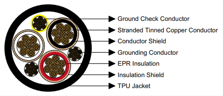
Industrial-grade SHD-GC three-conductor portable power cable with TPU jacket rated 8kV. ICEA S-75-381 compliant for draglines, shovels, dredges, drilling equipment. EPR insulation, tinned copper conductors, 4 AWG to 500 kcmil configurations available.
SHD-GC Three-Conductor Round Portable Power Cable with Thermoplastic Polyurethane Jacket – 8kV Rating
TYPE: SHD-GC | VOLTAGE: 8000VIndustrial-grade portable power transmission solution engineered for extreme-duty mobile machinery operations. The SHD-GC series represents advanced cable technology specifically manufactured for heavy equipment requiring consistent high-voltage power delivery in demanding operational environments including surface mining, marine dredging, and large-scale excavation projects.
Primary Applications and Operational Environment
This heavy-duty cable configuration has been engineered specifically for mobile industrial equipment that demands reliable high-voltage power transmission under continuous mechanical stress and environmental exposure. The cable construction supports the following equipment categories:
- Dragline Excavators: Power supply systems for large walking draglines used in open-pit mining operations, providing flexible power routing for bucket movement and hoisting mechanisms
- Power Shovels: Primary electrical feed for electric rope shovels and hydraulic excavators operating in mining and quarrying applications
- Dredging Equipment: Marine and inland waterway dredging machinery including cutter suction dredgers, trailing suction hopper dredgers, and bucket dredgers
- Drilling Machinery: Rotary drilling rigs, blast hole drills, and exploration drilling equipment requiring portable high-voltage connections
- Mobile Power Distribution: Temporary power feeders for construction sites, mining camps, and industrial facilities requiring relocatable electrical infrastructure
Manufacturing Standards and Compliance Certifications
The SHD-GC cable series is manufactured in strict accordance with multiple internationally recognized industrial standards, ensuring compatibility with global equipment specifications and safety requirements:
- ICEA S-75-381 / NEMA WC 58: Insulated Cable Engineers Association and National Electrical Manufacturers Association standards for portable and power feeder cables for mining applications
- ASTM B 172: Standard specification for rope-lay-stranded copper conductors having bunch-stranded members, for electrical conductors
- ASTM B 33: Standard specification for tinned soft or annealed copper wire for electrical purposes
- CAN/CSA C22.2 No. 96: Canadian Standards Association requirements for portable power cables
Technical Construction and Material Specifications
Conductor Assembly
The primary current-carrying element consists of high-purity annealed copper strands with tin coating. The stranded configuration provides enhanced flexibility while maintaining low electrical resistance. Tinning prevents oxidation and ensures long-term conductivity stability in humid or corrosive environments. Conductor sizes range from 4 AWG through 500 kcmil, accommodating current requirements from 122 amperes to 536 amperes at standard operating conditions.
Conductor Shielding Layer
A semiconducting polymeric compound is extruded directly over the conductor surface. This conducting layer serves multiple critical functions: it provides a smooth interface with the insulation, eliminates air voids that could cause corona discharge, distributes electrical stress evenly across the insulation system, and maintains consistent capacitance throughout the cable length.
Primary Insulation System
Ethylene Propylene Rubber (EPR) compound forms the main dielectric barrier. EPR offers exceptional electrical properties including high dielectric strength, low dielectric constant, and minimal power factor. The material exhibits outstanding resistance to thermal aging, ozone exposure, moisture ingress, and chemical contamination. Nominal insulation thickness is precisely controlled at 0.150 inches (3.8mm) to ensure proper voltage withstand capability at the 8kV rating.
Insulation Shielding Assembly
A dual-component shielding system is applied over the EPR insulation. The first element is a semiconducting tape that maintains electrical contact with the insulation surface, confining the electrical field within the insulation layer. Over this, a tinned copper and textile composite braid provides mechanical protection, acts as an equipotential surface, and serves as a low-impedance fault current path. This braid construction also facilitates ground fault detection and ensures personnel safety.
Ground Check Conductor
An independent monitoring conductor constructed from tinned copper strands is included within the cable assembly. This conductor is insulated with yellow polypropylene for easy identification. The ground check conductor enables continuous monitoring of ground connection integrity throughout the cable length, providing advance warning of insulation degradation or mechanical damage that could compromise safety systems.
Primary Grounding Conductor
A separate full-size grounding conductor consisting of tinned copper strands runs alongside the insulated phase conductors. This conductor maintains chassis ground connection and provides the primary fault current return path. The conductor sizing is proportional to the phase conductor ampacity, ensuring adequate fault current capacity.
Outer Jacket Material
The cable assembly is enclosed in a Thermoplastic Polyurethane (TPU) jacket extruded to provide complete environmental protection. TPU was selected for its unique combination of properties: excellent abrasion resistance exceeding traditional rubber compounds, superior cut and tear resistance, outstanding flexibility retention at low temperatures, resistance to oils and solvents, and high tensile strength. The black pigmented compound includes UV stabilizers for outdoor applications. Nominal jacket thickness ranges from 0.205 to 0.295 inches (5.2 to 7.5mm) depending on cable size.
Available Customization Options
Alternative Jacket Compounds: For specialized operating conditions, alternative elastomeric jacket materials can be supplied. Options include Chlorinated Polyethylene (CPE) for enhanced weather resistance, Chlorosulfonated Polyethylene (CSP) for chemical environments, Polychloroprene (PCP/Neoprene) for moderate oil resistance, Nitrile Butadiene Rubber (NBR) for superior petroleum product resistance, and standard Polyvinyl Chloride (PVC) for cost-sensitive applications with moderate performance requirements.
Reinforced Construction: A dual-layer jacket configuration with reinforcing textile fiber between inner and outer jacket layers can be manufactured for applications requiring enhanced mechanical protection. This construction significantly increases resistance to dragging damage, improves cut-through resistance, and extends cable service life in abrasive environments.
Physical and Thermal Operating Parameters
Minimum Bending Radius During Installation: Eight times the overall cable diameter. This specification ensures the cable can be routed around equipment without damaging internal components or creating excessive mechanical stress in the conductor or insulation systems.
Maximum Continuous Conductor Operating Temperature: 90°C (194°F). This temperature rating represents the maximum sustained conductor temperature under normal load conditions. The EPR insulation system is thermally rated for continuous operation at this temperature without degradation of electrical or mechanical properties.
Ambient Operating Temperature Range: The cable remains flexible and operational in ambient temperatures from -40°C to +60°C. The TPU jacket maintains flexibility at cold temperatures while the EPR insulation withstands elevated temperatures without softening or deformation.
Complete Dimensional and Electrical Specifications
The following table provides comprehensive technical data for all standard cable configurations. Conductor sizes are specified using American Wire Gauge (AWG) for smaller sizes and circular mil notation (kcmil) for larger sizes. Current ratings are calculated based on conductor temperature of 90°C and ambient air temperature of 40°C, following ICEA S-75-381 methodology.
| Cable Configuration | Stranding Count | Ground Conductor | Check Conductor | Insulation Thickness | Jacket Thickness | Overall Diameter | Cable Weight | Current Rating |
|---|---|---|---|---|---|---|---|---|
| (Cores × Size) | (Number) | (AWG/kcmil) | (AWG) | inch (mm) | inch (mm) | inch (mm) | lbs/kft (kg/km) | (Amperes) |
| 3 × 4 AWG | 259 | 8 AWG | 8 AWG | 0.150 (3.8) | 0.205 (5.2) | 1.94 (49.3) | 2019 (3004) | 122 |
| 3 × 2 AWG | 259 | 6 AWG | 8 AWG | 0.150 (3.8) | 0.220 (5.6) | 2.12 (53.8) | 2603 (3873) | 159 |
| 3 × 1 AWG | 259 | 5 AWG | 8 AWG | 0.150 (3.8) | 0.220 (5.6) | 2.21 (56.1) | 2913 (4334) | 184 |
| 3 × 1/0 AWG | 266 | 4 AWG | 8 AWG | 0.150 (3.8) | 0.220 (5.6) | 2.32 (58.9) | 3351 (4986) | 211 |
| 3 × 2/0 AWG | 323 | 3 AWG | 8 AWG | 0.150 (3.8) | 0.235 (6.0) | 2.46 (62.5) | 3946 (5871) | 243 |
| 3 × 3/0 AWG | 418 | 2 AWG | 8 AWG | 0.150 (3.8) | 0.250 (6.4) | 2.62 (66.5) | 4582 (6817) | 279 |
| 3 × 4/0 AWG | 532 | 1 AWG | 8 AWG | 0.150 (3.8) | 0.250 (6.4) | 2.75 (69.8) | 5321 (7917) | 321 |
| 3 × 250 kcmil | 627 | 1/0 AWG | 6 AWG | 0.150 (3.8) | 0.250 (6.4) | 2.89 (73.4) | 6101 (9077) | 355 |
| 3 × 350 kcmil | 888 | 2/0 AWG | 6 AWG | 0.150 (3.8) | 0.280 (7.1) | 3.21 (81.3) | 7696 (11450) | 435 |
| 3 × 500 kcmil | 1221 | 4/0 AWG | 6 AWG | 0.150 (3.8) | 0.295 (7.5) | 3.56 (90.4) | 10199 (15174) | 536 |
Cable Size Selection and Performance Comparison
Proper cable size selection requires consideration of multiple factors including required current capacity, voltage drop limitations, mechanical flexibility requirements, and installation space constraints. The following comparison highlights key differences across size ranges:
Small Diameter Range (4 AWG – 1 AWG)
- Current Capacity: 122A to 184A
- Flexibility: Highest flexibility, minimum 15.5-inch bend radius
- Weight: Lightest option, 2019-2913 lbs per 1000 feet
- Typical Use: Auxiliary equipment, smaller mobile machines, temporary connections
- Installation: Easiest to handle and route through confined spaces
Medium Diameter Range (1/0 AWG – 4/0 AWG)
- Current Capacity: 211A to 321A
- Flexibility: Good flexibility, 18.6-22 inch bend radius
- Weight: Moderate weight, 3351-5321 lbs per 1000 feet
- Typical Use: Standard mining equipment, medium power shovels, moderate-size draglines
- Installation: Balanced between flexibility and current capacity
Large Diameter Range (250 kcmil – 500 kcmil)
- Current Capacity: 355A to 536A
- Flexibility: Reduced flexibility, 23.1-28.5 inch bend radius
- Weight: Heaviest construction, 6101-10199 lbs per 1000 feet
- Typical Use: Large draglines, major dredging operations, high-power mobile equipment
- Installation: Requires mechanical handling equipment
Installation Recommendations and Service Considerations
Proper installation and maintenance practices are essential for maximizing cable service life and ensuring safe operation. During installation, cables should be stored on reels and protected from direct sunlight and moisture. When pulling cable, tension should be applied to the conductors rather than the jacket whenever possible, and maximum pulling tension should not exceed conductor tensile strength specifications. Sharp bends must be avoided, maintaining the minimum eight times diameter bend radius at all points. Cable supports should be positioned to prevent excessive sag while avoiding compression damage. Regular visual inspections should check for jacket cuts, abrasions, or deformation, and electrical testing should verify insulation resistance periodically. Any damaged sections must be immediately removed from service and properly repaired or replaced by qualified personnel.
Technical Support and Quotations
Our engineering team provides comprehensive application support including cable selection guidance, custom specification development, and installation planning assistance. Contact us for detailed quotations, custom configurations, or technical consultation.
Email: [email protected] | Tel: +86 13855123218


