ZPMC Port Crane Maintenance & Refurbishment: Complete Technical Guide
ZPMC Port Crane Maintenance & Refurbishment: Complete Technical Guide
🎯 Key Takeaways
This comprehensive guide covers essential maintenance and refurbishment procedures for ZPMC port cranes, with detailed focus on festoon cable systems that power modern port automation. Learn about critical safety standards, material specifications, and proven troubleshooting techniques to maximize crane performance and minimize downtime.
📑 Table of Contents
- 1. Introduction to ZPMC Port Cranes
- 2. Essential Maintenance & Refurbishment Steps
- 3. Festoon Cable Systems: Purpose & Function
- 4. Cable Characteristics & Specifications
- 5. Material Structure & Construction
- 6. Compliance Standards & Certifications
- 7. Safety Thresholds & Requirements
- 8. Precautions for Use
- 9. Common Problems & Solutions
Introduction to ZPMC Port Cranes
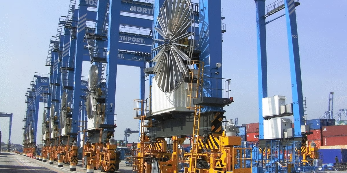
Shanghai Zhenhua Heavy Industries Co., Ltd. (ZPMC) stands as the world’s leading port container crane manufacturer, commanding over 82% of the global market share for port equipment. With operations spanning more than 100 countries and over 30,000 employees worldwide, ZPMC has established itself as the premier supplier of Ship-to-Shore (STS) cranes, Rubber Tyred Gantry (RTG) cranes, Rail Mounted Gantry (RMG) cranes, and Automated Stacking Cranes (ASC).
Modern port operations demand increasingly sophisticated automation and electrification systems. As vessels continue to grow in size and cargo volumes increase, port operators face mounting pressure to upgrade existing equipment while maintaining operational efficiency. This has positioned ZPMC not only as the world’s largest crane manufacturer but also as the number one provider of crane upgrade and refurbishment services globally.
Market Leadership: ZPMC controls 92% of the US port equipment market and 80% of the European market, with major installations at Rotterdam, Hamburg, Shanghai, Hong Kong, Singapore, Dubai, and ports throughout North America.
Essential Maintenance & Refurbishment Steps for ZPMC Port Cranes
Strategic Maintenance Framework
Proper maintenance and refurbishment of ZPMC port cranes require a systematic approach that addresses mechanical, electrical, and structural components. The following procedures represent industry best practices for maintaining optimal crane performance.
1Comprehensive Condition Assessment
Initial Inspection Protocol
- Visual Structural Inspection: Examine main girders, boom structures, portal frames, and A-frames for deformation, cracks, corrosion, or welding defects
- Electrical System Evaluation: Test all motors, drives, control panels, sensors, and safety systems for proper operation and wear patterns
- Mechanical Component Analysis: Assess brakes, gearboxes, couplings, bearings, wheels, and rails for wear, alignment issues, and operational efficiency
- Wire Rope & Hoisting Systems: Check for birdcaging, corrosion, abrasion, fatigue breaks, core protrusion, and diameter reduction
- Electrification System Review: Inspect conductor bars, festoon cables, cable reels, and all power distribution components
2Crane Heightening & Boom Extension Projects
To accommodate increasingly larger vessels, many ports require crane heightening projects. ZPMC has developed specialized jacking systems and engineering expertise to raise cranes by 5-10 meters while maintaining operational safety.
- Temporary relocation to construction site for major modifications
- Structural reinforcement and additional boom sections installation
- Recalibration of hoisting systems and counterweight adjustments
- Extension of power supply and control cable systems
- Complete electrical drive upgrades to handle increased loads
3Electrical System Modernization
Critical Upgrade Components
- Drive System Conversion: Upgrade from DC to modern AC variable frequency drives (VFD) for improved energy efficiency and control precision
- Automation Integration: Install advanced monitoring systems, sensors, and programmable logic controllers (PLCs) for semi-automated or fully automated operations
- LED Lighting Systems: Replace conventional lighting with energy-efficient LED arrays for improved visibility and reduced power consumption
- Cable Reel & Festoon Upgrades: Install new spreader cable reel systems and modernize festoon electrification infrastructure
- Safety System Enhancement: Implement advanced anti-collision systems, load monitoring, and emergency shutdown protocols
4Mechanical Refurbishment
Mechanical components endure extreme operational stresses and require systematic renewal to prevent catastrophic failures.
- Bearing Replacement: Replace all critical bearings showing signs of wear, overheating, or contamination
- Gearbox Overhaul: Rebuild or replace gearboxes, ensuring proper lubrication and seal integrity
- Brake System Restoration: Replace brake pads, drums, hydraulic components, and calibrate braking torque
- Wheel & Rail Maintenance: Address wheel flange wear, replace damaged wheels, and ensure proper rail alignment within CMAA tolerances
- Structural Steel Repairs: Repair or reinforce cracked welds, corroded sections, and deformed structural members
5Preventive Maintenance Schedule
| Interval | Maintenance Activities | Critical Focus Areas |
|---|---|---|
| Daily/Shift | Visual inspections, operational tests | Wire ropes, brakes, hooks, control systems, festoon cables |
| Weekly | Lubrication, minor adjustments | Bearings, gearboxes, cable trolleys, rail surfaces |
| Monthly | Detailed component inspection | Electrical connections, cable wear, structural integrity |
| Quarterly | System calibration, testing | Load cells, safety devices, alignment verification |
| Annual | Comprehensive overhaul planning | Major component renewal, system upgrades, compliance audit |
6Documentation & Compliance
- Maintain detailed service records and inspection logs
- Ensure compliance with OSHA 1910.179, CMAA specifications, and local regulations
- Document all modifications, parts replacements, and upgrade projects
- Conduct load testing after major refurbishment activities
- Implement digital monitoring systems for real-time condition assessment
Festoon Cable Systems: Purpose & Function in Crane Electrification
Understanding Crane Electrification
Festoon cable systems represent one of three primary electrification methods for overhead and gantry cranes, alongside conductor bars and cable reels. The electrification system serves as the critical lifeline delivering power and control signals to moving crane components, enabling precise load handling operations.
Primary Functions of Festoon Cables
Core Operational Purposes
- Power Transmission: Deliver single-phase or three-phase electrical power (typically 400-690V AC) to crane hoists, trolleys, and auxiliary equipment during continuous motion
- Control Signal Communication: Transmit low-voltage control signals (24-110V) for contactors, limit switches, position sensors, and programmable logic controllers
- Bridge Connection: Establish the electrical link between stationary power bars on the runway and moving crane bridge or trolley systems
- Data & Communication: Support fiber optic and Ethernet cables for modern automation systems, remote monitoring, and predictive maintenance platforms
- Auxiliary Systems Support: Power lighting systems, operator cabin equipment, safety devices, and environmental monitoring sensors
Why Festoon Systems for Port Cranes?
Port crane applications demand festoon systems for specific operational advantages:
- Environmental Resilience: Exceptional performance in harsh maritime environments with salt spray, moisture, UV exposure, and extreme temperature fluctuations (-40°C to +105°C)
- High-Speed Capability: Support for motorized festoon trolleys operating at speeds up to 240 meters per minute in automated STS crane applications
- Long Travel Distances: Effective power delivery over extended runway lengths (50-100+ meters) common in large container terminals
- Multiple Cable Management: Organize and protect numerous power, control, and data cables simultaneously without twisting or tangling
- Maintenance Accessibility: Easier inspection and cable replacement compared to enclosed conductor systems, reducing downtime
Port Application Excellence: Festoon systems are the preferred electrification method for ZPMC ship-to-shore cranes, automated stacking cranes, and rubber-tyred gantry cranes due to their reliability in continuous-flex applications and ability to handle the demanding marine environment found in global port facilities.
Cable Characteristics & Technical Specifications
Design Philosophy for Port Crane Applications
Festoon cables for ZPMC port cranes are engineered with specialized characteristics to withstand millions of flex cycles, environmental extremes, and mechanical stresses unique to maritime cargo handling operations.
Critical Technical Characteristics
Electrical Performance
- Voltage Rating: 0.6/1 kV (600V/1000V) for power cables; 300V-450V for control cables
- Current Carrying Capacity: Determined by VDE 0298-4 standards for continuous operation in festoon systems
- Conductor Size Range: 14 AWG to 4/0 AWG (2.5mm² to 120mm² cross-section) depending on application
- Number of Conductors: 2 to 61 conductors in single cable assembly
- Conductor Class: Class 5 or Class 6 fine-stranded tinned copper for maximum flexibility and corrosion resistance
Mechanical Properties
- Flexibility Factor: Engineered for minimum bend radius of 10-15 times cable outer diameter
- Flex Life: Rated for 5-10 million flex cycles under specified conditions
- Tensile Strength: Reinforced construction to withstand cable weight and dynamic forces during high-speed travel
- Abrasion Resistance: Specialized outer jacket compounds resist wear from trolley contact and environmental factors
- Torsion Resistance: Tightened internal cable structure prevents twisting and maintains circular cross-section
Cable Configuration Types
| Type | Construction | Primary Application |
|---|---|---|
| Flat Festoon Cable | Parallel conductors in flat profile | Space-constrained indoor crane systems, RTG cranes |
| Round Festoon Cable | Concentric or bundled round construction | Outdoor STS cranes, heavy-duty port applications |
| Hybrid Cable | Power + control + fiber optic combined | Automated cranes requiring integrated communication |
| Specialty High-Flex | Advanced polymer insulation, extra-fine stranding | High-speed motorized festoon systems (200+ m/min) |
Environmental Performance Characteristics
- Temperature Range: -40°C to +105°C continuous operation; -50°C to +120°C short-term exposure
- Weather Resistance: UV stabilized compounds resist sunlight degradation over decades of outdoor exposure
- Chemical Resistance: Resistant to oils, greases, mild acids, alkalis, and salt water exposure
- Moisture Protection: Water-resistant or waterproof constructions for marine environments
- Fire Performance: Flame-retardant compounds meeting IEC 60332-3 vertical flame test requirements
⚠️ Critical Specification Warning: Never substitute standard industrial cables for festoon applications. Standard cables lack the fine-stranded conductors, specialized insulation compounds, and reinforced construction required for continuous-flex service. Using improper cables will result in premature failure, safety hazards, and costly operational downtime.
Material Structure & Construction Details
Layer-by-Layer Construction Analysis
Premium festoon cables for ZPMC port cranes employ sophisticated multi-layer construction, with each component optimized for specific performance requirements.
Conductor Core (Inner Layer)
Conductor Specifications
- Material: 99.9% pure electrolytic copper with tin plating (tinned copper)
- Stranding Class: Class 5 (flexible) or Class 6 (extra-flexible) per IEC 60228 / VDE 0295
- Wire Count: 150-2,000+ individual wire strands depending on conductor size and flexibility requirements
- Tin Plating Benefits: Prevents oxidation, improves solderability, enhances corrosion resistance in marine environments
- Compaction: Compressed strand construction reduces overall diameter while maintaining flexibility
Insulation Layer (Primary Electrical Protection)
| Material Type | Properties | Best Application |
|---|---|---|
| EPR (Ethylene Propylene Rubber) | Excellent flexibility, weather resistance, thermal range -40°C to +90°C | Standard port crane applications, outdoor use |
| EPDM (Modified EPR) | Enhanced ozone/UV resistance, superior aging characteristics | Long-life installations in harsh maritime climates |
| PBT (Polybutylene Terephthalate) | Very high flexibility, chemical resistance, -50°C to +105°C | High-speed festoon systems, extreme temperature environments |
| Modified TPE (Thermoplastic Elastomer) | Exceptional flex life, low temperature performance | Arctic port operations, ultra-high-cycle applications |
Inner Sheath / Bedding Layer
Specialized intermediate layer that:
- Separates and protects individual insulated conductors from mechanical damage
- Maintains cable geometry during flexing to prevent conductor migration
- Provides additional electrical isolation and moisture barrier
- Typically constructed from EVA (Ethylene Vinyl Acetate) or thermoplastic elastomer compounds
Reinforcement & Structural Elements
Advanced Reinforcement Options
- Aramid Yarn (Kevlar) Reinforcement: High tensile strength fibers prevent cable elongation under its own weight during vertical festoon applications
- Steel Wire Braid: Provides crush resistance and additional mechanical protection for extreme heavy-duty applications
- Textile Braid: Enhances tear resistance and provides substrate for outer jacket adhesion
- Fleece Wrapping: Cushions individual conductors and facilitates smooth relative movement during flexing
Outer Jacket (Protective Sheath)
The final protective layer is critical for long-term survival in port environments:
Jacket Material Specifications
- 5GM3 Compound: Special rubber mixture providing excellent abrasion, weather, and chemical resistance per VDE specifications
- 5GM5 Enhanced Compound: Superior mechanical properties for the most demanding applications
- TPU (Thermoplastic Polyurethane): Outstanding abrasion resistance, flexibility retention at low temperatures
- Neoprene (Polychloroprene): Traditional marine-grade material with proven long-term outdoor performance
- Color Options: Typically black (UV-stabilized with carbon black); yellow for high-visibility safety applications
- Surface Texture: Smooth or ribbed finish; ribbed surface improves trolley grip and reduces festoon cable slippage
Material Innovation: Leading manufacturers like TRATOS have developed specialized TRATOSFESTOON compound with tightened internal structure that grants exceptional strength, reduced outer diameter (critical for festoon trolley compatibility), and extended service life under severe operating conditions in over 300 ports worldwide.
Compliance Standards & International Certifications
Regulatory Framework for Crane Cables
Festoon cables for ZPMC port cranes must comply with multiple international standards governing electrical safety, mechanical performance, environmental characteristics, and fire protection. Compliance ensures interoperability, safety, and legal operation across global port facilities.
Primary International Standards
VDE (Verband der Elektrotechnik) Standards – Germany
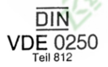
- VDE 0250-813/814: Flexible cables for special applications including festoon systems; defines construction, materials, and testing requirements
- VDE 0298-4: Current carrying capacity calculations for festoon cable systems in continuous operation
- VDE 0472-804: Fire performance testing for bunched cables
- VDE 0295: Conductor classification and flexibility standards
IEC (International Electrotechnical Commission) Standards
- IEC 60204-32: Safety of machinery – Electrical equipment of machines for hoisting and handling applications
- IEC 60228: Conductors of insulated cables – standardizes conductor classes and materials
- IEC 60332-3: Flame propagation test for cables in vertical configuration (bunched cable test)
- IEC 60811: Insulation and sheath materials testing methods
- IEC 61537: Cable management systems for electrical installations
North American Standards & Compliance
| Standard | Jurisdiction | Requirements |
|---|---|---|
| UL 1581 | USA (Underwriters Laboratories) | Reference standard for electrical wires, cables, and flexible cords testing |
| CSA C22.2 | Canada | Canadian electrical code requirements for industrial cables |
| OSHA 1910.179 | USA (Occupational Safety) | Overhead and gantry crane electrical equipment requirements, voltage limits, wiring specifications |
| NEC Article 610 | USA (National Electrical Code) | Cranes and hoists electrical installation requirements |
European Directives & CE Marking
- Low Voltage Directive (LVD) 2014/35/EU: Safety requirements for electrical equipment operating between 50-1000V AC
- Machinery Directive 2006/42/EC: Essential health and safety requirements for machinery including cranes
- RoHS Directive 2011/65/EU: Restriction of hazardous substances; limits lead, mercury, cadmium in cable materials
- CPR (Construction Products Regulation) EN 50575: Fire classification for cables (Eca, Cca, B2ca classes)
Industry-Specific Standards
CMAA (Crane Manufacturers Association of America)
- CMAA Specification #70: Specifications for top running bridge and gantry type multiple girder electric overhead traveling cranes
- CMAA #74: Specifications for top running and under running single girder electric overhead traveling cranes
- Defines tolerance requirements for runway systems, electrical equipment specifications, and maintenance protocols
Certification & Testing Requirements
Manufacturers must obtain third-party certification demonstrating compliance:
- VDE Testing Mark: Internationally recognized certification from VDE Testing and Certification Institute (Frankfurt, Germany)
- UL Listed: Underwriters Laboratories certification for North American markets
- CE Mark: Declaration of conformity with European Union directives
- Type Testing: Comprehensive testing including electrical properties, mechanical endurance, environmental resistance, fire performance
- Quality Management: ISO 9001 certified manufacturing processes
⚠️ Compliance Critical: Using non-compliant cables violates safety regulations, voids insurance coverage, and exposes port operators to legal liability. Always verify that festoon cables bear appropriate certification marks (VDE, UL, CE) and request certification documents from suppliers before installation.
Safety Thresholds & Operational Requirements
Electrical Safety Parameters
Voltage & Current Safety Limits
- Maximum Operating Voltage: 600V AC / 750V DC for control circuits per OSHA 1910.179
- Pendant Control Voltage: Must not exceed 150V AC for operator safety (typically 24-110V in modern systems)
- Current Capacity Margins: Cable ampacity must exceed maximum load current by minimum 25% safety factor
- Leakage Current: Insulation resistance must maintain >1 MΩ at operating voltage to prevent shock hazards
- Ground Continuity: Equipment grounding conductor required; resistance <1 Ω from crane to earth ground
Fire Safety & Thermal Protection
| Parameter | Threshold | Safety Rationale |
|---|---|---|
| Maximum Conductor Temperature | 90°C continuous / 120°C emergency | Prevents insulation degradation and fire initiation |
| Ambient Temperature Range | -40°C to +60°C (cable rated to +105°C) | Ensures adequate thermal margin in extreme port environments |
| Flame Propagation | Pass IEC 60332-3 Category A/B | Prevents fire spread along cable runs |
| Smoke Density | <60% light obscuration (IEC 61034) | Maintains visibility during emergency evacuation |
| Halogen Content | <0.5% by weight (LSOH variants) | Reduces toxic/corrosive gas emission during fire |
Mechanical Safety Thresholds
Load & Stress Limits
- Maximum Bend Radius: Never bend cable tighter than 10x outer diameter during installation; 15x during operation to prevent conductor damage
- Tensile Load Limit: Cable self-weight support reinforcement must handle 3x cable weight as safety factor
- Festoon Trolley Spacing: Maximum 2-3 meter intervals to prevent excessive cable sag and strain
- Stack-Up Prevention: Festoon system length limits based on cable weight and track design to avoid excessive accumulation at end-stops
- Abrasion Resistance: Outer jacket must withstand minimum 5,000 cycles in DIN abrasion test without conductor exposure
Environmental Protection Requirements
- IP Rating: Cable glands and connections must achieve minimum IP54 (dust protected, splash resistant); IP65+ for exposed marine environments
- Corrosion Protection: Tinned copper conductors prevent galvanic corrosion in salt-spray environments
- UV Stabilization: Outdoor cables must retain >80% mechanical properties after 2,000 hours UV exposure testing
- Chemical Resistance: Jacket materials must resist degradation from oils, hydraulic fluids, and mild industrial chemicals per IEC 60811-404
Safety System Integration
Critical Safety Requirements
- Emergency Stop Circuits: Hardwired E-stop must function independently of primary control cables
- Overload Protection: Circuit breakers and thermal overload relays properly sized for cable ampacity
- Ground Fault Detection: GFCI protection recommended for portable/mobile crane applications
- Arc Flash Labeling: Electrical panels must display arc flash hazard warnings per NFPA 70E
- Lockout/Tagout: Disconnect switches accessible and lockable per OSHA 1910.147
- Inspection Intervals: Daily visual checks; monthly electrical testing; annual comprehensive assessment
Personnel Safety Protocols
- Only qualified electricians may install, maintain, or repair festoon cable systems
- De-energize all circuits and verify zero voltage before maintenance work
- Use insulated tools and personal protective equipment (PPE) rated for voltage level
- Implement arc flash protection measures for high-current circuits (>100A)
- Ensure proper training on specific crane electrical systems and emergency procedures
- Establish restricted access zones around energized festoon systems during operation
Precautions for Installation, Operation & Maintenance
Installation Best Practices
Pre-Installation Planning
- System Design Verification: Confirm festoon track type (C-track, I-beam, square rail, wire rope) matches cable specifications and environmental conditions
- Cable Route Survey: Verify no sharp edges, pinch points, or obstructions along entire festoon travel path
- Load Calculations: Calculate total cable weight and ensure trolley/track system rated for combined load plus 50% safety margin
- Environmental Assessment: Evaluate temperature extremes, chemical exposures, UV intensity, and select cable specifications accordingly
Critical Installation Precautions
⚠️ Installation Warnings – Failure Results in Premature Cable Damage
- NEVER Exceed Minimum Bend Radius: Over-bending during installation creates permanent conductor damage invisible from exterior inspection
- PREVENT Cable Twisting: Maintain cable orientation throughout installation; twisted cables will fail rapidly in festoon service
- AVOID Dragging Cables: Use cable rollers or manual support; dragging over rough surfaces damages jacket and introduces contaminants
- TEMPERATURE Control: Install cables at ambient temperature 15-25°C; cold cables become stiff and prone to installation damage
- TORQUE Specifications: Follow manufacturer torque values for cable glands and terminals; over-tightening crushes conductors
Proper Cable Support & Trolley Configuration
- Install festoon trolleys at regular intervals per manufacturer specifications (typically every 1.5-3.0 meters)
- Ensure trolley wheels rotate freely and track surfaces are smooth, clean, and properly aligned
- Use appropriate cable clamps that distribute pressure evenly without crushing cable structure
- Maintain adequate working clearances: minimum 100mm from cable to obstacles during full travel
- Balance cable weight distribution across all trolleys to prevent uneven wear
Operational Precautions
Daily Pre-Operation Checks
- Visually inspect cables for cuts, abrasions, crushing, or jacket damage
- Check festoon trolleys for smooth rolling action; listen for unusual noises indicating binding or misalignment
- Verify cable hangs in proper festoon loops without excessive sag or tension
- Confirm no cable stack-up at end-stops; adjust trolley spacing if necessary
- Test emergency stop and safety systems before energizing crane for production use
Preventing Common Operational Issues
| Issue | Prevention Measures |
|---|---|
| Cable Twisting | Ensure proper trolley clamp installation; verify cable feeds from same orientation throughout system; use swivel connections if necessary |
| Excessive Sagging | Add intermediate trolley supports; verify cable weight within system capacity; check for trolley binding causing uneven distribution |
| Abrasion Wear | Eliminate contact with sharp edges; maintain proper trolley wheel alignment; replace worn trolley wheels promptly |
| Environmental Damage | Select cables with appropriate jacket materials; implement protective covers in areas with chemical exposure; clean accumulated contaminants monthly |
| Overheating | Verify cable ampacity adequate for actual load; improve ventilation around cable runs; reduce duty cycle if operating near thermal limits |
Maintenance Precautions
- Electrical Isolation: Always de-energize and lockout/tagout power sources before any maintenance activity
- Voltage Verification: Test with calibrated multimeter to confirm zero voltage at all conductors before touching cables
- Inspection Documentation: Record all findings, measurements, and maintenance actions in crane logbook
- Cleaning Methods: Use mild detergent and water only; avoid solvents that may damage jacket materials
- Replacement Parts: Use only manufacturer-specified cables; “equivalent” substitutes often lack critical specifications
Special Precautions for Automated Systems
High-Speed Festoon Systems: Automated STS cranes operating at 180-240 m/min require specialized high-flex cables and motorized festoon trolleys. These systems demand:
- Monthly lubrication of trolley bearings and track surfaces
- Weekly verification of trolley motor operation and synchronization
- Fiber optic continuity testing for communication cables (OTDR testing quarterly)
- Vibration monitoring to detect developing mechanical issues
- Immediate investigation of any unusual cable movement patterns
Storage & Handling Precautions
- Store cable reels indoors or under waterproof covers to prevent moisture absorption
- Maintain storage temperature between 0-35°C to prevent insulation degradation
- Rotate cable reels quarterly to prevent flat-spotting during long-term storage
- Protect cable ends from contamination with sealed caps or wrapping
- Label cables clearly with specifications, installation date, and inspection status
Common Problems, Root Causes & Troubleshooting Solutions
Cable Failure Analysis Framework
Festoon cable failures in port crane applications typically result from mechanical stress, environmental factors, electrical overload, or improper installation/maintenance. Understanding failure modes enables proactive prevention and rapid troubleshooting.
Problem 1: Conductor Breakage & Fatigue Failures
Symptoms
- Intermittent loss of power or control signals during crane operation
- Complete circuit failure requiring cable replacement
- Visible strand breakage when cable flexed at typical service locations
- Increased electrical resistance measurements compared to baseline values
Root Causes
- Excessive Bending: Operating below minimum bend radius specification causes conductor fatigue and crystallization
- Vibration Fatigue: Millions of flex cycles eventually cause work-hardening and breakage even in properly installed systems
- Improper Cable Selection: Using insufficient conductor class (Class 2 instead of Class 5/6) for festoon application
- Tension Overload: Cable supporting excessive weight due to inadequate trolley spacing or reinforcement
Solutions
- Replace failed cable with proper festoon-rated cable having Class 5 or 6 stranded conductors
- Verify and increase festoon trolley support points to reduce unsupported cable spans
- Check all pulley and guide radii; replace any components causing tight bends
- Implement predictive maintenance: measure conductor resistance quarterly to detect developing failures
- Consider upgrading to higher-flex specialty cables for high-cycle applications (>5 million cycles)
Problem 2: Jacket Damage & Insulation Breakdown
Symptoms
- Visible cracks, cuts, or abrasion through outer jacket exposing inner layers
- Insulation resistance testing shows values below 1 MΩ threshold
- Ground fault circuit interrupters tripping during operation
- Electrical arcing or tracking visible on cable surface during wet conditions
Root Causes
- Mechanical Abrasion: Cable rubbing against festoon trolley edges, track components, or crane structure
- Environmental Degradation: UV exposure, ozone, extreme temperatures, or chemical attack weakening jacket materials
- Improper Installation: Sharp edges along cable path cutting into jacket during movement
- Impact Damage: Cables struck by cargo, equipment, or maintenance activities
Solutions
- Immediately replace cables with compromised insulation integrity to prevent shock hazards
- Identify and eliminate all sharp edges, burrs, or rough surfaces along festoon path
- Verify trolley wheels properly aligned and rotating freely; replace worn wheels
- Install protective cable guides or covers in areas prone to impact or abrasion
- Upgrade to cables with enhanced jacket materials (5GM5, TPU) for severe environments
- Implement protective maintenance: clean and inspect cables monthly; apply approved protective coatings if recommended by manufacturer
Problem 3: Cable Twisting & Core Protrusion
| Symptom | Root Cause | Solution |
|---|---|---|
| Cable develops spiral twist pattern; conductors visible protruding from jacket; reduced service life | Improper trolley clamp installation allowing cable rotation; torque introduced during installation; wrong cable type for application | Replace damaged cable; reinstall with proper trolley clamps preventing rotation; verify cable designed for torsion resistance; add swivel connections if necessary |
Problem 4: Overheating & Thermal Damage
Symptoms & Causes
- Symptom: Discolored, brittle, or melted insulation; thermal trip of circuit protection devices
- Cause 1 – Undersized Cable: Current draw exceeds cable ampacity specification
- Cause 2 – Poor Connections: High-resistance terminations generating heat at contact points
- Cause 3 – Ventilation Issues: Cable bundles preventing heat dissipation; excessive ambient temperature
- Cause 4 – Overloading: Crane operating beyond rated capacity increasing motor current
Solutions
- Verify cable size adequate for actual load using VDE 0298-4 current capacity tables
- Inspect all terminations; clean and re-torque connections to specification
- Upgrade to larger conductor size if operating near thermal limits
- Improve cable spacing and ventilation; consider forced air cooling for enclosed festoon tracks
- Install thermal monitoring systems for early warning of overheating conditions
Problem 5: Environmental & Corrosion Damage
Port Environment Challenges
- Salt Spray Corrosion: Conductors and connections corrode in marine environment despite cable jacketing
- UV Degradation: Jacket becomes brittle and cracks after years of sun exposure
- Chemical Attack: Cargo residues (oils, acids, fertilizers) degrade cable materials
- Moisture Ingress: Water penetrates damaged jacket causing internal corrosion and electrical leakage
Prevention & Solutions
- Specify cables with tinned copper conductors for corrosion resistance in all port applications
- Select jacket materials with proven UV stability (carbon black loaded compounds, UV stabilizers)
- Use sealed cable glands rated IP65 or higher at all termination points
- Implement monthly cleaning protocol removing salt deposits and contaminants
- Apply dielectric grease to connections to prevent moisture-induced corrosion
- Consider protective conduit or covers for cables in areas with severe chemical exposure
- Plan for lifecycle replacement: even best cables degrade after 10-15 years in harsh marine environments
Problem 6: Festoon System Mechanical Failures
| Problem | Symptoms | Troubleshooting Steps |
|---|---|---|
| Trolley Binding | Jerky cable movement; uneven festoon loops; noise during crane travel | Inspect trolley wheels for damage; clean track surfaces; verify track alignment; lubricate wheel bearings; replace worn components |
| Cable Stack-Up | Cable accumulation at end-stop preventing full crane travel; cable damage from compression | Add intermediate trolleys to reduce unsupported spans; verify track length adequate; check for binding trolleys preventing proper retraction |
| Excessive Sagging | Cable droops below festoon track; risk of snagging on obstacles | Increase number of support trolleys; verify cable weight within system rating; check for broken trolley wheels; ensure proper cable clamp installation |
| Motorized System Failure | Automated festoon not tracking crane movement; cable tension issues | Test trolley drive motors; verify encoder feedback signals; check control system programming; inspect power supply to motorized trolleys |
Diagnostic Tools & Testing Methods
Essential Testing Equipment
- Megohmmeter (Megger): 500V or 1000V insulation resistance tester for detecting insulation breakdown
- Digital Multimeter: Measure conductor resistance, continuity, and voltage drop under load
- Thermal Imaging Camera: Identify hot spots indicating high-resistance connections or overloading
- OTDR (Optical Time Domain Reflectometer): Test fiber optic cables in hybrid festoon systems
- Hi-Pot Tester: Verify dielectric strength for new installations or after repairs
Troubleshooting Decision Tree
Quick Diagnostic Process
- Safety First: De-energize and lockout system before investigation
- Visual Inspection: Examine entire cable length for obvious damage, wear, or misalignment
- Electrical Testing: Measure insulation resistance and conductor continuity
- Mechanical Assessment: Check trolley operation, track condition, and cable support
- Environmental Review: Consider recent exposure to extreme temperatures, chemicals, or impacts
- Historical Analysis: Review maintenance records for recurring problems or service patterns
- Root Cause Determination: Identify underlying cause, not just symptom, to prevent recurrence
- Corrective Action: Repair or replace damaged components; address root cause
- Preventive Measures: Implement monitoring or design changes to prevent future failures
When to Replace vs. Repair
⚠️ Critical Replacement Criteria – DO NOT ATTEMPT REPAIR:
- Any conductor breakage visible or detected through resistance testing
- Insulation resistance below 1 MΩ at operating voltage
- Jacket damage exposing conductors or inner insulation layers
- Evidence of overheating (discolored, melted, or brittle insulation)
- Cables operating beyond design flex life (typically 5-10 million cycles)
- Multiple repair splices (spliced cables unsuitable for festoon flexing applications)
- Unknown cable history or specifications
Replace entire cable length rather than splice repairs. Festoon applications cannot tolerate the mechanical discontinuities and reduced flexibility introduced by field splicing.