
An engineering guide to the YCY construction: a PVC inner sheath, a tinned copper braid of approx. 85 % coverage and a transparent PVC outer sheath, built for interference-free data and signal transmission in fixed laying and free-movement applications without tensile stress.
ÖPVC-JB/OB-YCY: screened PVC power, control and connecting cable, 0.5–185 mm²
An engineering guide to the YCY construction: a PVC inner sheath, a tinned copper braid of approx. 85 % coverage and a transparent PVC outer sheath, built for interference-free data and signal transmission in fixed laying and free-movement applications without tensile stress.
1. Reading the designation
In the German cable code, Y denotes PVC and C a copper screen. Read from the inside out, Y-C-Y means PVC inner sheath, copper braid, PVC outer sheath. JB identifies versions with a green/yellow protective conductor (shown as ‘G’ in the dimension tables) and OB versions without it (shown as ‘x’). The voltage class changes with cross-section: up to 16 mm² the cable is rated 300/500 V; from 25 mm² it carries 1 kV insulation walls and is rated 0.6/1 kV.
Standard sizes, from 2 × 0.5 mm² to 4 G 185 mm².
Optical coverage of the tinned copper braid.
Test voltage on every length.
Minimum insulation resistance.
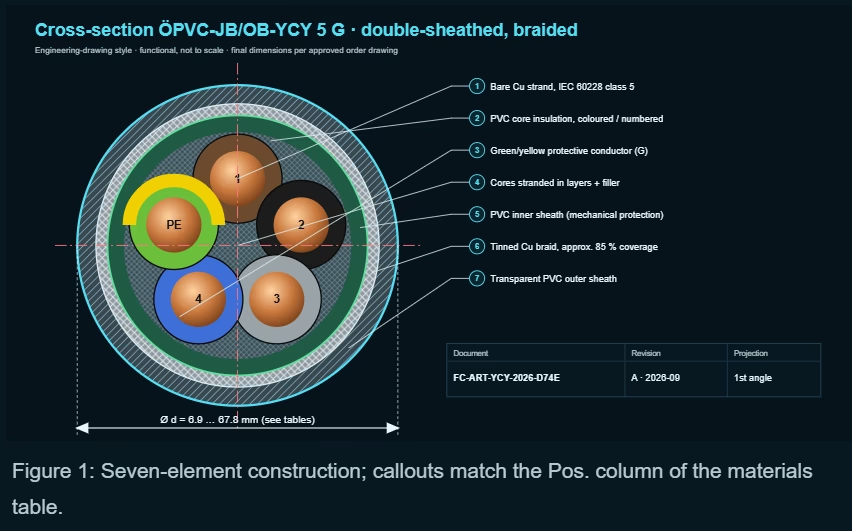
2. Construction
The inner sheath is what separates this design from a standard CY cable. In a single-sheathed CY, the braid bears directly on the core insulation: every impact or tight bend is transferred straight through the braid wires into the PVC. In YCY, the inner sheath acts as a cushion, keeps the braid round, so its coverage stays uniform, and gives a second barrier against moisture and chemicals.
| Pos. | Element | Material / form | Engineering function |
|---|---|---|---|
| 1 | Conductor | Bare Cu, fine-wire, IEC 60228 cl. 5 | Flexibility for installation and free movement |
| 2 | Core insulation | PVC; 1 kV wall thickness on 0.6/1 kV type | Dielectric; +70 °C continuous, +150 °C short-circuit |
| 3 | Protective conductor | GNYE core in ‘G’ versions | PE continuity within the same sheath |
| 4 | Core assembly | Cores stranded in layers | Round, stable geometry under the braid |
| 5 | Inner sheath | PVC | Separates cores from braid; absorbs impact; keeps braid round |
| 6 | Screen | Tinned Cu braid, approx. 85 % optical coverage | EMC screening; tinning resists corrosion and eases soldering |
| 7 | Outer sheath | Transparent PVC | Flame-retardant IEC 60332-1; braid visible for inspection |
3. Technical data
| Parameter | Value | Engineering note |
|---|---|---|
| Conductor material | Bare copper strand | Plain annealed Cu, fine-wire |
| Conductor class | IEC 60228 class 5 | Flexible; resistance values per IEC 60228 cl. 5 |
| Core insulation | PVC | Wall thickness for 1 kV on the 0.6/1 kV type |
| Core identification | Up to 5 cores: DIN VDE 0293-308; from 6 cores: colour code per technical guideline; G = with GNYE | ‘G’ = with green/yellow protective conductor; ‘x’ (or ‘;’ in source tables) = without |
| Stranding | Cores stranded in layers | Layer lay gives round, stable core for braid application |
| Inner sheath | PVC | Additional mechanical protection; bedding for the braid |
| Overall screen | Tinned copper braid, optical coverage approx. 85 % | EMC-compliant shielding |
| Outer sheath | PVC, transparent | Braid visible for inspection of damage and termination quality |
| Rated voltage U0/U | Up to 16 mm²: 300/500 V; from 25 mm²: 0.6/1 kV | |
| Test voltage | 4 kV | |
| Insulation resistance | Min. 20 MΩ × km | |
| Current carrying capacity | Acc. to DIN VDE (see technical guideline) | Apply grouping and ambient derating |
| Min. bending radius fixed | 6 × d | |
| Min. bending radius moved | 15 × d | Free movement only |
| Operating temp. fixed | −40 °C / +80 °C | |
| Operating temp. moved | −15 °C / +70 °C | |
| Conductor temperature | +70 °C in operation; +150 °C short-circuit | |
| Burning behaviour | Self-extinguishing and flame-retardant acc. to IEC 60332-1 | Single-cable test; not a bunched-cable (IEC 60332-3) rating |
| Standard | Similar to EN 50525-2-51; 0.6/1 kV type with 1 kV insulation thickness | |
| Chemical resistance | Largely resistant to acids, bases and specified types of oil | Confirm specific media on request |
| Compliance | RoHS; 2014/35/EU Low Voltage Directive (CE); LABS-/silicone-free during production |
4. Full dimension and weight tables
Bending radii in the two right-hand columns are calculated from the nominal outer diameter (6 × d fixed, 15 × d moved) to save the designer a step. Cu index is the copper mass used for metal surcharge calculation.
| Dimension n × mm² | Reference item no. | U0/U | Outer Ø mm | Cu index kg/km | Weight kg/km | Min. bend radius fixed (6 × d) mm | Min. bend radius moved (15 × d) mm |
|---|---|---|---|---|---|---|---|
| 2 x 0.5 | 1000982 | 300/500 V | 6.9 | 41.0 | 74.0 | 41 | 104 |
| 3 G 0.5 | 1000395 | 300/500 V | 7.3 | 46.0 | 78.0 | 44 | 110 |
| 4 G 0.5 | 1000403 | 300/500 V | 7.9 | 55.0 | 95.0 | 47 | 118 |
| 5 G 0.5 | 1000412 | 300/500 V | 8.4 | 66.0 | 111.0 | 50 | 126 |
| 2 x 0.75 | 1000985 | 300/500 V | 7.5 | 46.0 | 77.0 | 45 | 112 |
| 3 G 0.75 | 1000396 | 300/500 V | 7.9 | 58.0 | 91.0 | 47 | 118 |
| 4 G 0.75 | 1000404 | 300/500 V | 8.4 | 64.0 | 109.0 | 50 | 126 |
| 5 G 0.75 | 1000413 | 300/500 V | 9.1 | 77.0 | 136.0 | 55 | 136 |
| 2 x 1 | 1000987 | 300/500 V | 7.9 | 56.0 | 91.0 | 47 | 118 |
| 3 G 1 | 1000397 | 300/500 V | 8.2 | 65.0 | 107.0 | 49 | 123 |
| 4 G 1 | 1000405 | 300/500 V | 8.8 | 78.0 | 137.0 | 53 | 132 |
| 5 G 1 | 1000644 | 300/500 V | 9.6 | 89.0 | 164.0 | 58 | 144 |
| 2 x 1.5 | 1000988 | 300/500 V | 8.7 | 65.0 | 115.0 | 52 | 130 |
| 3 G 1.5 | 1000398 | 300/500 V | 9.0 | 83.0 | 137.0 | 54 | 135 |
| 4 G 1.5 | 1000406 | 300/500 V | 9.7 | 100.0 | 173.0 | 58 | 146 |
| 5 G 1.5 | 1000414 | 300/500 V | 10.6 | 125.0 | 210.0 | 64 | 159 |
| 3 G 2.5 | 1000401 | 300/500 V | 10.5 | 146.0 | 210.0 | 63 | 158 |
| 4 G 2.5 | 1000407 | 300/500 V | 11.5 | 167.0 | 267.0 | 69 | 172 |
| 5 G 2.5 | 1000420 | 300/500 V | 12.5 | 200.0 | 319.0 | 75 | 188 |
| 4 G 4 | 1001861 | 300/500 V | 13.7 | 237.0 | 369.0 | 82 | 206 |
| 5 G 4 | 1000421 | 300/500 V | 15.3 | 280.0 | 446.0 | 92 | 230 |
| 4 G 6 | 1000409 | 300/500 V | 16.1 | 318.0 | 503.0 | 97 | 242 |
| 5 G 6 | 1000422 | 300/500 V | 17.3 | 441.0 | 611.0 | 104 | 260 |
| 4 G 10 | 1001862 | 300/500 V | 19.4 | 558.0 | 764.0 | 116 | 291 |
| 5 G 10 | 1000417 | 300/500 V | 21.8 | 714.0 | 943.0 | 131 | 327 |
| 4 G 16 | 1001879 | 300/500 V | 22.6 | 804.0 | 1,080.0 | 136 | 339 |
| 5 G 16 | 1000418 | 300/500 V | 25.2 | 1,053.0 | 1,325.0 | 151 | 378 |
| Dimension n × mm² | Reference item no. | U0/U | Outer Ø mm | Cu index kg/km | Weight kg/km | Min. bend radius fixed (6 × d) mm | Min. bend radius moved (15 × d) mm |
|---|---|---|---|---|---|---|---|
| 4 G 25 | 1001880 | 0.6/1 kV | 28.9 | 1,289.0 | 1,624.0 | 173 | 434 |
| 5 G 25 | 1001687 | 0.6/1 kV | 31.8 | 1,446.0 | 2,270.0 | 191 | 477 |
| 4 G 35 | 1001768 | 0.6/1 kV | 32.2 | 1,680.0 | 2,135.0 | 193 | 483 |
| 5 G 35 | 1001776 | 0.6/1 kV | 36.4 | 1,975.0 | 2,771.0 | 218 | 546 |
| 4 G 50 | 1000408 | 0.6/1 kV | 38.8 | 2,342.0 | 3,362.0 | 233 | 582 |
| 4 G 70 | 1000410 | 0.6/1 kV | 43.7 | 3,103.0 | 4,320.0 | 262 | 656 |
| 4 G 95 | 1000411 | 0.6/1 kV | 50.4 | 4,055.0 | 5,849.0 | 302 | 756 |
| 4 G 120 | 1001604 | 0.6/1 kV | 56.8 | 5,225.0 | 7,509.0 | 341 | 852 |
| 4 G 150 | 1003392 | 0.6/1 kV | 62.2 | 6,300.0 | 7,800.0 | 373 | 933 |
| 4 G 185 | 1003393 | 0.6/1 kV | 67.8 | 7,753.0 | 9,866.0 | 407 | 1017 |
5. EMC: why termination beats coverage
A braid of about 85 % optical coverage gives a low transfer impedance across the frequency range typical of variable-speed drive switching noise. In practice, however, measured screening performance is usually limited by the termination rather than the braid itself. A twisted pigtail a few centimetres long adds enough inductance to lose most of the high-frequency benefit.
6. Application envelope
The cable is used as a power, control and connecting cable in electrical facilities, for interference-free data and signal transmission, in fixed laying and in flexible applications with free movement, without tensile stress and without forced guidance. It suits dry, humid and wet rooms. Outdoor use requires UV protection, and it must not be laid underground.
7. Comparison with other types
| Type | Screen | Sheath | Key characteristic | Typical use |
|---|---|---|---|---|
| YY (PVC/PVC, unscreened) | None | Single sheath | Lowest cost; no EMC | Fixed and light flexible, no noise sources |
| CY / YCY single-sheath (PVC-CY) | Tinned Cu braid | Braid directly under outer sheath | Thinner, lighter | Standard screened control |
| ÖPVC-JB/OB-YCY | Tinned Cu braid approx. 85 % | PVC inner sheath + PVC outer | Braid protected, cores protected from braid | Industrial power/control with EMC and mechanical demand |
| PUR chain cable (screened) | Tinned Cu braid, high coverage | TPE/PUR | Millions of cycles | Drag chains, robots |
| NYCWY (0.6/1 kV) | Concentric Cu wires | PVC | Concentric conductor, burial-rated | Fixed power distribution, underground |
8. Design calculations
9. Certification and traceability
FeiChun Cable holds a complete export certification portfolio — including CE, UKCA, VDE, EAC, ATEX and IECEx — and this cable is produced RoHS-conform, conforming to the 2014/35/EU Low Voltage Directive, and LABS-/silicone-free during production. Every certificate supplied is checked against the exact type, voltage, factory and standard of the order: a certificate name is never a substitute for its scope.
Routine tests
Conductor resistance to IEC 60228 cl. 5, 4 kV voltage test, insulation resistance, braid continuity, dimensions and marking.
Type tests
IEC 60332-1 flame propagation, sheath properties before and after ageing, cold behaviour, oil resistance on request.
Delivery documents
Approved datasheet and drawing, test report per drum, batch number and length marking.
10. FAQ
Why a transparent outer sheath?
The tinned braid remains visible, so crushed or opened braid areas and incorrect terminations can be spotted during inspection.
Is 85 % coverage enough for VSD motor leads?
For typical industrial drives, yes, provided the braid is bonded 360° at both ends via EMC glands. Coverage matters less than termination quality.
What do ‘G’ and ‘x’ mean?
‘G’ includes a green/yellow protective conductor; ‘x’ (shown as ‘;’ in some source tables) has no GNYE core.
Can I use it in a drag chain?
No. It is rated for free movement without tensile stress or forced guidance. Choose a chain-rated PUR/TPE screened cable.
Why does voltage change at 25 mm²?
From 25 mm² the cable uses 1 kV insulation wall thickness and is rated 0.6/1 kV; up to 16 mm² it follows the 300/500 V EN 50525-2-51 approach.
Can it be buried or used outdoors?
Not buried. Outdoors only with UV protection (conduit, cover or UV-rated tray cover).
Technical and project enquiries: [email protected]
+86 13855123218


