
Comprehensive Technical Guide to Medium Voltage Reeling Cables with Integrated Fiber Optics for Mining Applications
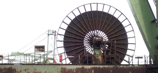
What is a Type NTSCGEWÖU 3,6/6 – 12/20 kV Highly Flexible Mining Reeling Cable?
Comprehensive Technical Guide to Medium Voltage Reeling Cables with Integrated Fiber Optics for Mining Applications
The NTSCGEWÖU cable represents a sophisticated engineering solution designed specifically for demanding mining and heavy industrial environments. This highly flexible medium voltage reeling cable integrates advanced fiber optic technology with robust electrical conductors, making it ideal for applications requiring simultaneous power transmission and high-speed data communication in extreme operating conditions.
Manufactured in compliance with the stringent DIN VDE 0250 Part 813 standard, this cable is engineered to withstand the harsh realities of underground mining operations, including severe mechanical stresses, extreme temperatures, chemical exposure, and continuous flexing cycles inherent to reeling applications.
1. Purpose and Applications
Primary Purpose
The NTSCGEWÖU cable serves as a comprehensive power and communication solution for mobile heavy machinery in mining environments. Its primary function is to deliver reliable electrical power while simultaneously providing fiber optic communication channels for real-time monitoring, control systems, and data transmission.
Typical Applications
This cable type is specifically engineered for use in the following demanding applications:
- Mobile Mining Equipment: Large-scale excavators, dragline systems, bucket-wheel excavators, and mobile crushers in open-pit mining operations
- Container Handling: Automated stacking cranes (ASCs), rail-mounted gantry cranes (RMGs), and rubber-tired gantry cranes (RTGs) in container terminals and ports
- Underground Mining: Continuous miners, longwall shearers, and shuttle cars in coal and ore mining applications
- Material Handling: High-capacity conveyor systems, ship loaders, and reclaimers in bulk material handling facilities
- Heavy Industry: Steel mills, foundries, and large-scale manufacturing equipment requiring mobile power distribution
Key Application Advantages
The integrated fiber optic technology enables advanced monitoring capabilities including vibration analysis, temperature sensing, and real-time equipment diagnostics, significantly improving operational safety and equipment uptime in critical mining operations.
Environmental Suitability
According to VDE 0250 Part 813 specifications, these cables are designed for installation in diverse environmental conditions including dry, moist, and wet indoor and outdoor locations, as well as areas with explosion hazards where proper certification is maintained.
2. Key Characteristics
Mechanical Properties
Extreme Flexibility
Conductor Construction: Class 5 VDE 0295 (IEC 60228)
Special construction design provides superior flexibility beyond standard requirements
High Tensile Strength
Maximum Tensile Load: 20 N/mm²
Calculated on total phase conductor cross-section
Torsional Resistance
Maximum Torsional Stress: ±25°/m
Withstands multi-plane deflection and continuous twisting
High-Speed Reeling
Maximum Working Speed: 120 m/min
Suitable for high-speed reeling and unreeling operations
Thermal Characteristics
| Parameter | Value | Notes |
|---|---|---|
| Maximum Working Temperature | 90°C | Continuous operation on conductor |
| Short Circuit Temperature | 250°C | Maximum permissible during fault conditions |
| Ambient Temperature (Mobile) | -25°C to +80°C | During operation with movement |
| Ambient Temperature (Static) | -40°C to +80°C | When cable is not in motion |
Chemical and Environmental Resistance
- Flame Retardancy: Complies with IEC 60332-1-2 standards for flame propagation resistance
- Oil Resistance: Tested according to IEC 60811-2-1, suitable for environments with hydraulic oils and lubricants
- Ozone Resistance: Superior resistance to ozone degradation per IEC 60811-2-1
- Weather Resistance: Suitable for both indoor and outdoor applications with UV stability
- Chemical Resistance: Chloroprene rubber outer sheath provides excellent resistance to acids, alkalis, and industrial chemicals
Fiber Optic Capabilities
The integrated fiber optic system provides high-bandwidth communication capabilities essential for modern industrial automation:
| Fiber Type | Configuration | Attenuation | Bandwidth | Transmission Distance |
|---|---|---|---|---|
| 50/125 Multimode | 6-24 fibers | ≤2.5 dB/km @ 850nm | ≥200 MHz·km | Up to 2 km |
| 62.5/125 Multimode | 6-24 fibers | ≤3.0 dB/km @ 850nm | ≥200 MHz·km | Up to 2 km |
| 9/125 Singlemode | 4-24 fibers | ≤0.35 dB/km @ 1310nm | N/A (high bandwidth) | Up to 120 km without relay |
3. Material Structure and Construction
Layer-by-Layer Construction
The NTSCGEWÖU cable features a sophisticated multi-layer construction designed to optimize electrical performance, mechanical strength, and flexibility:
1. Phase Conductors
- Material: Tinned annealed copper
- Construction: Class 5 flexible stranded per VDE 0295 (IEC 60228) with special enhanced flexibility construction
- Tinning Purpose: Provides superior corrosion resistance and improved solderability in harsh mining environments
- Semiconductive Layer: Semiconductive tape applied over conductor
2. Phase Insulation System
- Material: 3GI3 quality ethylene-propylene rubber (EPR) compound according to VDE 0207 Part 20
- Thickness: According to VDE 0250 Part 813 Table 1 specifications
- Semiconductive Layers: Inner and outer semiconductive rubber layers extruded in single pass with insulation (triple extrusion process)
- Purpose: Provides electrical field control and stress distribution, critical for medium voltage applications
3. Earth (Ground) Conductors
- Material: Tinned copper
- Construction: Class 5 VDE 0295 flexible stranded
- Configuration: Split into 2 parts for balanced mechanical protection
- Covering: Semiconductive layer for electrical integrity
4. Fiber Optic Core Assembly
- Transmission Media: 50/125, 62.5/125 multimode or 9/125 singlemode optical fibers
- Nominal Aperture: 250 μm precision glass fiber
- Fiber Count Options: 6, 8, 12, or 24 fibers (multimode); 4, 6, 8, 12, or 24 fibers (singlemode)
- Protection: Special rubber compound covering over twisted fiber cores
- Arrangement: Optimized to minimize stress during cable flexing and torsion
5. Central Filler
- Material: Semiconductive compound on textile polyester support
- Function: Maintains cable roundness, provides mechanical support, and ensures proper spacing of twisted cores
6. Core Assembly
- Configuration: Twisted power cores with earth conductors split into 2 parts, integrated with fiber optic bundle
- Separator: Semiconductive tape wound on twisted core assembly
- Design Philosophy: Optimized lay length to minimize stress concentration during bending and twisting
7. Inner Sheath
- Material: 5GM3 quality rubber compound according to VDE 0207 Part 21
- Thickness: According to VDE 0250 Part 813 Table 2 specifications
- Function: Provides mechanical protection for inner cores and serves as barrier against moisture and contaminants
8. Anti-Twisting Element
- Material: High-strength polyester braid
- Position: Between inner and outer sheath
- Critical Function: Prevents cable rotation during reeling operations, maintaining dimensional stability under torsional loads of ±25°/m
9. Outer Sheath
- Material: 5GM5 quality chloroprene rubber compound according to VDE 0207 Part 21
- Thickness: According to VDE 0250 Part 813 Table 2 specifications
- Properties: Superior abrasion resistance, tear resistance, oil resistance, flame retardancy, and weatherability
- Color: Typically black with identification markings
Manufacturing Excellence
The triple extrusion process for the insulation and semiconductive layers is a critical manufacturing technique that ensures uniform electrical field distribution and eliminates potential void formation between layers. This process, combined with the integrated anti-twisting polyester braid, distinguishes premium mining cables from standard flexible power cables.
4. Compliance with Standards
Primary Certification
DIN VDE 0250 Part 813 Approved
This cable is manufactured in strict accordance with DIN VDE 0250 Part 813, the German national standard specifically governing flexible trailing cables for power installations in mining and heavy industrial applications. This standard is recognized globally as the benchmark for reeling cable performance and safety.
Applicable International Standards
| Standard | Specification | Application |
|---|---|---|
| VDE 0295 | IEC 60228 | Conductors of insulated cables – defines Class 5 flexible conductor construction |
| VDE 0207 Part 20 | — | 3GI3 quality insulation compound specifications |
| VDE 0207 Part 21 | — | 5GM3 and 5GM5 quality rubber sheath compound specifications |
| VDE 0298 Part 3 | — | Minimum bending radius requirements |
| VDE 0298 Part 4 | — | Current rating calculations and ampacity determination |
| IEC 60332-1-2 | — | Tests on electric and optical fiber cables under fire conditions – flame retardancy |
| IEC 60811-2-1 | — | Common test methods for insulating and sheathing materials – oil and ozone resistance |
| HD 620 S2 | — | Harmonized distribution cables of rated voltage 0.6/1 kV (European harmonization) |
Quality Assurance and Testing
Each cable undergoes comprehensive testing to ensure compliance with specifications:
- Reeling Test: Specialized dynamic testing simulating actual reeling operations under specified tensile loads and bending cycles
- Voltage Test: High potential (Hi-Pot) testing at specified test voltages ranging from 11 kV to 29 kV depending on rated voltage
- Insulation Resistance: Measurement per VDE standards to ensure electrical integrity
- Flame Test: IEC 60332-1-2 vertical flame propagation test
- Mechanical Tests: Tensile strength, elongation, and tear resistance testing on insulation and sheath materials
- Environmental Tests: Oil immersion, ozone exposure, and thermal aging tests per IEC 60811-2-1
- Optical Tests: Attenuation measurement at specified wavelengths and bandwidth verification for fiber optic cores
5. Safety Thresholds and Operating Parameters
Electrical Safety Parameters
Available Voltage Ratings
System 1: 3,6/6 kV
- Rated Voltage U₀/U: 3.6/6 kV
- Test Voltage: 11 kV
- Maximum AC Operating Voltage: 4.2/7.2 kV
- Typical Application: Medium-scale mining equipment, auxiliary systems
System 2: 6/10 kV
- Rated Voltage U₀/U: 6/10 kV
- Test Voltage: 17 kV
- Maximum AC Operating Voltage: 6.9/12 kV
- Typical Application: Large draglines, bucket-wheel excavators
System 3: 8,7/15 kV
- Rated Voltage U₀/U: 8.7/15 kV
- Test Voltage: 24 kV
- Maximum AC Operating Voltage: 10.4/18 kV
- Typical Application: High-capacity material handling systems
System 4: 12/20 kV
- Rated Voltage U₀/U: 12/20 kV
- Test Voltage: 29 kV
- Maximum AC Operating Voltage: 13.9/24 kV
- Typical Application: Large-scale mobile mining equipment, high-power applications
Current Carrying Capacity
Current ratings are calculated according to VDE 0298 Part 4 and depend on multiple factors:
- Conductor cross-sectional area (25 mm² to 150 mm² for phase conductors)
- Installation method (drum reeling vs. free-hanging)
- Ambient temperature (standard reference: 30°C)
- Number of loaded conductors
- Grouping and spacing of cables
⚠ Critical Safety Warning
Research by the U.S. Bureau of Mines Pittsburgh Research Center has demonstrated that under static test conditions, electrical current levels permitted under standard regulations may not adequately limit cable temperatures to below the 90°C rating for reeled trailing cables. Continuous temperature monitoring is essential for reeled installations to prevent thermal damage and ensure operational safety.
Mechanical Safety Limits
| Parameter | Maximum Value | Safety Consideration |
|---|---|---|
| Tensile Load | 20 N/mm² (on conductor area) | Exceeding this value may cause conductor damage or insulation stress |
| Bending Radius | Per VDE 0298 Part 3 | Minimum radius varies by cable diameter; typically 10-15× outer diameter |
| Torsional Stress | ±25°/m | Exceeding causes internal conductor stress and fiber optic signal degradation |
| Reeling Speed | 120 m/min | Higher speeds increase mechanical stress and thermal buildup |
Environmental Operating Envelopes
- Mobile Operation Temperature Range: -25°C to +80°C (cable in motion during operation)
- Static Storage Temperature Range: -40°C to +80°C (cable stationary or stored)
- Humidity: Suitable for dry, moist, and wet environments
- Altitude: Standard ratings apply up to 1000m; derating required for higher elevations
Short Circuit Protection
The cable is designed to withstand short circuit temperatures up to 250°C for limited duration (typically 5 seconds per IEC standards). Protective devices must be sized to clear faults within this timeframe to prevent permanent cable damage.
Electrical Field Control
The triple-extruded semiconductive layer system provides superior electrical field control, eliminating surface discharge and corona formation at voltage stress points. This is critical for reliability in medium voltage applications where partial discharge can lead to premature insulation failure.
6. Precautions for Use
Installation Precautions
Critical Installation Requirements
- Minimum Bending Radius: Never bend the cable below the minimum radius specified in VDE 0298 Part 3 (typically 10-15 times the outer cable diameter). Excessive bending causes permanent damage to conductors and fiber optics.
- Pulling Force: Do not exceed 20 N/mm² calculated on the total phase conductor cross-section during installation pulls.
- Twisting Prevention: Use appropriate cable support systems and drum configurations to prevent excessive twisting beyond ±25°/m specification.
- Drum Winding: Ensure proper drum diameter ratio and avoid crossovers or overlapping layers that can cause crushing damage.
Storage and Handling
- Storage Temperature: Store cables in ambient conditions between -40°C and +80°C when not in use
- UV Protection: While the outer sheath provides UV resistance, prolonged exposure to direct sunlight should be minimized during storage
- Chemical Exposure: Avoid storage near corrosive chemicals, solvents, or substances that may attack rubber compounds
- Mechanical Protection: Protect cable ends with appropriate sealing caps to prevent moisture ingress and contamination
- Drum Storage: Store cable drums on flat surfaces to prevent deformation; rotate drums periodically if stored for extended periods
Operational Precautions
Electrical Safety
- Qualified Personnel: Installation, termination, and maintenance must be performed only by qualified electrical personnel familiar with medium voltage systems
- De-energization: Always verify complete de-energization and implement lockout/tagout procedures before working on cables
- Grounding: Ensure proper connection of earth conductors according to applicable electrical codes and standards
- Insulation Testing: Perform insulation resistance testing before initial energization and periodically during service life
- Termination Quality: Use only approved termination kits and follow manufacturer specifications precisely to maintain electrical field control
Mechanical Operation
- Regular Inspection: Implement scheduled visual inspections for outer sheath damage, cuts, abrasions, or chemical attack
- Tensile Load Monitoring: Install load monitoring systems on mobile equipment to prevent exceeding rated tensile strength
- Speed Limits: Do not exceed the maximum reeling speed of 120 m/min to prevent excessive dynamic stresses
- Multi-Plane Bending: While designed for multi-plane deflection, minimize unnecessary complex bending patterns that accelerate wear
- Cable Guides: Ensure proper alignment and functioning of cable guide systems to prevent abrasion and localized stress concentration
Fiber Optic Considerations
- Laser Safety: Never look directly into fiber optic cable ends when systems are energized; invisible infrared light can cause permanent eye damage
- Cleanliness: Maintain strict cleanliness protocols during fiber optic termination to prevent contamination affecting optical performance
- Bend Radius: Fiber optic cores are particularly sensitive to excessive bending; maintain minimum bend radius at all times
- Testing: Use appropriate optical power meters and OTDR equipment to verify fiber performance after installation and periodically during service
Environmental Considerations
- Explosion Hazard Areas: Ensure appropriate certification and approval for use in classified hazardous locations (mines with gas or dust explosion risk)
- Water Submersion: While suitable for wet conditions, prolonged submersion may require additional protection or special cable variants
- Extreme Temperatures: Monitor cable temperature in extreme ambient conditions; implement cooling periods if conductor temperature approaches 90°C limit
- Chemical Exposure: While the 5GM5 sheath provides excellent chemical resistance, direct contact with strong acids or bases should be avoided
Maintenance Requirements
Preventive Maintenance Schedule
- Daily: Visual inspection for obvious damage during equipment operation
- Weekly: Detailed visual inspection of exposed cable sections, terminations, and connection points
- Monthly: Thermal imaging inspection to identify hot spots indicating overloading or poor connections
- Quarterly: Fiber optic performance testing and documentation
- Annually: Comprehensive insulation resistance testing and mechanical integrity assessment
- Major Overhaul: Complete cable replacement or refurbishment based on usage intensity and inspection findings
7. Common Problems and Solutions
Problem 1: Premature Outer Sheath Wear
Symptoms
Visible abrasion, cuts, or thinning of outer black sheath material, particularly at cable guide points or drum contact areas.
Causes
- Improper alignment of cable guides causing concentrated abrasion
- Contamination with abrasive particles (dirt, sand, coal dust)
- Insufficient drum diameter causing excessive bending stress
- Operating speed exceeding 120 m/min specification
Solutions
- Verify and adjust cable guide alignment and spacing
- Implement regular cleaning protocols for cable surface and guides
- Ensure drum diameter meets minimum specifications per VDE 0298 Part 3
- Install speed monitoring and limiting devices
- Consider upgrading to cables with reinforced outer sheaths for severe conditions
Problem 2: Fiber Optic Signal Degradation
Symptoms
Increased bit error rates, intermittent signal loss, or complete communication failure on fiber optic channels.
Causes
- Excessive bending below minimum radius causing microbending losses
- Excessive torsional stress beyond ±25°/m damaging fiber cores
- Mechanical damage to fiber optic bundle from crush or impact
- Contamination at fiber optic connectors
- Water ingress affecting fiber performance
Solutions
- Use OTDR testing to locate specific fault locations
- Verify installation complies with minimum bending radius requirements
- Inspect and clean all fiber optic connectors using proper procedures
- Check anti-twisting element integrity and drum rotation mechanisms
- Test cable sections for water presence; replace if moisture infiltration detected
- Implement fiber optic performance monitoring systems for early fault detection
Problem 3: Overheating During Operation
Symptoms
Cable surface temperature exceeds normal operating range, thermal imaging shows hot spots, or thermal overload protection trips.
Causes
- Current loading exceeds ampacity rating calculated per VDE 0298 Part 4
- Poor heat dissipation when cable is tightly wound on drum
- High ambient temperature reducing effective cooling
- Damaged or corroded connections increasing resistance
- Improper drum design restricting airflow
Solutions
- Verify actual load current against ampacity ratings for installation method
- Apply derating factors for drum-wound cable and elevated ambient temperatures
- Implement thermal monitoring systems at critical points
- Ensure minimum cable exposure (unwound length) during high-load operations
- Inspect and refurbish all electrical connections
- Consider upgrading to larger conductor cross-section if continuous overload conditions exist
Problem 4: Earth Conductor Failure
Symptoms
Ground fault protection fails to operate correctly, increased electrical noise, or safety hazards during fault conditions.
Causes
- Excessive tensile stress damaging earth conductor strands
- Corrosion of tinned copper earth conductors due to moisture ingress
- Poor termination quality at connection points
- Repeated flexing cycles causing fatigue failure
Solutions
- Perform continuity testing on earth conductors regularly
- Verify tensile loads do not exceed 20 N/mm² specification
- Inspect terminations for proper compression and contact integrity
- Replace cable sections showing elevated earth conductor resistance
- Ensure proper sealing at termination points to prevent moisture ingress
Problem 5: Insulation Degradation
Symptoms
Decreasing insulation resistance measurements, partial discharge activity detected, or ground fault occurrences.
Causes
- Thermal aging from prolonged operation at elevated temperatures
- Moisture ingress through damaged outer sheath
- Chemical attack from incompatible substances
- Mechanical damage to insulation from excessive bending or crushing
- Electrical stress from voltage surges or switching transients
Solutions
- Implement scheduled insulation resistance testing (megger testing)
- Conduct partial discharge testing for early fault detection
- Verify operating temperatures remain within 90°C conductor limit
- Inspect outer sheath integrity and repair minor damage promptly
- Install surge protection devices to limit voltage transients
- Replace cable sections showing degraded insulation resistance values
Problem 6: Cable Twisting and Rotation
Symptoms
Cable exhibits visible spiral deformation, termination stress, or mechanical binding during reeling operations.
Causes
- Failure or damage to anti-twisting polyester braid element
- Improper drum design allowing cable rotation
- Torsional stress exceeding ±25°/m design limit
- Non-symmetrical loading or unbalanced cable construction
Solutions
- Inspect anti-twisting element integrity during major maintenance
- Verify drum design includes anti-rotation features
- Implement torsion monitoring if excessive twisting is observed
- Review cable routing to minimize torsional loads
- Replace cable if anti-twisting element shows significant deterioration
⚠ When to Replace Cable
Cable replacement is mandatory when any of the following conditions are observed:
- Inner conductor layers visible through outer sheath damage
- Insulation resistance below minimum acceptable values per VDE standards
- Partial discharge activity indicating insulation deterioration
- Multiple fiber optic cores showing permanent signal loss
- Visible mechanical deformation or kinking of cable structure
- Earth conductor continuity failure
- Extensive outer sheath cracking or material degradation
Attempting to extend service life of critically damaged cables creates serious safety hazards and can result in catastrophic equipment failure.
8. Detailed Technical Specifications
Cable Dimensions and Weights
The following tables provide comprehensive dimensional and weight specifications for all available voltage ratings and conductor configurations:
3,6/6 kV Configuration
| Configuration | Conductor Ø | Min Overall Ø | Max Overall Ø | Approx Weight | Max Tensile Load |
|---|---|---|---|---|---|
| 3×25 + 2×25/2 + FO | 6.8 mm | 44.7 mm | 47.6 mm | 2,820 kg/km | 1,500 N |
| 3×35 + 2×25/2 + FO | 7.8 mm | 46.6 mm | 49.5 mm | 3,190 kg/km | 2,100 N |
| 3×50 + 2×25/2 + FO | 9.4 mm | 49.9 mm | 52.9 mm | 3,990 kg/km | 3,000 N |
| 3×70 + 2×35/2 + FO | 11.2 mm | 55.5 mm | 58.5 mm | 5,070 kg/km | 4,200 N |
| 3×95 + 2×50/2 + FO | 12.7 mm | 58.9 mm | 61.9 mm | 5,900 kg/km | 5,700 N |
| 3×120 + 2×70/2 + FO | 14.4 mm | 64.4 mm | 68.3 mm | 7,490 kg/km | 7,200 N |
| 3×150 + 2×70/2 + FO | 16.3 mm | 68.5 mm | 72.5 mm | 8,710 kg/km | 9,000 N |
6/10 kV Configuration
| Configuration | Conductor Ø | Min Overall Ø | Max Overall Ø | Approx Weight | Max Tensile Load |
|---|---|---|---|---|---|
| 3×25 + 2×25/2 + FO | 6.8 mm | 47.3 mm | 50.3 mm | 3,370 kg/km | 1,500 N |
| 3×35 + 2×25/2 + FO | 7.8 mm | 48.8 mm | 51.8 mm | 3,730 kg/km | 2,100 N |
| 3×50 + 2×25/2 + FO | 9.4 mm | 53.7 mm | 56.7 mm | 4,680 kg/km | 3,000 N |
| 3×70 + 2×35/2 + FO | 11.2 mm | 57.5 mm | 60.5 mm | 5,770 kg/km | 4,200 N |
| 3×95 + 2×50/2 + FO | 12.7 mm | 60.8 mm | 64.7 mm | 6,720 kg/km | 5,700 N |
| 3×120 + 2×70/2 + FO | 14.4 mm | 66.4 mm | 70.4 mm | 8,280 kg/km | 7,200 N |
8,7/15 kV Configuration
| Configuration | Conductor Ø | Min Overall Ø | Max Overall Ø | Approx Weight | Max Tensile Load |
|---|---|---|---|---|---|
| 3×25 + 2×25/2 + FO | 6.8 mm | 52.0 mm | 55.0 mm | 3,680 kg/km | 1,500 N |
| 3×35 + 2×25/2 + FO | 7.8 mm | 55.2 mm | 58.2 mm | 4,310 kg/km | 2,100 N |
| 3×50 + 2×25/2 + FO | 9.4 mm | 58.4 mm | 61.4 mm | 5,020 kg/km | 3,000 N |
| 3×70 + 2×35/2 + FO | 11.2 mm | 62.1 mm | 66.0 mm | 6,170 kg/km | 4,200 N |
| 3×95 + 2×50/2 + FO | 12.7 mm | 67.2 mm | 71.2 mm | 7,380 kg/km | 5,700 N |
12/20 kV Configuration
| Configuration | Conductor Ø | Min Overall Ø | Max Overall Ø | Approx Weight | Max Tensile Load |
|---|---|---|---|---|---|
| 3×25 + 2×25/2 + FO | 6.8 mm | 58.0 mm | 61.0 mm | 4,490 kg/km | 1,500 N |
| 3×35 + 2×25/2 + FO | 7.8 mm | 59.4 mm | 62.4 mm | 4,830 kg/km | 2,100 N |
| 3×50 + 2×25/2 + FO | 9.4 mm | 64.3 mm | 68.2 mm | 5,840 kg/km | 3,000 N |
| 3×70 + 2×35/2 + FO | 11.2 mm | 68.1 mm | 72.1 mm | 7,030 kg/km | 4,200 N |
Note: Configuration nomenclature indicates: 3 phase conductors × cross-section + 2 earth conductors × cross-section/2 parts + integrated fiber optics (FO)
References and Further Reading
-
DIN VDE 0250-813:1985 – Cables, wires and flexible cords for power installation; trailing cable. Deutsches Institut für Normung (German National Standard).
https://www.vde.com/ -
IEC 60228:2004 – Conductors of insulated cables. International Electrotechnical Commission.
https://www.iec.ch/ -
IEC 60332-1-2:2004 – Tests on electric and optical fibre cables under fire conditions – Test for vertical flame propagation for a single insulated wire or cable. International Electrotechnical Commission.
https://www.iec.ch/ -
VDE 0298-4:2013 – Use of cables and flexible cords in power installations – Part 4: Recommended values for current-carrying capacity. VDE Verlag.
https://www.vde-verlag.de/ -
Eland Cables. (2024). “DIN VDE 0250 Standard Cable.” Technical Documentation.
https://www.elandcables.com/electrical-cable-and-accessories/cables-by-standard/vde0250-cable -
HOC Cable. (2022). “What is Mining Fiber Cable and Its Standard?” Technical Article.
https://www.honecable.com/what-is-mining-fiber-cable-and-its-standard/ -
AFL Global. “White Paper: Benefits of Fiber Optics for Underground Mine Communications.”
https://learn.aflglobal.com/white-papers/fiber-optics-for-underground-mine-communications -
U.S. Bureau of Mines Pittsburgh Research Center. “Research on Trailing Cable Temperature Management in Mining Applications.”
https://stacks.cdc.gov/view/cdc/8659/cdc_8659_DS1.pdf -
OSHA 29 CFR 1910.268 – Telecommunications: Safety regulations for fiber optic installations.
https://www.osha.gov/ -
Corning Inc. “Industrial Network Solutions: Extreme and Harsh Environment Fiber Optic Cable.”
https://www.corning.com/in-building-networks/worldwide/en/home/applications/local-area-networks/harsh-environments.html


