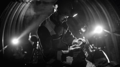
A Comprehensive Technical Guide to Japanese Industrial Standard Flexible Cable Designations for Mining and Industrial Applications
安徽飞纯特种电缆有限公司
What does JIS C 3306 Cable Code Designation mean?
A Comprehensive Technical Guide to Japanese Industrial Standard Flexible Cable Designations for Mining and Industrial Applications
Executive Summary
JIS C 3306 is the Japanese Industrial Standard specification for polyvinyl chloride (PVC) insulated flexible cables (cords) with rated voltages up to and including 300/500V.[1] This standard defines a comprehensive cable designation system used extensively in mining, industrial, and commercial applications worldwide. Understanding these code designations is essential for selecting appropriate cables that ensure safety, reliability, and compliance with international electrical standards.
1. Understanding JIS C 3306 Standard
The JIS C 3306 standard, established by the Japanese Standards Association (JSA), specifies construction requirements, performance characteristics, and testing protocols for PVC-insulated flexible cords.[2] This standard was developed to ensure consistent quality and safety in electrical installations across various industrial sectors, with particular emphasis on applications requiring cable flexibility and durability.
According to the official standard documentation, JIS C 3306:2000 applies to polyvinyl chloride insulated flexible cables operating at rated voltages up to and including 300/500 V.[3] The standard encompasses various cable types designed for different operational environments, from light-duty indoor applications to heavy-duty mining operations. Feichun Cable manufactures a complete range of JIS C 3306 compliant cables for global mining and industrial markets.
1.1 Historical Context and Development
The JIS C 3306 standard has evolved alongside Japan’s electrical industry development, incorporating technological advances in insulation materials, conductor manufacturing, and safety requirements. The standard aligns with international electrical safety protocols while maintaining specifications suited to Asian industrial requirements.
2. JIS C 3306 Cable Code Designation System
The JIS C 3306 cable designation system uses a letter-based nomenclature where each symbol represents specific construction characteristics. Understanding this coding system is critical for engineers, procurement specialists, and mining operators when specifying cables for particular applications.
[H][Material][Core Type][Application Type]
Example: HVCTF = Heat-resistant (H) + PVC insulated (V) + Cabtyre (CT) + Flat (F)
2.1 Symbol Definitions
| Symbol | Meaning | Technical Specification | Application Context |
|---|---|---|---|
| V | Polyvinyl Chloride | PVC insulation compound per JIS C 3005 | Standard temperature applications |
| H | Heat-resistant | Rated for 75°C continuous operation | Elevated temperature environments |
| SF | Single-core Flexible cord | Single conductor construction | Individual power or control circuits |
| TF | Twin-twisted Flexible cord | Two insulated conductors twisted together | Two-wire power or signal applications |
| FF | Flat Flexible cord | Conductors arranged in flat configuration | Space-constrained installations |
| CTF | Cabtyre cord | Heavy-duty flexible construction | Portable equipment and machinery |
| K | Oval shape | Oval cross-sectional geometry | Specific space optimization needs |
2.2 Complete Cable Type Designations
The following table provides comprehensive specifications for all JIS C 3306 cable types, including temperature ratings and typical applications particularly relevant to mining operations:[4]
| Cable Type | Full Description | Rated Temperature | Voltage Rating | Primary Applications |
|---|---|---|---|---|
| VSF | PVC insulated single-core cord | 60°C | 300V | Light-duty portable equipment, indoor wiring |
| HVSF | Heat-resistant PVC insulated single-core cord | 75°C | 300V | Equipment subject to elevated temperatures |
| VTF | PVC insulated twin-twisted cord | 60°C | 300V | Double insulation appliances, small tools |
| HVTF | Heat-resistant PVC insulated twin-twisted cord | 75°C | 300V | Heat-generating equipment connections |
| VFF | PVC insulated flat cord | 60°C | 300V | Under-carpet wiring, confined spaces |
| HVFF | Heat-resistant PVC insulated flat cord | 75°C | 300V | Heated panel connections |
| VCTF | PVC insulated cabtyre round cord | 60°C | 300V | Portable tools, mining equipment, mobile machinery |
| HVCTF | Heat-resistant PVC insulated cabtyre round cord | 75°C | 300V | Mining equipment in high-temperature zones |
| VCTFK | PVC insulated cabtyre oval cord | 60°C | 300V | Space-optimized portable equipment |
| HVCTFK | Heat-resistant PVC insulated cabtyre oval cord | 75°C | 300V | High-temperature constrained installations |
3. Technical Specifications and Material Structure
JIS C 3306 cables are engineered with specific material compositions to ensure reliable performance across diverse operational environments. The material structure directly influences cable performance characteristics including flexibility, temperature resistance, and longevity.[5]
3.1 Conductor Specifications
Class 5 flexibility per IEC 60228, providing optimal balance between conductivity and flexibility
Covers applications from control circuits to moderate power distribution
Enhances flex life and prevents conductor fatigue in mobile applications
At 20°C reference temperature per IEC standards
3.2 Insulation System
The insulation system in JIS C 3306 cables employs specially formulated PVC compounds designed for electrical isolation and mechanical protection. Mining cable applications require insulation materials that maintain integrity under mechanical stress, chemical exposure, and temperature variations encountered in underground and surface mining operations.
| Insulation Parameter | Standard Type (V) | Heat-Resistant Type (HV) | Testing Standard |
|---|---|---|---|
| Maximum Operating Temperature | 60°C | 75°C | JIS C 3005-4.3 |
| Insulation Thickness (0.75mm² conductor) | 0.6 mm | 0.6 mm | JIS C 3306:2000 |
| Insulation Resistance | ≥10 MΩ·km | ≥10 MΩ·km | IEC 60885-1 |
| Dielectric Strength Test Voltage | 1500 VAC (1 min) | 1500 VAC (1 min) | JIS C 3005-4.5 |
| Cold Bend Test Temperature | -15°C | -10°C | JIS C 3005-4.11 |
3.3 Jacket/Sheath Specifications
The outer sheath provides mechanical protection and environmental resistance. According to industry data, cables in mining environments experience abrasion rates 5-10 times higher than standard industrial applications.[6] Reeling cable systems particularly benefit from robust jacket formulations that withstand continuous flexing and external abrasion.
Formulated for abrasion and oil resistance per JIS C 3005
Varies with cable diameter and application severity
Ensures mechanical integrity during installation and operation
Indicates material toughness and flexibility retention
4. Purpose and Applications in Mining Operations
JIS C 3306 cables serve critical functions in mining environments where reliable power distribution is essential for safety and operational continuity. Modern mining operations demand cables that can withstand extreme mechanical stress, chemical exposure, and temperature variations while maintaining electrical integrity.[7]
4.1 Underground Mining Applications
Mining cable specifications for underground operations must account for unique environmental challenges including high humidity (often exceeding 90%), temperatures ranging from 10°C to 40°C, chemical exposure from drilling fluids and mineral processing, and extreme mechanical stress from equipment movement and rock contact.
- Portable Equipment Power Supply: VCTF and HVCTF cables provide reliable power connections for handheld drills, rock bolters, and inspection equipment. The flexible construction allows thousands of bending cycles without conductor fatigue, critical for equipment that moves frequently throughout underground workings.
- Lighting Systems: VSF and HVSF cables supply power to critical underground lighting infrastructure. In coal mines where methane gas presents explosion risks, cable selection must consider not only electrical performance but also flame-resistance characteristics per MSHA standards.[8]
- Ventilation Control Systems: Multi-core VCTF cables connect ventilation fans and monitoring systems that maintain breathable air quality in underground spaces. According to safety regulations, ventilation systems represent life-critical infrastructure requiring the highest reliability standards.
- Communication Networks: Control and signal variants of JIS C 3306 cables facilitate underground communication systems including emergency paging, video monitoring, and wireless network infrastructure essential for modern mining safety protocols.
4.2 Surface Mining and Open-Pit Operations
Surface mining operations expose cables to different but equally challenging conditions. Research indicates that cables in open-pit mines experience temperature variations exceeding 50°C daily, with surface temperatures reaching 60-70°C in arid climates.[9] Crane cable applications in mining require specialized consideration for UV exposure, temperature extremes, and mechanical stress from heavy equipment operations.
| Application | Recommended Cable Type | Key Requirements | Environmental Challenges |
|---|---|---|---|
| Mobile Excavator Power | HVCTF (multi-core) | High flex life, abrasion resistance | Constant movement, rock contact, temperature extremes |
| Conveyor Belt Controls | VCTF (control cable) | Signal integrity, moisture resistance | Dust contamination, vibration, weather exposure |
| Pump Station Power | HVCTF (power cable) | Current capacity, heat resistance | Continuous operation, potential flooding, sediment exposure |
| Haul Truck Charging | HVCTF (heavy-duty) | High current, quick disconnect capability | Frequent connection cycles, diesel fuel exposure, outdoor storage |
5. Compliance with International Standards and Safety Thresholds
Electrical safety in mining operations requires compliance with multiple regulatory frameworks. JIS C 3306 cables designed for mining applications must meet or exceed requirements established by international safety organizations.[10]
5.1 Regulatory Compliance Framework
| Standard/Regulation | Issuing Authority | Scope | Key Requirements |
|---|---|---|---|
| JIS C 3306:2000 | Japanese Standards Association | Basic cable construction and performance | Material specifications, testing protocols, quality assurance |
| JIS C 3662-5 | JSA | Flexible cables rated 450/750V | Enhanced safety margins for industrial applications |
| IEC 60228 | International Electrotechnical Commission | Conductor classification and specifications | Stranding configurations, resistance values, flexibility classes |
| MSHA (US) | Mine Safety and Health Administration | Mining cable flame resistance | Flame propagation limits, toxic fume emission thresholds |
| AS/NZS 1802:2003 | Standards Australia/New Zealand | Mining cables (Australian standard) | Mechanical strength, environmental resistance, electrical performance |
| IEC 60332-3 | IEC | Flame propagation testing | Category C flame test for grouped cables in mining applications |
5.2 Critical Safety Thresholds
⚠️ Critical Safety Parameters
Exceeding these thresholds may result in cable failure, fire hazards, or electrical safety incidents:
- Maximum Continuous Operating Temperature: 60°C (VSF, VTF, VFF, VCTF, VCTFK) or 75°C (HVSF, HVTF, HVFF, HVCTF, HVCTFK). Exceeding these temperatures accelerates insulation degradation and reduces cable service life by approximately 50% for every 10°C increase above rated temperature.[11]
- Emergency Overload Temperature: Not to exceed 100°C for standard types or 110°C for heat-resistant types during fault conditions. Duration limited to 5 seconds maximum per IEC standards.
- Minimum Bending Radius During Installation: 6 × cable outer diameter for fixed installations, 8 × diameter for mobile applications. Violating minimum bend radius causes conductor strand breakage and insulation stress cracking.
- Maximum Voltage Drop: Should not exceed 3% for power circuits or 5% for lighting circuits per IEC 60364-5-52. Excessive voltage drop indicates undersized conductors leading to overheating and potential fire hazards.
- Insulation Resistance Minimum: 10 MΩ·km at 20°C. Values below this threshold indicate insulation deterioration requiring immediate cable replacement. In mining environments, monthly insulation testing is recommended.
5.3 Environmental Operating Limits
Mining cable performance degrades outside specified environmental parameters. Field studies demonstrate that cables operating beyond design limits experience failure rates 3-5 times higher than those within specifications.[12]
Standard operation range; special formulations available for extreme climates
Higher humidity requires enhanced moisture barriers or cable coatings
Outdoor applications require UV-stabilized jacket formulations
Limited resistance to strong solvents and concentrated acids
6. Installation Guidelines and Precautions
Proper installation practices significantly extend cable service life and prevent premature failures. Industry data indicates that approximately 40% of cable failures result from improper installation or handling rather than material defects.[13]
6.1 Pre-Installation Inspection
- Visual Inspection: Examine cable jacket for cuts, abrasions, or deformation. Any visible damage to the outer sheath may indicate compromised insulation integrity requiring rejection before installation.
- Continuity Testing: Verify conductor continuity using a low-resistance ohmmeter. Expected resistance values should align with manufacturer specifications (typically 20-40 Ω/km depending on conductor size).
- Insulation Resistance Testing: Perform megohm testing between conductors and from conductors to ground. Minimum acceptable values: 10 MΩ for new cables, 5 MΩ for cables in service (measured at 500 VDC).
- Environmental Verification: Confirm installation environment temperature, humidity, and exposure conditions match cable rating specifications before proceeding.
6.2 Installation Best Practices
| Installation Aspect | Requirement | Rationale | Consequence of Non-Compliance |
|---|---|---|---|
| Minimum Bend Radius | 6 × OD (fixed), 8 × OD (mobile) | Prevents conductor strand breakage and insulation stress | Premature conductor fatigue, reduced flex life by 50-70% |
| Maximum Pulling Tension | 50 N/mm² conductor area | Avoids conductor elongation and insulation separation | Increased electrical resistance, potential short circuits |
| Support Spacing (Vertical) | ≤600 mm intervals | Prevents cable weight-induced stress concentrations | Accelerated jacket wear, conductor sag and potential separation |
| Support Spacing (Horizontal) | ≤400 mm intervals | Maintains cable alignment and prevents abrasion | Increased vibration-induced fatigue, jacket abrasion |
| Ambient Temperature During Installation | ≥0°C (standard PVC) | Ensures jacket flexibility and prevents cracking | Installation damage, compromised environmental sealing |
| Cable Separation (Different Voltage) | ≥50 mm minimum | Prevents electromagnetic interference and induction heating | Signal degradation, increased conductor temperature |
6.3 Critical Installation Warnings
🚫 Installation Prohibitions
- Never exceed maximum pulling tension: Use proper cable pulling equipment with tension monitoring. Exceeding 50 N/mm² can cause conductor elongation undetectable during installation but resulting in failure within weeks of operation.
- Avoid sharp edges and corners: All cable routing paths must have radiused edges ≥3mm radius. Sharp contact points create stress concentrations leading to accelerated jacket wear and eventual conductor exposure.
- Do not install cables with visible damage: Even minor jacket cuts compromise moisture ingress protection. In mining environments, moisture penetration can cause conductor corrosion and insulation degradation within months.
- Never mix cable types in the same conduit: Different thermal expansion rates and flexibility characteristics cause abrasion between cables, accelerating failure of all cables in the installation.
- Prevent prolonged UV exposure: Standard JIS C 3306 PVC jackets degrade rapidly under UV exposure (50% strength loss within 12 months). Use UV-resistant cable variants or protective conduit for outdoor applications.
7. Maintenance Requirements and Inspection Protocols
Systematic maintenance and inspection programs prevent unexpected cable failures and extend service life. Mining operators implementing structured maintenance protocols report 60-75% reduction in unplanned cable-related downtime.[14]
7.1 Inspection Frequency and Procedures
| Inspection Type | Frequency | Parameters Checked | Action Thresholds |
|---|---|---|---|
| Visual Inspection | Weekly (mobile equipment) Monthly (fixed installations) | Jacket condition, connection integrity, abrasion wear | Replace if 25% jacket thickness compromised |
| Insulation Resistance Test | Monthly (underground) Quarterly (surface) | Conductor-to-ground resistance at 500 VDC | Replace if reading <5 MΩ·km or declining trend observed |
| Continuity Testing | Quarterly | Conductor DC resistance | Investigate if >10% increase from baseline measurement |
| Thermal Imaging | Semi-annually | Operating temperature distribution | Investigate hot spots >10°C above ambient under load |
| Mechanical Integrity | Annually | Conductor strand condition, connection torque | Replace if >5% conductor strands broken |
7.2 Predictive Maintenance Indicators
Implementing predictive maintenance based on leading indicators prevents catastrophic failures and optimizes cable replacement timing:
- Insulation Resistance Trending: A declining trend in insulation resistance (even if above minimum threshold) indicates progressive degradation. A 50% reduction from baseline warrants investigation even if absolute values remain acceptable.
- Temperature Monitoring: Cables operating consistently at upper temperature limits experience accelerated aging. Thermal monitoring identifies undersized cables or poor connections requiring attention before failure occurs.
- Flexibility Assessment: Increased stiffness or brittleness indicates PVC plasticizer migration and oxidation. Perform bend tests comparing new and in-service cable samples to assess remaining service life.
- Visual Degradation Patterns: Systematic documentation of jacket wear patterns identifies problematic installation locations requiring modification (abrasion points, inadequate support, excessive movement).
8. Common Problems and Troubleshooting
Understanding common failure modes enables effective troubleshooting and preventive action. Analysis of mining cable failures reveals recurring patterns attributable to specific causes.[15]
8.1 Typical Failure Modes
| Problem | Symptoms | Root Causes | Solutions |
|---|---|---|---|
| Conductor Fatigue | Intermittent continuity, increased resistance, complete conductor separation | Excessive flexing, insufficient conductor stranding, minimum bend radius violations | Replace with higher flexibility class cable (Class 5→Class 6), increase bend radius, reduce movement frequency |
| Insulation Degradation | Declining insulation resistance, leakage current, ground faults | Moisture ingress, chemical exposure, thermal overload, UV exposure | Improve environmental protection, verify cable rating matches application, replace damaged sections |
| Jacket Abrasion | Visible wear grooves, conductor exposure, moisture penetration | Inadequate support, contact with sharp edges, dragging over rough surfaces | Install protective conduit, improve support systems, upgrade to abrasion-resistant jacket formulation |
| Connection Failures | Overheating at terminations, voltage drop, arcing | Insufficient torque, oxidation, incompatible connector materials | Use proper crimping tools, apply anti-oxidant compound, verify connection specifications |
| Thermal Overload | Softened insulation, discoloration, melting at hot spots | Undersized conductor, excessive ambient temperature, poor heat dissipation | Calculate actual load requirements, improve ventilation, upsize conductor or reduce load |
8.2 Diagnostic Procedures
Systematic Troubleshooting Approach
Step 1: Preliminary Assessment
- Document failure symptoms and operational conditions
- Review maintenance history and previous inspection reports
- Identify affected circuit and isolate power
Step 2: Visual Examination
- Inspect entire cable length for mechanical damage
- Examine connections for signs of overheating (discoloration, melting)
- Check for environmental factors (water pooling, chemical contamination, excessive heat sources)
Step 3: Electrical Testing
- Measure insulation resistance (500 VDC megohmmeter)
- Test conductor continuity and resistance
- Perform voltage drop testing under load conditions
- Check ground continuity if applicable
Step 4: Root Cause Analysis
- Compare test results with baseline and specification values
- Correlate environmental factors with failure mode
- Determine if failure is isolated incident or systematic problem
Step 5: Corrective Action
- Replace cable if insulation resistance <5 MΩ or conductor damaged
- Address installation deficiencies (support spacing, bend radius, protection)
- Implement preventive measures to avoid recurrence
- Update maintenance procedures based on findings
8.3 Field Repair Considerations
⚠️ Field Repair Limitations
JIS C 3306 cables are not designed for field splicing or repair in most mining applications. Due to safety considerations and regulatory requirements:
- Replacement is preferred over repair: Field splices create weakness points and introduce additional failure modes. Mining safety regulations in most jurisdictions prohibit field-spliced cables on mobile equipment.
- Emergency temporary repairs: If immediate replacement is not feasible, temporary repairs must use proper splice kits rated for cable voltage and environment. Document all temporary repairs and prioritize permanent replacement.
- Connection modifications: Any modification to original terminations must be performed by qualified personnel using manufacturer-approved techniques and materials. Improper connections represent fire and shock hazards.
9. Performance Comparison with Alternative Cable Standards
Understanding how JIS C 3306 cables compare with alternative standards helps engineers select optimal solutions for specific applications:
| Standard | Geographic Region | Voltage Range | Key Differences from JIS C 3306 | Typical Applications |
|---|---|---|---|---|
| JIS C 3306 | Japan, Asia | 300/500 V | Baseline standard – comprehensive designation system | General industrial, light mining applications |
| IEC 60227 (H05/H07) | International | 300/500 V, 450/750 V | Similar construction, different designation nomenclature | Industrial equipment, portable tools |
| UL 62 (Type SJ/SO/ST) | North America | 300 V, 600 V | Typically higher voltage ratings, different jacket compounds | Portable equipment, industrial machinery |
| AS/NZS 1802 | Australia, New Zealand | 1.1 kV to 11 kV | Mining-specific requirements, higher voltage ratings | Heavy mining equipment, underground operations |
| MSHA G-GC/SHD-GC | United States | 2 kV to 25 kV | Mining-specific with ground check conductors | Underground coal mining, metal mining |
10. Future Trends and Technological Developments
Cable technology continues evolving to meet increasingly demanding mining application requirements. Current development trends include:
- Enhanced Material Formulations: Next-generation PVC compounds incorporate nano-additives improving abrasion resistance by 40-60% while maintaining flexibility. Research into thermoplastic elastomers offers potential for cables operating at temperatures exceeding 100°C continuously.
- Integrated Condition Monitoring: Embedded fiber optic sensors enable real-time monitoring of cable temperature, strain, and moisture ingress. This technology allows predictive maintenance based on actual cable condition rather than time-based schedules.
- Improved Environmental Performance: Halogen-free, low-smoke formulations reduce toxic emissions during fire events. While not yet standardized under JIS C 3306, these formulations are gaining acceptance in underground mining applications where evacuation may be limited.
- Higher Flexibility Conductors: Advanced stranding techniques and conductor materials enable Class 6 flexibility in smaller diameter constructions, reducing cable weight and improving handling characteristics for portable equipment.
Conclusion
Understanding JIS C 3306 cable code designations is essential for anyone involved in specifying, installing, or maintaining electrical systems in mining and industrial environments. The systematic designation nomenclature provides clear communication of cable construction and capabilities, enabling proper selection for specific applications.
Key takeaways include:
- The letter-based designation system (V, H, SF, TF, FF, CTF, K) clearly defines cable construction characteristics
- Proper cable selection based on temperature rating, flexibility requirements, and environmental conditions prevents premature failures
- Compliance with multiple international standards ensures safety and reliability in demanding mining applications
- Installation practices significantly impact cable service life – following specifications for bend radius, support spacing, and environmental protection is critical
- Systematic maintenance and inspection programs identify developing problems before catastrophic failures occur
For mining operations requiring reliable power distribution in challenging environments, Anhui Feichun Special Cable Co., Ltd. manufactures comprehensive ranges of JIS C 3306 compliant cables along with mining-specific variants meeting international standards including AS/NZS, MSHA, and IEC specifications. Our engineering team provides technical support for cable selection, installation guidance, and troubleshooting assistance to ensure optimal performance in your specific application.
References and Further Reading
- Japanese Standards Association. (2000). “JIS C 3306:2000 – Polyvinyl chloride insulated flexible cords.” Japanese Industrial Standards.
- GlobalSpec. “JIS C 3306 – Polyvinyl Chloride Insulated Flexible Cords.” Standards Database. https://standards.globalspec.com/std/115424/jis-c-3306
- BSB Edge Private Limited. “JIS C 3306:2000 PVC Insulated Flexible Cords Standard Documentation.” Technical Standards Library.
- CB (Xiamen) Industrial Co., Ltd. (2020). “JIS C3306 Standard PVC Insulated Power Cable Technical Specifications.” Product Documentation.
- Amplex Mining. (2025). “Cable Guide for the Mining Industry: Types, Installation & Safety Tips.” Mining Cable Technical Resources. amplexmining.com.au
- Amplex Mining. (2025). “Cable Selection in Mining Operations: A Comprehensive Guide.” Engineering Documentation. amplexmining.com.au
- TOT Cables. (2025). “Mining Cable: The Complete Guide to Underground Mining Electrical Cables.” Industry Technical Guide.
- U.S. Mine Safety and Health Administration. (2010). “High-Voltage Continuous Mining Machine Standard for Underground Coal Mines.” Federal Register Vol. 75, No. 65.
- Henan Province Jianyun Cable Co., Ltd. (2025). “What Type of Cable Is Used in Underground Mining Projects.” Technical Article.
- Caledonian Cables. “JIS Cable Standards Technical Reference Library.” Cable Engineering Resources. caledonian-cables.net
- MSHA. “Program Information Bulletin P10-20: Trailing Cable Heating and Damage Problems on Cable Reels.” Mine Safety Technical Guidance.
- TF Kable Group. “Mining Cables Technical Catalogue.” Product Engineering Documentation, Power and Cables Industry Reference.
- Reeling Cable. (2025). “Mine Reeling Cable Technical Specifications and Applications.” reelingcable.com
- Feichun Cable. “Crane Cable Applications and Technical Specifications.” Port and Mining Machinery Cable Solutions. cranecable.com
- Prysmian Group. (2023). “Mining Cables – General Catalogue for Chile Mining Applications.” Technical Product Catalogue.