
Comprehensive Material Science Analysis, Electrical Parameter Evaluation, and Performance Characterization for Industrial Cable Reel Systems
Technical Engineering Comparison: (N)TMCGCWOEU versus (N)TMCGCW11Y High-Flexibility Crane Cable Reels for Mining Applications
Comprehensive Material Science Analysis, Electrical Parameter Evaluation, and Performance Characterization for Industrial Cable Reel Systems
Executive Engineering Summary
The selection of appropriate cable technology for mining crane reel systems represents a critical engineering decision with substantial implications for operational continuity, safety compliance, and total cost of ownership. The fundamental distinction between (N)TMCGCWOEU and (N)TMCGCW11Y cable types resides in their outer sheath material composition, which determines key performance parameters including flexibility characteristics, mechanical durability, chemical resistance profiles, and thermal operating envelopes. Both cable configurations are engineered as screened single-core medium voltage power transmission solutions conforming to the internationally recognized DIN VDE 0250-813 standard, which establishes comprehensive specifications for trailing cables in power installation applications.
Modern mining operations in Australia and globally increasingly demand cables that can withstand the severe mechanical stresses inherent in continuous reeling operations while maintaining electrical integrity under variable environmental conditions. The material science innovations embodied in these cable designs reflect decades of field experience and laboratory research into polymer behavior under dynamic loading conditions. This analysis provides detailed technical comparisons supported by quantitative performance data to enable informed procurement decisions aligned with specific operational requirements.
Detailed Material Composition and Structural Analysis
Type (N)TMCGCWOEU: Thermoset Elastomeric Sheath Architecture
The (N)TMCGCWOEU cable designation indicates a construction employing thermoset elastomeric compounds for the outer protective sheath. The “WOEU” suffix specifically denotes the use of weather-resistant, oil-resistant elastomeric materials, typically comprising chloroprene rubber (polychloroprene – PCP designation CR or CSP) or chlorinated polyethylene (CPE). According to authoritative research on cable polymeric materials, thermoset compounds undergo irreversible cross-linking during the vulcanization process, creating three-dimensional molecular networks that exhibit exceptional stability across their operational temperature range.
Thermoset Elastomer Chemical Structure and Performance
Thermoset elastomers are characterized by covalent cross-links between polymer chains, resulting in a network structure that cannot be re-melted or reformed after curing. This molecular architecture provides superior resistance to creep and cold flow compared to thermoplastic alternatives. The cross-link density, typically in the range of 1×10⁻⁴ to 5×10⁻⁴ mol/cm³ for cable-grade chloroprene, directly correlates with mechanical properties including tensile strength (minimum 10-15 N/mm² as specified in DIN VDE standards) and elongation at break (typically 300-400% for premium grades).
WOEU Sheath Material Properties
WOEU Performance Characteristics
Type (N)TMCGCW11Y: Thermoplastic Polyurethane Innovation
The (N)TMCGCW11Y cable incorporates thermoplastic polyurethane (TPU or PUR) as the outer sheath material, designated by the VDE code “11Y”. Research published by leading cable material specialists indicates that polyurethane exhibits a unique combination of thermoplastic processability with elastomeric mechanical behavior. The material comprises alternating hard segments (derived from diisocyanates and chain extenders) and soft segments (polyether or polyester polyols), creating a phase-separated morphology that enables exceptional flexibility while maintaining high tensile strength.
For cable applications, polyether-based polyurethane (TPE-U) is preferred over polyester variants due to superior hydrolytic stability. The hard segment content, typically in the range of 30-50% by weight, determines the balance between flexibility and mechanical strength. According to detailed material analysis, polyurethane cable sheaths exhibit tensile strengths exceeding 40 N/mm² with elongations approaching 600%, significantly surpassing conventional elastomers in this combination of properties.
11Y (PUR) Sheath Material Properties
11Y Performance Characteristics
Quantitative Performance Comparison
Abrasion Resistance Analysis
Laboratory testing per DIN 53516 methodology demonstrates that polyurethane sheaths exhibit approximately 70% lower abrasion loss compared to elastomeric compounds. Under standardized testing conditions (rotating abrasive wheel, 10 N loading, 40 m testing distance), WOEU elastomers typically show material loss of 120 mm³ versus 35 mm³ for 11Y polyurethane. This translates to an estimated 3.4× improvement in abrasion resistance, particularly significant for applications involving frequent contact with rough surfaces or abrasive particulates common in mining environments throughout Latin America.
Flexibility Metrics and Bending Radius
Flexibility is quantified through minimum bending radius specifications, which directly impact cable routing feasibility in confined spaces. WOEU cables require minimum bending radii of 12D during installation and 8D during operation (where D represents outer diameter). In contrast, 11Y polyurethane construction permits tighter radii of 8D installation and 6D operational, representing a 25-33% reduction in space requirements. For a typical 50mm diameter cable, this translates to an operational bending radius reduction from 400mm to 300mm, enabling more compact reel drum designs.
Temperature Performance Envelope
The operational temperature range defines the environmental conditions under which cables maintain specified mechanical and electrical properties. WOEU elastomeric sheaths demonstrate reliable performance across -40°C to +90°C for mobile installations, while 11Y polyurethane extends this range to -40°C to +125°C, providing an additional 35°C thermal margin at the upper limit. This extended range is particularly valuable in applications involving proximity to heat-generating equipment or solar radiation exposure in tropical climates.
Comprehensive Technical Specifications and Electrical Parameters
The electrical performance characteristics of medium voltage cables are determined by the insulation system design, conductor configuration, and overall cable geometry. Both (N)TMCGCWOEU and (N)TMCGCW11Y cables share identical internal electrical architectures, with differentiation occurring solely in the outer sheath composition. This design philosophy ensures that selection between variants can be made based on mechanical and environmental requirements without compromising electrical performance specifications.
| Technical Parameter | Specification | Test Method / Standard |
|---|---|---|
| COMMON ELECTRICAL SPECIFICATIONS | ||
| Rated Voltage (U₀/U) | 3.6/6 kV, 6/10 kV, 8.7/15 kV, 12/20 kV, 18/30 kV | DIN VDE 0250-813 |
| Maximum Operating Voltage | 1.1 × U (continuous), 1.5 × U (temporary, max 8 hours) | IEC 60502 |
| Test Voltage (AC, 50 Hz) | 2.5 × U₀ for 5 minutes | DIN VDE 0250-813 |
| Partial Discharge Inception Voltage | >1.73 × U₀ (extinction <1.5 × U₀) | IEC 60885-3 |
| Conductor Material | Annealed electrolytic-grade copper, tin-plated | IEC 60228 Class 6 |
| Conductor Resistance (20°C) | Per IEC 60228 (e.g., 50 mm²: ≤0.387 Ω/km) | IEC 60228 |
| Conductor Construction | Ultra-flexible stranded (typical: 1045/0.25mm for 50mm²) | IEC 60228 Class 6 |
| Insulation Material | Ethylene Propylene Rubber (EPR) Type 3GI3 | DIN VDE 0207-20 |
| Insulation Dielectric Constant (εᵣ) | 3.0 – 3.5 @ 50 Hz, 20°C | IEC 60247 |
| Insulation Loss Factor (tan δ) | <0.005 @ U₀, 50 Hz | IEC 60502-2 |
| Insulation Electrical Stress | ≤5 kV/mm (normal operation) | IEEE research standards |
| Maximum Conductor Temperature | 90°C continuous, 105°C emergency (1000h), 250°C short-circuit (5s) | DIN VDE 0250-813 |
| Screening System | Inner and outer extruded semiconductive layers | DIN VDE 0250-813 |
| Screen Resistivity | ≤200 Ω·m @ 20°C | DIN VDE 0207-20 |
| Metallic Screen | Copper wire braid or tape (min. 25% optical coverage) | DIN VDE 0250-813 |
| MECHANICAL SPECIFICATIONS | ||
| Minimum Bending Radius (Installation) | WOEU: 12D | 11Y: 8D | Manufacturer specification |
| Minimum Bending Radius (Operation) | WOEU: 8D | 11Y: 6D | Manufacturer specification |
| Maximum Pulling Tension | 50 N/mm² of conductor cross-section | IEC 60502 |
| Tensile Strength (Sheath) | WOEU: ≥15 N/mm² | 11Y: ≥40 N/mm² | DIN 53504 |
| Maximum Reeling Speed | WOEU: 120 m/min | 11Y: 240 m/min (high-speed variant) | Application-dependent |
| Flex Life Cycles | WOEU: >100,000 | 11Y: >250,000 | Manufacturer testing |
| ENVIRONMENTAL SPECIFICATIONS | ||
| Operating Temperature Range | WOEU: -40°C to +90°C | 11Y: -40°C to +125°C | Manufacturer specification |
| Installation Temperature (Minimum) | WOEU: -25°C | 11Y: -40°C | Manufacturer specification |
| UV Resistance | WOEU: Excellent | 11Y: Good (some discoloration acceptable) | Outdoor weathering tests |
| Chemical Resistance | Both: Resistant to oils, greases, weak acids/alkalis | DIN EN/IEC 60811-404 |
| Flame Resistance | Self-extinguishing, flame propagation per standard | DIN EN/IEC 60332-1-2 |
| Halogen Content | WOEU: Contains halogens | 11Y: Halogen-free (<0.5%) | IEC 60754-1 |
| Water Submersion | AD8 classification (≤10 bar continuous submersion) | Application specification |
Technical data compiled from manufacturer specifications, DIN VDE standards, and certified testing laboratory reports.
Current Carrying Capacity and Thermal Calculations
The current carrying capacity (ampacity) of cables is calculated according to IEC 60287 or DIN VDE 0298-4 methodologies, which account for conductor resistance, dielectric losses, thermal resistivity of insulation and sheath materials, and environmental heat dissipation conditions. For medium voltage single-core cables in free air at 30°C ambient temperature with 90°C maximum conductor temperature, typical ampacity values are presented below. These values must be adjusted using appropriate derating factors for specific installation conditions including soil burial, cable grouping, and elevated ambient temperatures.
Where: I = current carrying capacity (A), θc = maximum conductor temperature (°C), θa = ambient temperature (°C), R = AC resistance of conductor (Ω/m), λ₁ = dielectric loss factor, λ₂ = sheath loss factor, Rt = total thermal resistance (K·m/W)
| Conductor Cross-Section (mm²) | DC Resistance @ 20°C (Ω/km) | AC Resistance @ 90°C (Ω/km) | Ampacity @ 6/10 kV (A) | Approx. Cable Weight (kg/km) |
|---|---|---|---|---|
| 25 | 0.727 | 0.896 | 105-115 | 1,250-1,350 |
| 35 | 0.524 | 0.647 | 130-145 | 1,450-1,580 |
| 50 | 0.387 | 0.478 | 160-180 | 1,750-1,920 |
| 70 | 0.268 | 0.332 | 200-225 | 2,150-2,380 |
| 95 | 0.193 | 0.239 | 245-275 | 2,650-2,950 |
| 120 | 0.153 | 0.190 | 285-320 | 3,250-3,620 |
| 150 | 0.124 | 0.154 | 325-365 | 3,850-4,290 |
| 185 | 0.0991 | 0.123 | 375-420 | 4,650-5,180 |
| 240 | 0.0754 | 0.0936 | 450-505 | 5,850-6,520 |
Ampacity ranges reflect variations in specific cable construction details and installation conditions. Consult manufacturer for precise values for specific cable designs and application parameters.
Application Engineering and Operational Purposes
The engineering selection of cable types for specific applications requires comprehensive analysis of operational parameters including duty cycle characteristics, environmental exposure profiles, mechanical stress patterns, and system integration requirements. Both (N)TMCGCWOEU and (N)TMCGCW11Y cables serve critical power transmission functions in applications where conventional fixed-installation cables prove inadequate due to movement requirements or space constraints. According to comprehensive industry analysis, proper cable selection for dynamic applications directly impacts equipment availability, maintenance costs, and operational safety.
Primary Application Categories
Short-Length Flexible Interconnections in Confined Spaces
These cables excel in applications requiring frequent connection and disconnection where physical space constraints impose severe bending radius limitations. Typical installations include medium voltage switchgear cubicle interconnections within substations, mobile transformer substation connection jumpers, and electrical distribution panel feeder cables in equipment rooms with limited clearances. The enhanced flexibility characteristics enable installation in tight quarters while maintaining electrical performance integrity and mechanical reliability. For switchgear applications, the cable’s screening system provides essential electromagnetic compatibility, preventing interference with adjacent sensitive control circuits. Installation labor costs are significantly reduced compared to rigid cable systems, with 11Y polyurethane variants offering additional advantages in particularly congested installations where space premiums are highest.
Motorized Cable Reel Systems for Mobile Mining Equipment
The predominant application domain encompasses powered cable reel systems deployed in open-cast mining operations, where cables endure continuous winding and unwinding cycles throughout their operational lifetime. These systems provide mobile power to large material handling equipment including bucket-wheel excavators (BWEs) with capacities exceeding 10,000 m³/hour, draglines with bucket capacities up to 130 cubic meters, mobile crushing stations processing 5,000+ tonnes per hour, conveyor belt systems spanning several kilometers, and stacker-reclaimers handling 15,000 tonnes per hour. Research conducted by major mining equipment manufacturers demonstrates that cable selection for reel applications constitutes a primary determinant of mean time between failures (MTBF) and overall equipment effectiveness (OEE).
Operational analysis of reeling cable systems in typical mining environments indicates that cables experience combined mechanical stresses including tensile loading (proportional to cable weight and reel height), torsional stress (particularly severe in cylindrical reel configurations), compressive forces during multilayer spooling, and cyclic bending at the transition point between reel drum and fixed cable routing. Properly engineered cables must withstand these complex stress patterns through millions of operational cycles while maintaining electrical integrity.
Port and Maritime Crane Infrastructure
Both cable variants find extensive deployment in port machinery and crane systems, including ship-to-shore (STS) container cranes with outreach extending to 70+ meters, rubber-tired gantry (RTG) cranes in container stacking yards, rail-mounted gantry (RMG) cranes for intermodal facilities, automated stacking cranes (ASC) in fully automated terminals, and bulk material handling gantry cranes in mineral export terminals. According to specialized crane cable research, modern high-productivity container handling cranes operating at trolley speeds exceeding 6 m/s and hoist speeds above 4 m/s generate cable reeling velocities approaching 300 meters per minute. These extreme operating parameters demand cables with exceptional flexibility, torsional resistance, and fatigue life to prevent premature failure modes.
The port environment presents additional challenges including salt spray exposure, elevated humidity levels approaching saturation, temperature cycling between night and daytime solar heating, and contamination from cargo dust and industrial pollutants. Cable sheath materials must provide robust protection against these environmental stressors while maintaining mechanical properties throughout the expected service life of 10-15 years for crane electrical systems.
Offshore Energy Systems and Industrial Automation
Additional applications span offshore platform electrical distribution systems, shore power connection systems for container vessels (cold ironing), energy chain installations in automated industrial equipment, and power supply for mobile machinery in steel mills, cement plants, and other heavy industrial facilities. The demanding marine environment, characterized by continuous salt spray exposure, submersion potential during heavy weather, and accelerated UV degradation rates, requires the robust protection provided by both WOEU elastomeric and 11Y polyurethane sheathing systems. For installations involving potential water submersion, cables must meet AD8 classification requirements, certified for continuous operation under water pressures up to 10 bar (100 meters water depth equivalent).
Comparative Advantage Analysis and Selection Criteria
The selection between (N)TMCGCWOEU and (N)TMCGCW11Y cable types requires systematic evaluation of application-specific requirements against the differentiated performance characteristics of each sheath material technology. The following analysis provides quantitative comparisons to support evidence-based procurement decisions.
Type (N)TMCGCWOEU Technical Advantages
Superior Chemical Resistance Profile
Thermoset elastomeric sheaths demonstrate exceptional resistance to aggressive chemical environments, including concentrated acids (pH <3), strong alkalis (pH >11), and petroleum-based solvents frequently encountered in mining and industrial settings. Material compatibility testing per ASTM D543 methodology indicates that chloroprene rubber maintains less than 10% volume change after 7 days immersion in mineral oil at 70°C, compared to 15-20% for polyurethane. For installations in environments with significant hydrocarbon contamination (diesel fuel, hydraulic oils, lubricating greases), WOEU provides measurably superior long-term durability.
Extended UV and Outdoor Weathering Performance
Accelerated weathering testing per ASTM G155 (xenon arc exposure) demonstrates that chloroprene elastomers retain greater than 85% of original tensile strength after 5,000 hours exposure (equivalent to approximately 2-3 years outdoor service), while polyurethane typically shows 60-70% retention with visible surface discoloration. For cables with significant outdoor exposure without protective coverings, WOEU provides extended service life and reduced maintenance requirements. The superior ozone resistance of chloroprene (no cracking at 0.5 ppm ozone, 20% strain, 96 hours per ASTM D1149) further enhances outdoor durability in industrial atmospheres.
Economic Considerations and Market Availability
Material costs for thermoset elastomeric compounds remain 15-25% lower than specialty polyurethane formulations, translating to reduced procurement costs for standard applications. Manufacturing processes for WOEU cables are well-established with broad supplier base availability, facilitating competitive pricing and shorter lead times. For projects with stringent budget constraints or applications where mechanical performance requirements align with WOEU capabilities, the cost advantage provides significant value without compromising essential performance characteristics.
Field-Proven Reliability and Established Track Record
Chloroprene rubber cable technology represents a mature, well-understood material system with extensive field performance data spanning multiple decades across diverse industrial applications. The predictable aging characteristics and failure modes enable accurate service life predictions and maintenance planning. For conservative engineering approaches prioritizing proven technology over cutting-edge materials, WOEU provides confidence through established reliability data.
Type (N)TMCGCW11Y Technical Advantages
Superior Mechanical Flexibility Characteristics
Thermoplastic polyurethane provides significantly enhanced flexibility across the operational temperature range, particularly at low temperatures where elastomers exhibit stiffening. Bend radius measurements at -30°C indicate that 11Y polyurethane maintains bend radii within 110-120% of room temperature values, while WOEU elastomers typically increase by 140-160%. This temperature-independent flexibility enables reliable operation in Arctic and subarctic climates where ambient temperatures routinely drop below -40°C. The reduced bending stiffness translates directly to lower torque requirements for cable reel drive systems, enabling motor downsizing and energy consumption reduction.
Exceptional Abrasion and Tear Resistance
Comparative testing per DIN 53516 (rotating cylinder abrader) and ISO 34-1 (trouser tear method) demonstrates polyurethane’s substantial superiority in mechanical wear resistance. Abrasion resistance values for 11Y polyurethane (30-40 mm³ material loss) represent 65-75% improvement over WOEU elastomers (100-120 mm³). Tear propagation resistance measurements similarly favor polyurethane with values exceeding 80 N/mm compared to 50-60 N/mm for chloroprene. These performance advantages directly correlate to extended service life in applications involving frequent mechanical contact, abrasive contamination, or high-stress reeling cycles. Field installation experience from Chinese-speaking market applications confirms service life extensions of 40-60% for polyurethane variants in severe-duty applications.
Extended Thermal Operating Envelope
The upper temperature limit of 125°C for 11Y polyurethane sheaths provides 38% greater thermal margin compared to the 90°C limit for WOEU elastomers. This extended range proves particularly valuable in applications involving solar radiation exposure in tropical climates (where dark cable surfaces can reach 80-85°C ambient plus solar heating), proximity to heat-generating equipment, or temporary overload conditions. The enhanced thermal stability enables operation under conditions that would exceed WOEU thermal limits, providing greater system reliability and reduced risk of thermally-induced failures. Additionally, the broader temperature range facilitates installation in extreme environments where WOEU materials would require special handling or pre-warming procedures.
High-Speed Reeling Capability and Fatigue Resistance
The anti-kink properties and exceptional flex life of polyurethane enable operation at reeling speeds up to 240 m/min in specialized high-speed configurations, compared to 120 m/min maximum for WOEU variants. This performance advantage proves critical for modern automated port equipment where productivity demands drive increasingly aggressive operational parameters. Accelerated flex life testing on drum reeling equipment demonstrates that 11Y cables achieve 2.5-3× more flex cycles before failure compared to WOEU equivalents under identical test conditions (5D bend radius, 80% rated tensile load). For high-utilization applications with multi-shift operations, this translates to extended replacement intervals and improved total cost of ownership despite higher initial procurement costs.
Environmental and Safety Advantages
The halogen-free composition of polyurethane sheaths produces dramatically less toxic smoke generation during fire events, with smoke density measurements per IEC 61034-2 showing 50-60% lower values compared to chlorine-containing elastomers. Halogen acid gas emission (measured per IEC 60754-2) for polyurethane remains below 0.5% by weight, classified as halogen-free, while chloroprene releases hydrochloric acid approaching 20-25% by weight. These characteristics prove particularly important for underground mining applications, enclosed spaces, transportation tunnels, and facilities where human egress during fire events represents a primary safety concern. Additionally, the thermoplastic nature of polyurethane enables recycling at end of service life, contributing to corporate environmental sustainability objectives and potentially qualifying for environmental certification programs.
Quantitative Cost-Benefit Analysis Framework
While 11Y polyurethane cables command premium pricing of approximately 20-35% above WOEU equivalents, life-cycle cost analysis frequently demonstrates favorable economics for demanding applications. Consider a representative 3×50 mm² cable installation with 500 meters total length operating in a high-utilization mining environment (6,000 operating hours annually, 15-year expected project life). Initial procurement cost differential amounts to approximately $12,000-15,000 USD favoring WOEU. However, the extended service life of polyurethane (estimated 12-15 years versus 7-9 years for elastomer in severe-duty applications) eliminates one replacement cycle valued at $45,000-60,000 USD including cable cost, installation labor, equipment downtime, and associated project management overhead. Additional operational benefits including reduced maintenance interventions, extended inspection intervals, and lower failure rates contribute further economic value. Rigorous life-cycle cost modeling incorporating application-specific parameters enables quantitative comparison to support procurement justification.
Standards Compliance, Certification, and Regulatory Framework
Compliance with recognized international standards constitutes a fundamental requirement for ensuring cable safety, reliability, performance predictability, and legal regulatory compliance across diverse jurisdictional frameworks. Both (N)TMCGCWOEU and (N)TMCGCW11Y cables manufactured by Feichun undergo comprehensive testing and certification to meet or exceed requirements established by the following regulatory standards and certification bodies.
Primary Design and Manufacturing Standards
DIN VDE 0250-813: Trailing Cable Specification
This German national standard establishes definitive specifications for trailing cables used in power installation applications, including detailed requirements for conductor construction, insulation materials, screening systems, sheath compounds, and electrical performance parameters. As documented by international cable authorities, Germany remains unique in having developed special design regulations specifically addressing flexible electrical cables for cranes and material handling equipment, establishing DIN VDE 0250 as the globally recognized benchmark standard for robust reeling cable systems. The standard prescribes specific compound formulations (referenced from DIN VDE 0207 series), dimensional tolerances, and performance validation testing protocols including mechanical stress testing, electrical verification, and environmental exposure assessment.
IEC 60502: Power Cables with Extruded Insulation
This International Electrotechnical Commission standard provides comprehensive specifications for power cables with rated voltages from 1 kV up to 30 kV, including requirements for conductor materials and construction, insulation system design, screening and metallic sheath specifications, and extensive testing protocols. The standard establishes methodology for voltage testing, partial discharge measurements, conductor resistance verification, and insulation resistance validation. Compliance with IEC 60502 ensures global acceptance and facilitates equipment integration across international project portfolios.
HD 620 S2: Harmonized European Distribution Cable Standard
This harmonized document developed by CENELEC (European Committee for Electrotechnical Standardization) ensures compatibility and regulatory acceptance across European Union member states for distribution cables with rated voltages up to 0.6/1 kV. While the primary voltage range differs from medium voltage mining cable applications, the standard establishes important precedents for material specifications, testing methodologies, and quality assurance protocols that inform medium voltage cable design practice.
Material and Component Standards
Cable construction incorporates materials conforming to dedicated material specification standards including IEC 60228 (conductor construction and electrical resistance), DIN VDE 0207-20 (EPR insulation compound specifications including electrical properties, thermal characteristics, and mechanical parameters), DIN VDE 0207-21 (thermosetting sheath compound specifications for elastomeric materials), and proprietary polyurethane compound specifications developed in collaboration with specialty polymer manufacturers. Compliance with these material standards ensures consistent performance characteristics across production lots and manufacturing facilities.
Safety and Environmental Testing Standards
Fire Performance Testing
DIN EN/IEC 60332-1-2: Single vertical wire or cable flame propagation test ensuring cables do not propagate flame beyond specified distance when subjected to defined ignition source (propane burner, 1 kW thermal power, 60 seconds application time). Pass criteria require flame extinction within 60 seconds after burner removal and carbonized/damaged cable length not exceeding 540mm. Both WOEU and 11Y variants meet these requirements, classified as flame-retardant suitable for vertical installation applications.
IEC 61034-2: Smoke density measurement during cable combustion, quantifying light transmission reduction (smoke opacity). Results reported as percentage light transmission through smoke column, with values above 60% classified as low smoke emission. Polyurethane (11Y) typically achieves 70-80% transmission, while elastomeric (WOEU) ranges 40-55%.
IEC 60754-1/2: Halogen acid gas emission testing through determination of halogen content in combustion gases. Materials with <0.5% halogen content by weight classified as halogen-free (polyurethane 11Y), while chlorine-containing elastomers (WOEU) contain 20-30% chlorine by weight, resulting in significant HCl generation during combustion.
Mechanical Performance Validation
DIN VDE 0295: Current-carrying capacity calculations incorporating conductor resistance, dielectric losses, thermal resistivity values, and installation configuration parameters. The standard provides derating factors for various installation conditions including ambient temperature correction, grouping factors for multiple cables, and burial depth adjustments.
DIN VDE 0298-4: Comprehensive calculation methodology for cable current ratings under diverse installation scenarios, including direct burial, conduit installation, cable tray mounting, and free air configurations. The standard establishes thermal resistance values for various soil types, correction factors for cyclic loading patterns, and emergency overload rating calculations.
DIN 53516: Abrasion resistance testing using rotating cylinder methodology with standardized abrasive surface. Testing quantifies material loss in cubic millimeters under defined loading (10N), velocity (40 m/min), and test duration (40 meters abrading distance). Results enable comparative evaluation of sheath compound abrasion resistance for service life prediction.
Chemical and Environmental Resistance
DIN EN/IEC 60811-404: Oil resistance testing protocol evaluating sheath material volume change, tensile strength retention, and surface condition after immersion in mineral oils at elevated temperature (typically 100°C for 240 hours). Testing validates suitability for applications involving oil contamination or hydraulic system proximity.
ASTM D1149: Ozone resistance assessment for rubber materials, evaluating crack formation under defined ozone concentration (typically 0.5 ppm), mechanical strain (20%), temperature (40°C), and exposure duration (96 hours). Testing predicts outdoor weathering performance in industrial atmospheres containing elevated ozone concentrations.
IEC 60068-2-14: Temperature cycling testing (Test Na) evaluating cable performance under rapid temperature transitions representative of operational thermal stress patterns. Testing validates component interface integrity, material compatibility, and structural stability across temperature extremes.
Quality Assurance and Manufacturing Certification
Anhui Feichun Special Cable Co., Ltd. maintains comprehensive quality management systems certified to ISO 9001:2015 (quality management), ISO 14001:2015 (environmental management), and ISO 45001:2018 (occupational health and safety management). Production facilities undergo regular third-party audits by internationally recognized certification bodies including TÜV Rheinland, Bureau Veritas, and Lloyd’s Register. All cable products undergo 100% electrical testing including conductor resistance verification, high-voltage withstand testing, and insulation resistance measurement before shipment. Sample cables from each production run undergo destructive physical testing to verify conformance with mechanical property specifications. Comprehensive traceability systems enable identification of all raw materials, manufacturing parameters, and test results for every delivered cable meter, supporting root cause analysis in the event of field performance issues.
Safety Thresholds, Operational Limits, and Protection Systems
Establishing and maintaining operation within manufacturer-specified safety thresholds constitutes a critical requirement for preventing cable failure, equipment damage, and personnel injury. The following parameters define safe operating envelopes that must not be exceeded during installation, commissioning, or operational phases.
Electrical Safety Parameters and Protection Coordination
Voltage Stress and Insulation Coordination
Medium voltage cable insulation systems are designed with substantial voltage stress margins to accommodate transient overvoltages from switching operations, lightning-induced surges, and system fault conditions. Research published in IEEE technical journals establishes that EPR insulation systems for medium voltage cables should maintain electrical stress below 5 kV/mm under normal operational conditions to ensure expected service life of 30+ years. For a 6/10 kV cable with nominal insulation thickness of 2.8mm, the maximum operational stress approximates 3.6 kV/mm (at U = 10 kV), providing adequate safety margin below the 5 kV/mm design limit.
Transient overvoltage protection requires coordination between cable insulation capability and protective device settings. Surge arrester protection should limit temporary overvoltages (TOV) to less than 1.7 × U₀ for durations exceeding 1 second, ensuring cable insulation stress remains within acceptable boundaries. Lightning impulse withstand testing per IEC 60060-1 validates cable capability to withstand standardized impulse waveforms (1.2/50 μs) with peak voltages of 60-75 kV for 6/10 kV rated cables.
Current Carrying Capacity and Thermal Management
Continuous operation above rated current capacity accelerates insulation aging through thermal degradation mechanisms, reducing expected service life exponentially. The Arrhenius relationship indicates that each 10°C increase in operating temperature approximately doubles the aging rate for organic insulation systems. Consequently, operation at 105°C (emergency rating) versus 90°C (continuous rating) reduces expected life by approximately 50%. Protection systems must incorporate temperature monitoring (either direct cable temperature measurement or indirect calculation based on load current) with automatic load shedding or equipment shutdown when temperature limits approach. For critical applications, fiber optic distributed temperature sensing (DTS) systems provide real-time temperature profiles along entire cable length, enabling early detection of hotspots indicative of emerging faults or overload conditions.
Where: L = expected life at temperature T, L₀ = rated life at reference temperature T₀, E = activation energy (~1.0 eV for EPR), k = Boltzmann constant (8.617×10⁻⁵ eV/K), temperatures in Kelvin
Mechanical Stress Limits and Installation Parameters
Critical Installation Safety Requirements
Minimum Bending Radius During Installation: Never install cables with bending radii below specified minimums (WOEU: 12D, 11Y: 8D). Tighter bends cause permanent conductor deformation, insulation compression, and screening layer damage not immediately visible but resulting in premature failure. Use bending radius templates or guides during installation to ensure compliance.
Maximum Pulling Tension: Tensile stress during cable pulling must not exceed 50 N/mm² of total conductor cross-sectional area. For a 3×50mm² cable (150mm² total), maximum pulling force = 7,500 N (750 kg force). Install tension monitoring equipment on cable pulling equipment and use intermediate pulling points or lubricants to maintain tension within limits. Apply pulling force to conductors using approved cable grips, never pull on outer sheath.
Torsional Stress in Reel Applications: Cylindrical reel drums generate significant torsional stress as cable spools onto drum under tension. Spiral reel configurations reduce torsion but require greater installation space. For high-torsion applications, specify cables with central strength member (Kevlar or steel wire) and balanced construction to minimize twist tendency. Maintain reel speed synchronization with equipment travel speed to prevent excessive slack or tension development.
Temperature-Dependent Installation: Do not attempt cable installation when ambient temperature falls below manufacturer-specified minimum (typically -25°C for WOEU, -40°C for 11Y). At low temperatures, sheath materials become stiff and prone to cracking. If installation in cold conditions is unavoidable, pre-warm cables in heated storage area for minimum 24 hours before installation and maintain warm during installation process.
Environmental Operating Limits
Operation beyond specified temperature limits accelerates aging and may result in immediate insulation failure under electrical stress. Maximum continuous conductor temperature of 90°C applies during normal operation, with emergency overload permitting 105°C for cumulative duration not exceeding 1,000 hours over cable lifetime. Short-circuit conditions allow conductor temperature up to 250°C for maximum 5 seconds duration (limited by protection device clearing time). These thermal limits are established based on extensive accelerated aging testing correlated with field service experience to ensure reliable 30-year service life under rated conditions.
Installation in areas subject to chemical contamination requires verification of sheath material compatibility with specific chemicals present. While both WOEU and 11Y provide good general chemical resistance, certain specialty chemicals (strong oxidizing agents, concentrated organic solvents, specific glycol-based compounds) may degrade polyurethane sheaths, necessitating WOEU selection or implementation of additional protective measures such as cable trays or conduit systems.
Installation Best Practices and Critical Precautions
Proper installation technique profoundly influences cable service life and system reliability. Field installation defects constitute the primary cause of premature cable failures, with most defects occurring during the installation phase rather than operational service. The following comprehensive guidelines, derived from industry best practices, manufacturer recommendations, and failure analysis studies, must be strictly observed to ensure optimal system performance.
Pre-Installation Planning and Inspection
Comprehensive pre-installation planning prevents costly field modifications and installation delays. Review complete cable routing paths to identify potential installation hazards including minimum clearances, bend radius restrictions, thermal environment assessment, and accessibility for future maintenance. Verify compatibility between cable specifications and reel system parameters including groove width (minimum 1.25× cable diameter for single-layer winding), drum diameter (minimum 25D for WOEU, 20D for 11Y), and layer transition design for multilayer applications. Confirm that pulling equipment capacity matches cable weight and pulling tension requirements with adequate safety factor (typically 2:1 minimum).
Upon cable delivery, conduct thorough inspection before acceptance including verification of cable marking accuracy, measurement of cable outer diameter at multiple points, visual examination for transit damage (sheath cuts, deformation, or contamination), verification of drum end seals integrity, and validation that storage conditions meet manufacturer specifications. Cables stored outdoors require weatherproof tarpaulin covering with adequate ventilation to prevent condensation. Storage temperature range typically -25°C to +55°C with lower temperatures requiring warming period before installation. Drums should be positioned to enable cable unreeling in correct direction, preventing introduction of twist during installation.
Cable Handling and Pulling Methodology
Deploy appropriate cable handling equipment sized for cable weight and drum dimensions including drum jacks with adequate capacity rating, cable rollers at all direction changes exceeding 5 degrees, pulling winches with tension monitoring capability, and approved pulling grips designed for cable conductor type and size. The cable pulling grip must attach to conductors, not outer sheath, distributing pulling force across all conductors. For single-core cables pulled in parallel, use cable bundling devices maintaining specified separation (minimum 1D) to prevent cable crossing or entanglement during pull.
Monitor pulling tension continuously throughout installation process using calibrated dynamometer or tension monitoring system. If tension approaches 80% of maximum allowable, halt pulling operation and implement corrective measures including additional intermediate pulling points, application of cable pulling lubricant at restrictive areas, or route modification to reduce pulling length or number of bends. Document maximum pulling tension experienced for quality assurance records and warranty compliance verification.
Cable Reel System Engineering and Installation
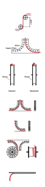
Optimal cable reel system design requires careful attention to multiple interrelated parameters. According to cable reel system manufacturers, critical design elements include drum diameter selection (insufficient diameter causes excessive bending stress and reduced flex life), groove geometry (proper groove width and depth prevents cable climbing or jumping between layers), fleet angle limitation (typically ≤4 degrees to prevent excessive side loading), and level wind mechanism design for precision cable positioning during winding.
Reel drive system must provide controlled acceleration and deceleration profiles preventing sudden tension changes that stress cable mechanically. Implement soft-start control algorithms limiting acceleration to 0.5-1.0 m/s² and providing deceleration zones before full stop. Excessive acceleration causes dynamic loading spikes potentially exceeding static tensile strength limits. Install constant-tension mechanisms (either spring-loaded systems or closed-loop tension control with load cells) maintaining optimal cable tension across entire reel travel range. Insufficient tension allows cable slack development with subsequent knotting or tangling risk, while excessive tension accelerates wear.
For multilayer cable spooling applications, implement precision level-wind systems positioning cable accurately in grooves. Layer transition points represent highest stress locations requiring careful design to minimize cable bending angle change. Provide transition ramps or tapered groove entries reducing abrupt bending. Some advanced designs incorporate automatic layer detection with programmed deceleration approaching transition points, further reducing mechanical stress.
Electrical Termination and Testing
Medium voltage cable terminations require specialized techniques and materials to maintain electrical field distribution and prevent insulation failure at high-stress cable-termination interface. Use only manufacturer-approved termination kits specifically designed for screened single-core cables at specified voltage rating. Critical termination steps include precise insulation stripping to specified dimensions (typically ±2mm tolerance), thorough cleaning of exposed insulation surface removing semiconductive residue and contamination, proper stress control cone installation ensuring complete coverage of insulation end without voids or wrinkles, and metallic screen termination to ground connection with low-resistance connection verified by measurement.
After termination completion but before energization, conduct comprehensive electrical testing validating installation quality including insulation resistance measurement (typically >1,000 MΩ for new cables at rated voltage), high-voltage DC withstand testing (2.5× U₀ for 15 minutes, monitoring leakage current for increasing trends indicative of insulation defects), and partial discharge testing (PD activity should not exceed background levels, typically <10 pC at 1.5× U₀). Document all test results with location identification for future comparative analysis during maintenance testing cycles. Implement stringent test failure protocols requiring complete termination removal and reinstallation if any test parameter fails acceptance criteria.
System Commissioning and Operational Verification
Prior to final commissioning, conduct low-speed operational testing of complete cable reel system verifying proper cable spooling, absence of mechanical interference, correct tension control functionality, and synchronization between reel drive and equipment travel. Monitor cable behavior during initial operational cycles identifying any tendency for twist development, irregular spooling patterns, or mechanical noise indicative of inadequate installation. Thermal imaging during initial loaded operation identifies hotspots at terminations or excessive friction points requiring investigation and correction before release to full operational service.
Common Failure Modes, Troubleshooting, and Preventive Maintenance
Understanding typical failure modes and their root causes enables implementation of effective preventive maintenance strategies and early intervention to prevent catastrophic failures. Statistical analysis of cable failures in mining and industrial applications reveals that approximately 70% of failures result from mechanical damage or improper installation, 20% from electrical overstress or insulation aging, and 10% from environmental degradation or chemical attack. The following sections address frequently encountered problems with diagnostic approaches and corrective strategies.
Mechanical Degradation Failure Modes
Premature Sheath Wear and Surface Damage
Symptom Identification: Visual inspection reveals surface abrasion patterns, localized thinning of outer sheath material, appearance of underlying layer (typically colored differently than sheath), cracking patterns (particularly in bend regions), or complete sheath penetration exposing internal cable components. Damage patterns often correlate with specific cable routing locations or reel system contact points.
Root Cause Analysis: Excessive mechanical abrasion results from multiple potential causes including operation below minimum bending radius specifications (generating high surface compression stresses), contact with sharp edges or burrs on reel grooves or cable support systems, contamination with abrasive particles (sand, mineral dust, metal shavings) becoming embedded in reel grooves, chemical incompatibility between sheath material and environmental contaminants, or extended exposure to UV radiation particularly affecting polyurethane materials lacking UV stabilizers. Additional factors include excessive reel speed generating high-frequency vibration and surface heating, improper cable tension allowing slapping against support structures, or multilayer spooling with inadequate groove depth causing upper cable layers to compress lower layers.
Diagnostic Testing and Assessment: Remove cable sample from damaged section for laboratory analysis including measurement of remaining sheath thickness (ultrasonic thickness gauge for non-destructive assessment), mechanical property testing (tensile strength, elongation at break, hardness) comparing results to virgin material specifications for degradation quantification, and microscopic examination of crack patterns or wear surface texture providing insight into failure mechanism. For in-service cables, thermal imaging during operation may reveal hotspots indicating localized sheath damage with increased conductor exposure.
Corrective Actions and Prevention: Immediate remediation requires isolation of damaged cable section through either localized repair (heat-shrink repair sleeve application) for minor damage or complete cable section replacement for extensive degradation. Prevention strategies include implementation of periodic visual inspection programs (monthly for severe-duty applications, quarterly for moderate service), cleaning protocols removing accumulated debris from cable surfaces and reel grooves (pressure washing or vacuum cleaning), installation of guide rollers or fairleads at high-wear locations eliminating sharp bend angles, and selection of upgraded cable specification (11Y polyurethane instead of WOEU elastomer) when analysis indicates mechanical wear exceeds design expectations. For outdoor installations with UV exposure, consider implementing protective measures such as cable covering systems or selection of UV-stabilized sheath compounds.
Conductor Strand Breakage and Fatigue Failure
Symptom Identification: Electrical symptoms include intermittent continuity (particularly during cable movement), gradually increasing conductor resistance measurable through comparison of current measurements with design values, unbalanced three-phase currents in multi-core systems, or complete open-circuit failure. Physical symptoms may include localized cable stiffness (indicating internal strand separation), audible crackling during flexing, or thermal anomalies detected through infrared scanning.
Root Cause Analysis: Conductor failure mechanisms in flexible cables primarily involve fatigue from cyclic bending stress accumulated over millions of flex cycles. Failure initiation typically occurs at locations experiencing maximum bending stress including reel transition point from drum to fixed cable section, termination entry points where cable bending combines with mechanical clamping stress, or locations where external damage introduced stress concentration points. Contributing factors include operation below minimum bending radius generating excessive strain in outer conductor strands (strain proportional to strand distance from neutral axis divided by bend radius), inadequate conductor stranding class for flex application (Class 6 flexible stranding essential for reeling applications), torsional stress in cylindrical reel applications causing additional strand loading beyond pure bending, and vibration-induced fretting between individual conductor strands accelerating wear at contact points.
Diagnostic Techniques: Time Domain Reflectometry (TDR) testing provides accurate fault location through analysis of reflected signals from impedance discontinuities caused by conductor damage. Modern TDR equipment achieves location accuracy within 0.5-1% of cable length. Insulation resistance trending monitored over time may indicate developing conductor faults through gradual decrease in measured resistance. For accessible cable sections, ultrasonic testing can detect internal strand breakage through change in acoustic transmission characteristics. Post-failure analysis should include conductor cross-section examination documenting number and location of broken strands, fracture surface analysis (optical or scanning electron microscopy) determining failure mode (fatigue, overload, or corrosion), and bend radius verification at failure location confirming installation compliance.
Corrective Actions: Conductor failure requires complete cable replacement as repair of internal conductor damage proves impractical for screened cables. Prevention strategies emphasize strict installation compliance with minimum bending radius specifications, implementation of comprehensive reel system design review verifying drum diameter adequacy (minimum 25-30D for demanding applications), evaluation of alternative reel configurations reducing torsional stress (spiral reels versus cylindrical drums), and assessment of cable specification upgrade to higher flex-life construction. For existing installations exhibiting premature failures, consider engineering analysis of actual operational stress patterns using strain gauge instrumentation to quantify loading conditions for comparison against cable design ratings.
Electrical System Failures
Insulation Degradation and Partial Discharge Activity
Symptom Identification: Early-stage insulation degradation manifests through elevated partial discharge activity detectable using ultrasonic sensors (airborne ultrasound from corona discharge) or electrical measurement techniques (HFCT sensors detecting high-frequency current pulses). Progressive degradation shows increasing leakage current measured during high-voltage testing, decreasing insulation resistance values in trend analysis, or visible corona discharge in darkened conditions. Advanced failure presents as insulation breakdown evidenced by fault current flow and protective device operation.
Root Cause Analysis: Multiple degradation mechanisms affect EPR insulation systems including moisture ingress through damaged sheath or improperly sealed terminations (moisture reduces dielectric strength by 30-50%), thermal aging from sustained operation above rated temperature accelerating chemical bond scission and cross-link degradation, mechanical damage to insulation during installation (compression, stretching, or puncture creating local weakness points), contamination of insulation-screen interface with semiconductive particles or moisture creating regions of electrical stress concentration, and electrical treeing initiated at voids or contamination sites within insulation volume. The synergistic effect of combined stressors (electrical-thermal-mechanical-environmental) produces accelerated aging exceeding predictions based on single-stress testing.
Diagnostic and Monitoring Approaches: Implement comprehensive diagnostic testing program including periodic partial discharge testing (annually for critical circuits) using either online monitoring systems for continuous surveillance or portable testing equipment for scheduled assessments. Trending of partial discharge activity (magnitude, frequency, and phase correlation) enables discrimination between different PD sources and severity assessment. Insulation resistance and polarization index testing (IR measured at 1 minute and 10 minutes after voltage application, PI = IR₁₀ₘᵢₙ / IR₁ₘᵢₙ) provides indication of moisture contamination or general insulation condition. Dissipation factor (tan δ) measurement at rated voltage quantifies dielectric losses indicative of insulation degradation. Advanced techniques including isothermal relaxation current analysis or dielectric spectroscopy provide detailed characterization of insulation condition for remaining life assessment.
Corrective Strategies: Detection of significant partial discharge activity or deteriorating insulation condition requires immediate investigation to identify root cause and implement corrective action before complete failure. For moisture-related degradation, verify termination integrity and implement enhanced sealing measures. Thermal degradation requires load reduction, improved ventilation, or cable upsizing to reduce operating temperature. Mechanical damage necessitates cable replacement or section repair if damage location can be precisely identified and isolated. Preventive strategies emphasize proper installation technique (particularly termination workmanship), implementation of condition monitoring programs enabling early detection, environmental protection (moisture barriers, temperature control, contamination prevention), and operational discipline maintaining loading within design parameters.
Emergency Response Protocols
Cable failures, particularly in medium voltage systems, present significant safety hazards including arc flash potential, fire risk, and electrical shock. Establish and maintain comprehensive emergency response procedures including immediate de-energization of faulted circuits through primary and backup protection devices, personnel evacuation from affected area maintaining safe approach distances (minimum 10 feet for medium voltage), notification of qualified electrical personnel for fault investigation, and implementation of positive isolation (visible disconnect, circuit breaker racking, fused disconnect opening) with lock-out/tag-out before personnel approach faulted equipment. Do not attempt re-energization until complete fault investigation identifies and corrects root cause.
Preventive Maintenance Program Implementation
Proactive maintenance strategies substantially extend cable system life and prevent costly unplanned outages. Implement comprehensive preventive maintenance program incorporating visual inspection (monthly for critical applications), infrared thermal scanning (quarterly during peak loading periods), partial discharge monitoring (annually or continuous for critical circuits), insulation resistance testing (annually with trending analysis), and mechanical assessment of reel systems (monthly visual examination, annual mechanical measurement of critical dimensions). Maintain detailed maintenance records documenting inspection findings, test results, corrective actions implemented, and failure history to enable trend analysis and predictive maintenance optimization. Typical maintenance costs represent 2-5% of initial cable system installation cost annually but prevent failures costing 10-50× more in emergency repairs, production losses, and equipment damage.
Engineering Selection Decision Framework
Selection between (N)TMCGCWOEU and (N)TMCGCW11Y cable specifications requires systematic evaluation of application parameters against the differentiated performance characteristics of each material technology. The following decision framework provides structured approach to cable selection optimized for specific operational requirements.
Quantitative Selection Criteria
| Selection Factor | Favor WOEU When: | Favor 11Y When: | Relative Weight |
|---|---|---|---|
| Operating Temperature | Maximum <80°C | Maximum >90°C or minimum <-30°C | High |
| Mechanical Abrasion | Moderate exposure | Severe abrasion environment | High |
| Flexibility Requirements | Bending radius >10D acceptable | Tight bending radius critical (<8D) | Medium |
| Reeling Speed | <100 m/min | >150 m/min | Medium |
| Chemical Exposure | Strong acids/alkalis present | Oil/coolant contamination | Medium |
| UV Exposure | Extensive outdoor installation | Indoor or covered installation | Medium |
| Fire Safety | Open outdoor areas | Underground/enclosed spaces | High |
| Budget Constraints | Initial cost critical | Life-cycle cost optimization | Low-Medium |
| Duty Cycle | <3,000 hours/year | >5,000 hours/year | High |
| Expected Service Life | 7-10 years acceptable | 12-15 years required | Medium |
Application-Specific Recommendations
Open-Cast Mining Equipment
Recommended: Type (N)TMCGCW11Y
Rationale: Severe mechanical stress from abrasive mineral dust, extended operational hours (6,000-8,000 hours annually), extreme temperature variations (-30°C to +50°C), and premium placed on maximizing equipment availability through extended cable life justify polyurethane specification despite higher initial cost.
Port Container Cranes
Recommended: Type (N)TMCGCW11Y
Rationale: High-speed operation (reeling speeds 150-200 m/min), intensive duty cycles (4,000-6,000 container moves annually), space constraints favoring tight bending radii, and halogen-free requirements for enclosed crane operator cabs make polyurethane optimal choice.
Bulk Material Handling – Moderate Duty
Recommended: Type (N)TMCGCWOEU
Rationale: Lower utilization rates (2,000-3,000 hours annually), moderate environmental exposure, standard flexibility adequate for typical installations, and budget sensitivity make elastomeric specification cost-effective for moderate-duty applications.
Transformer Station Connections
Recommended: Type (N)TMCGCWOEU
Rationale: Static or infrequent movement, primary requirement for electrical performance and chemical resistance, extensive outdoor exposure favoring UV-resistant elastomer, and well-proven track record in substation applications.
Life-Cycle Cost Optimization
Comprehensive economic analysis should incorporate total cost of ownership including initial procurement cost, installation labor and equipment costs, expected service life based on application duty severity, maintenance requirements and costs, downtime costs associated with cable replacement (production losses, equipment rental, labor), disposal costs at end of service life, and residual value considerations (recyclability for polyurethane). For high-utilization applications, life-cycle analysis typically demonstrates that polyurethane specifications provide 15-25% lower total cost of ownership despite 20-35% higher initial procurement costs, driven primarily by extended service life and reduced maintenance requirements. Conservative analysis should incorporate sensitivity analysis on key assumptions including failure rate estimates, downtime costs, and service life projections to ensure robust decision-making.
Industry Resources and Technical References
- Comprehensive Technical Library: Reeling Cables for Port and Mining Machinery Systems
- Australian Mining Cable Applications: Installation Guidelines and Product Specifications
- Crane Cable and Festoon Systems Engineering: Design Standards and Best Practices
- Soluciones Técnicas de Cables Mineros para América Latina
- 飛純電纜繁體中文技術文獻資料庫
Conclusion: Evidence-Based Cable Selection
The fundamental distinction between (N)TMCGCWOEU and (N)TMCGCW11Y cable specifications resides in the material science and engineering properties of their respective sheath materials. Thermoset elastomeric construction (WOEU) provides exceptional chemical resistance, superior UV stability, proven reliability, and competitive cost structure suitable for standard to moderate-duty applications. Thermoplastic polyurethane construction (11Y) delivers enhanced mechanical flexibility, superior abrasion resistance, extended thermal operating range, halogen-free safety characteristics, and exceptional flex life justifying premium pricing for demanding high-performance applications.
Both cable types conform to rigorous DIN VDE 0250-813 specifications ensuring fundamental safety and reliability. Selection between variants should be driven by systematic evaluation of application-specific requirements including environmental conditions, mechanical loading patterns, duty cycle intensity, safety requirements, and economic optimization considering total cost of ownership rather than initial procurement cost alone. The quantitative performance data, comparative analysis, and selection framework presented in this technical evaluation enable informed engineering decisions aligned with specific operational requirements and organizational objectives.
Feichun’s commitment to manufacturing excellence, materials innovation, and customer support ensures that regardless of specification selected, you receive cable solutions engineered for reliable performance in the world’s most demanding mining and industrial applications. Our technical team remains available to provide application-specific guidance, custom engineering solutions, and ongoing support throughout your equipment operational lifecycle.


