
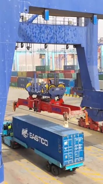
24G2.5 Crane Reeling Cable Specification Guide: 24×2.5 mm² Multi-Core Control Cable for STS, RTG & RMG Cranes — NSHTÖU-J / PUR, VDE 0250-814 / 0250-818, Anti-Torsion Braid, Stranding Pitch Engineering, and FeiChun Drop-In Equivalent
A definitive engineering specification guide for port electrical engineers, crane automation integrators, and terminal procurement teams who need to specify, source, or replace the 24G2.5 (24×2.5 mm²) multi-core control reeling cable — the critical signal backbone of modern container crane automation systems. This document covers every layer of the cable’s construction from the inside out: Class 5 and Class 6 tinned copper stranding options per IEC 60228, the precisely optimised stranding pitch (lay length) that equalises tensile stress across all 24 cores during dynamic bending, 3GI3 EPR versus TPE insulation selection criteria for signal integrity under continuous flexing, the vulcanised anti-torsion braid that prevents the catastrophic “corkscrewing” failure mode unique to high-core-count reeling cables, and the outer sheath decision between 5GM5 polychloroprene (neoprene) for maximum ozone/UV/saltwater resistance and polyurethane (PUR) for extreme mechanical abrasion environments. VDE compliance is mapped to both DIN VDE 0250-814 (rubber-sheathed reeling cables) and DIN VDE 0250-818 (PUR-sheathed reeling cables). Core identification follows IEC 60227 conventions: 23 black cores with white printed numbers plus one green/yellow earth core. Typical applications include PLC I/O signal transmission, twist-lock sensor feedback, limit switch circuits, anti-collision radar interfaces, load-cell data, and 24 VDC auxiliary power distribution on STS (Ship-to-Shore), RTG (Rubber-Tyred Gantry), RMG (Rail-Mounted Gantry), and heavy industrial overhead cranes.
繁體中文摘要:本文為港口電氣工程師、起重機自動化整合商及碼頭採購團隊編寫的權威工程規格指南,針對 24G2.5(24×2.5 mm²)多芯控制卷纜——現代集裝箱起重機自動化系統的關鍵信號骨幹。內容涵蓋電纜從內到外的每一層結構:IEC 60228 第 5 類和第 6 類鍍錫銅絞線選項、精確優化的絞纜節距(纜距)以在動態彎曲時均衡全部 24 芯的拉伸應力、3GI3 EPR 與 TPE 絕緣在持續彎曲下信號完整性的選擇準則、防止高芯數卷纜獨有之「螺旋變形」失效模式的硫化抗扭轉編織層,以及 5GM5 氯丁橡膠(耐臭氧/紫外線/海水)與聚氨酯(PUR,極端機械磨損環境)外護套的選擇決策。標準合規對應 DIN VDE 0250-814(橡膠護套卷纜)和 DIN VDE 0250-818(PUR 護套卷纜)。典型應用包括 PLC I/O 信號傳輸、旋鎖感測器回饋、限位開關電路、防碰撞雷達介面、荷重元數據及 24 VDC 輔助電源配電。
1. Why the 24G2.5 Is the Most Failure-Critical Cable on a Modern Container Crane
A modern STS or RTG crane carries two categories of reeling cable: the power cable (typically 3–4 cores at 50–150 mm²) that delivers megawatts of main drive power, and the control cable (typically 12–36 cores at 1.5–4.0 mm²) that transmits every sensor reading, limit switch state, and PLC command that governs the crane’s automated operation. When the power cable fails, the crane stops — but the failure mode is obvious (loss of supply, trip on overcurrent) and the crane halts safely. When the control cable fails, the consequences are far more insidious: intermittent signal dropouts cause erratic spreader behaviour, phantom twist-lock alarms, false anti-collision triggers, and diagnostic error codes that send maintenance teams on hours-long troubleshooting exercises — all while the crane continues to operate in a degraded, potentially unsafe mode.
繁體中文:當動力電纜失效時,起重機停止運行——但失效模式顯而易見。當控制電纜失效時,後果遠更隱蔽:間歇性信號中斷導致吊具行為異常、旋鎖虛假報警、防碰撞誤觸發和診斷錯誤代碼,迫使維護團隊花費數小時排查問題——而起重機在此期間持續以降級且可能不安全的模式運行。
The 24G2.5 configuration — 24 cores of 2.5 mm² each — has emerged as the industry-standard multi-core control reeling specification because it provides sufficient core count for a complete crane control system (typically requiring 18–22 active signal/power circuits plus 1–2 spare cores for future expansion) with a conductor cross-section (2.5 mm²) that balances current-carrying capacity for mixed signal and 24 VDC auxiliary loads (rated at approximately 25 A per core in free air per IEC 60364-5-52 Table B.52.4) against the cable’s overall outer diameter and weight, which must remain within the mechanical limits of the crane’s control cable reel.
繁體中文:24G2.5 配置——24 芯各 2.5 mm²——已成為行業標準的多芯控制卷纜規格,因為它為完整的起重機控制系統提供了足夠的芯數(通常需要 18–22 條有效信號/電源回路加 1–2 條備用芯線),且導體截面(2.5 mm²)在載流能力與電纜整體外徑和重量之間取得平衡。
The engineering challenge is that a 24-core cable is intrinsically far more susceptible to internal mechanical failure under reeling duty than a 3- or 4-core power cable. With 24 individual cores arranged in concentric layers around a central filler, the cores in the outermost layer travel a measurably longer path around each bend than the cores at the cable centre. Over thousands of reeling cycles, this differential path length creates differential tensile stress — and if the cable’s stranding pitch (lay length) and anti-torsion braid are not precisely engineered for this specific core count, the result is progressive core migration, twisting, bunching, and ultimately the fracture of individual copper conductors that manifests as the intermittent signal failures described above. This guide provides the engineering detail required to specify, procure, and install a 24G2.5 reeling cable that will survive its full rated service life of 20,000–50,000 cycles without a single core failure.
2. Full Technical Specification: 24G2.5 NSHTÖU-J and PUR Variants
The 24G2.5 reeling cable is available in two outer-sheath variants — the NSHTÖU-J (neoprene-sheathed, per DIN VDE 0250-814) and the PUR-reeling variant (polyurethane-sheathed, per DIN VDE 0250-818). Both variants share identical internal construction (conductors, insulation, stranding, anti-torsion braid, inner sheath) and differ only in the outer sheath compound. The following table provides the complete specification.
繁體中文:24G2.5 卷纜有兩種外護套型號——NSHTÖU-J(氯丁橡膠護套,依據 DIN VDE 0250-814)和 PUR 卷纜型號(聚氨酯護套,依據 DIN VDE 0250-818)。兩種型號內部結構完全相同,僅外護套化合物不同。
| Parameter | NSHTÖU-J 24G2.5 (Neoprene) | PUR 24G2.5 (Polyurethane) | Governing Standard |
|---|---|---|---|
| VDE Standard | DIN VDE 0250-814 | DIN VDE 0250-818 | VDE 0250 series |
| Core Configuration | 24G2.5 mm² (23 black + 1 green/yellow PE) | VDE 0293 / IEC 60227 | |
| Rated Voltage (U₀/U) | 0.6/1 kV | VDE 0250-814 / -818 | |
| Conductor Material | Tinned electrolytic copper, Class 5 (standard) or Class 6 (premium) | IEC 60228 | |
| Max. Wire Diameter | ≤ 0.16 mm (Class 5) / ≤ 0.10 mm (Class 6) | IEC 60228 Table 4 | |
| Conductor Resistance (20°C) | ≤ 7.98 Ω/km (Class 5) / ≤ 8.21 Ω/km (Class 6) | IEC 60228 | |
| Insulation Compound | EPR, Type 3GI3 (peroxide-cured) | TPE or EPR, Type 3GI3 | VDE material tables |
| Insulation Wall Thickness | ≥ 0.8 mm (2.5 mm² per VDE 0250-814 Table 3) | VDE 0250-814 | |
| Core Identification | 23 black cores, white inkjet numbered 1–23; 1 green/yellow PE | VDE 0293-308 / IEC 60227 | |
| Stranding Lay Type | Concentric SZ-stranding, optimised lay length 12–16× cable OD | Manufacturer spec (VDE-enhanced) | |
| Anti-Torsion Braid | High-tensile polyester or Kevlar, vulcanised between inner and outer sheaths | Manufacturer spec | |
| Inner Sheath | Neoprene (CR), 5GM5 | TPU inner compound | VDE material tables |
| Outer Sheath | Polychloroprene (CR), 5GM5, black or custom RAL | Polyurethane (PUR), high-abrasion grade | VDE 0250-814 / -818 |
| Outer Diameter (approx.) | ~32–38 mm | ~30–36 mm | Manufacturer datasheet |
| Cable Weight (approx.) | ~2.2–2.8 kg/m | ~2.0–2.5 kg/m | Manufacturer datasheet |
| Max. Dynamic Tensile Stress | 15 N/mm² × total copper cross-section = 15 × (24 × 2.5) = 900 N max | VDE 0250-814 Annex A | |
| Travel Speed | Up to 120 m/min | Up to 180 m/min | Manufacturer validation |
| Temperature Range (dynamic) | -25°C to +80°C | -30°C to +80°C | VDE 0250-814 / -818 |
| Min. Bending Radius (dynamic) | 7.5 × OD | VDE 0250-814 | |
| Flex Life (rated cycles) | 20,000–50,000 full-travel cycles | 30,000–80,000 full-travel cycles | VDE 0250-814 / -818 Cl. 6.4 |
3. Differential Core Travel: The Physics Behind Multi-Core Reeling Failure
The single most important concept to understand about multi-core reeling cables is differential core travel — the geometric fact that when a multi-layer assembly of cylindrical cores is bent around a drum, cores on the outside of the bend travel a longer path than cores on the inside. In a 3-core power cable (where all cores are in a single concentric layer), this effect is minimal because the path-length difference between any two cores is small relative to each core’s absolute length. In a 24-core cable, where the cores are arranged in at least three concentric layers (typically 1 central filler + 6 cores in layer 1 + 12 cores in layer 2 + 6 cores in layer 3, or similar arrangements), the outermost core travels measurably farther than the innermost core at every bend.
繁體中文:理解多芯卷纜的最核心概念是差異性芯線行程——當多層圓柱形芯線組件繞卷筒彎曲時,彎曲外側的芯線比內側的芯線走過更長的路徑。在 3 芯動力電纜中,此效應微小;而在 24 芯電纜中,芯線至少排列成三個同心層,最外層芯線在每次彎曲時行程顯著長於最內層芯線。
The mathematics are straightforward. Consider a cable with outer diameter D = 35 mm, wound around a drum with core diameter d_drum = 350 mm (which satisfies the 7.5× OD minimum: 7.5 × 35 = 262.5 mm). The radius of curvature at the cable centre is R_c = (d_drum + D) / 2 = 192.5 mm. A core positioned at the outermost layer (approximately 12 mm from the cable centre) bends at radius R_outer = 192.5 + 12 = 204.5 mm, while a core at the innermost layer (approximately 5 mm from centre) bends at R_inner = 192.5 – 5 = 187.5 mm. For a single 180° bend (half a drum revolution), the outer core travels π × 204.5 = 642.5 mm while the inner core travels π × 187.5 = 589.0 mm — a difference of 53.5 mm per half-revolution. Over a 200-metre cable payout that involves approximately 180 drum revolutions (on a 350 mm drum), the cumulative differential travel is approximately 180 × 2 × 53.5 = 19,260 mm — nearly 20 metres of relative slippage between the outermost and innermost cores.
For 24G2.5: ΔL ≈ 2π × (12 − 5) = 2π × 7 ≈ 44 mm per revolution
繁體中文:計算表明:在 200 米電纜放出過程中涉及約 180 圈卷筒旋轉,最外層和最內層芯線之間的累計差異行程約為 19,260 mm——接近 20 米的相對滑移。如果電纜設計不能容納此差異行程,芯線將扭曲、堆積並最終斷裂。
If the cable’s construction cannot accommodate this differential travel, the outer cores are placed under progressively increasing tensile stress (because they are being forced to travel farther while being physically constrained within the cable assembly), while the inner cores experience compressive buckling. Over thousands of cycles, this stress accumulation causes the cores to migrate from their designed positions within the cable cross-section — a process known as “core migration” or “bird-caging.” Once migration begins, it becomes self-reinforcing: a displaced core occupies space intended for an adjacent core, which is then also displaced, creating a cascade of positional errors that ultimately leads to the visible “corkscrew” deformation of the entire cable assembly. The stranding pitch and anti-torsion braid — detailed in Sections 4 and 7 — are the two engineering solutions to this problem.
4. Stranding Pitch Engineering: Optimising Lay Length for Equal-Tension Reeling
The stranding pitch — also called the lay length — is the axial distance required for one complete helical revolution of a core around the cable’s central axis. In a 24G2.5 reeling cable, the lay length is the single most important manufacturing parameter because it directly controls how differential core travel is distributed along the cable’s length. An incorrectly set lay length is the root cause of the majority of multi-core reeling cable failures, and it is the parameter most commonly compromised by non-specialised manufacturers attempting to produce reeling cables on general-purpose stranding equipment.
繁體中文:絞纜節距(纜距)——即一根芯線繞電纜中心軸完成一圈螺旋所需的軸向距離——是 24G2.5 卷纜中最重要的製造參數,因為它直接控制差異性芯線行程如何沿電纜長度分配。設定不正確的纜距是多芯卷纜失效的主要根本原因。
The physics of lay-length optimisation is rooted in a concept from classical mechanics: when a helically wound element is bent around a radius, the helix acts as a spring that allows each element to accommodate differential path lengths by slightly elongating or compressing along its helical path without being placed under excessive axial tension. The optimal lay length creates a helix angle at which the differential travel per drum revolution is exactly absorbed by the helical “spring effect” — meaning the outer cores extend slightly along their helix and the inner cores compress slightly, with no net change in axial tension on any individual core. Per the helical spring mechanics described in Feyrer’s “Wire Ropes” (Springer, 2007) and adapted for multi-core cable geometry, the optimal lay length for a reeling cable is typically 12–16× the cable outer diameter, with the exact value depending on the number of core layers, the layer radii, and the drum diameter.
繁體中文:纜距優化的物理學根植於經典力學概念:當螺旋纏繞的元件繞半徑彎曲時,螺旋結構像彈簧一樣允許每個元件通過沿其螺旋路徑略微伸長或壓縮來適應差異性路徑長度,而不承受過大的軸向張力。最佳纜距通常為電纜外徑的 12–16 倍。
For a 24G2.5 cable with an OD of approximately 35 mm, the optimal lay-length window is 420–560 mm (12× to 16× OD). Within this window, the exact value is fine-tuned based on the stranding configuration. FeiChun uses a concentric SZ-stranding pattern (also known as reversing-lay stranding), where each concentric layer is wound in the opposite rotational direction to the layer below it, and the lay direction reverses at regular intervals along the cable length. This SZ pattern provides two critical advantages over unidirectional stranding. First, it eliminates the residual torsional moment that would otherwise cause the cable to twist when tensioned — because the clockwise torque from one layer is balanced by the counter-clockwise torque from the adjacent layer. Second, the reversing points act as strain-relief anchors that prevent cumulative differential-travel stress from propagating over long cable lengths; instead, the stress is distributed in short segments between each reversal point.
FeiChun’s 24G2.5 cables are manufactured on a planetary-cage stranding line with individually servo-controlled bobbin stations, allowing real-time adjustment of lay length to within ±2 mm precision. The lay-length tolerance for every production reel is verified by measuring the helix pitch at 5 randomly selected points along the cable using a laser-triangulation sensor, with all measurements documented in the cable’s quality certificate. 飛純的 24G2.5 電纜在行星籠式絞纜生產線上製造,配備各自伺服控制的線軸站,允許即時調整纜距至 ±2 mm 精度範圍內。
5. Conductor Selection: Class 5 vs. Class 6 Stranding for 2.5 mm² Cores
IEC 60228 defines two flexibility classes that are relevant for reeling cable conductors: Class 5 (flexible) and Class 6 (extra-flexible, for cables requiring increased flexibility). For the 2.5 mm² conductor size used in the 24G2.5 configuration, the practical differences between these two classes have significant implications for both flex life and cost.
繁體中文:IEC 60228 定義了兩個與卷纜導體相關的撓性等級:第 5 類(撓性)和第 6 類(超撓性,用於需要更高撓性的電纜)。對於 24G2.5 配置中使用的 2.5 mm² 導體,這兩個等級之間的實際差異對彎曲壽命和成本都有重要影響。
| Parameter | Class 5 | Class 6 | Implication for 24G2.5 |
|---|---|---|---|
| Max. wire diameter | 0.16 mm | 0.10 mm | Class 6 wires are 37.5% thinner |
| Min. wire count (2.5 mm²) | ~127 wires | ~320 wires | Class 6 has 2.5× more wires per core |
| Max. DC resistance (20°C) | 7.98 Ω/km | 8.21 Ω/km | Class 6 slightly higher (more air gaps) |
| Min. bending radius (dynamic) | 7.5 × OD | 6.0 × OD | Class 6 allows tighter drum radius |
| Rated flex cycles (typical) | 20,000–50,000 | 40,000–100,000 | Class 6 doubles the flex life |
| Cost premium | Baseline | +15–25% | Higher wire count = more processing |
The fundamental principle is that thinner wires bend with lower strain at the wire surface. The bending strain in a solid circular wire is given by ε = d_wire / (2 × R_bend), where d_wire is the wire diameter and R_bend is the bending radius. For a Class 5 wire (0.16 mm) bending at 7.5× OD on a 35 mm cable (R_bend ≈ 131 mm): ε = 0.16 / (2 × 131) = 0.061% — well below the copper fatigue limit of approximately 0.2% per Copper Development Association fatigue data. For a Class 6 wire (0.10 mm) at the same radius: ε = 0.10 / (2 × 131) = 0.038% — approximately 38% lower strain, which translates to a dramatically longer fatigue life per Coffin-Manson low-cycle fatigue theory.
繁體中文:基本原理是更細的銅絲在彎曲時表面應變更低。第 5 類銅絲(0.16 mm)的彎曲應變為 0.061%,而第 6 類銅絲(0.10 mm)的彎曲應變為 0.038%——低約 38%,這根據 Coffin-Manson 低循環疲勞理論轉化為顯著更長的疲勞壽命。
FeiChun offers the 24G2.5 in both Class 5 (standard) and Class 6 (premium) stranding. The recommendation depends on the duty cycle: for RTG cranes operating at moderate travel speeds (≤80 m/min) with fewer than 20,000 full-travel cycles over the cable’s planned service life, Class 5 provides an optimal balance of performance and cost. For STS cranes or high-utilisation RTGs operating at 120+ m/min with a target of 40,000+ cycles, Class 6 is the correct specification — the 15–25% cost premium is trivially justified by the 2× improvement in flex life, which effectively halves the annualised cable replacement cost.
6. Insulation: 3GI3 EPR vs. TPE for Signal Integrity Under Cyclic Flexing
The insulation compound in a multi-core control reeling cable serves a dual function that is not present in power reeling cables: it must provide both electrical isolation between cores (the standard function) and sufficient dielectric consistency to maintain signal integrity for PLC-level digital and analogue signals under the continuous mechanical deformation of reeling duty. Two compound families are used in the 24G2.5 specification: 3GI3 EPR (the same peroxide-cured ethylene-propylene rubber used in power reeling cables) and TPE (thermoplastic elastomer, typically an SEBS-based compound).
繁體中文:多芯控制卷纜中的絕緣化合物承擔雙重功能:既要提供芯線間的電氣隔離,又要保持足夠的介電一致性以維護 PLC 級數位和類比信號在持續機械變形下的信號完整性。24G2.5 規格使用兩種化合物系列:3GI3 EPR 和 TPE(熱塑性彈性體)。
| Parameter | 3GI3 EPR | TPE (SEBS-based) | Significance for Signal Integrity |
|---|---|---|---|
| Dielectric constant (εr) | 2.8–3.2 | 2.3–2.6 | Lower εr = lower mutual capacitance = less crosstalk |
| Mutual capacitance (typical) | ~120–150 nF/km (core-to-core) | ~80–110 nF/km (core-to-core) | TPE superior for signal-dense applications |
| Insulation resistance (MΩ·km) | ≥ 100 | ≥ 200 | TPE provides higher IR margin |
| Temperature range | -25°C to +90°C | -30°C to +80°C | EPR superior at high temps; TPE superior at low temps |
| Oil resistance | Good (3GI3 highest EPR grade) | Moderate | EPR preferred for oily environments (engine rooms) |
| Flex-life impact | Baseline | +10–20% improvement | TPE softer (Shore A 60–70 vs. 65–75), less micro-cracking |
| Fire behaviour | Self-extinguishing per IEC 60332-1 | Self-extinguishing per IEC 60332-1 | Both acceptable for port crane use |
For applications where the 24G2.5 cable carries a mix of 24 VDC power circuits and high-speed PLC digital signals (e.g., PROFINET or EtherNet/IP over dedicated core pairs), the lower mutual capacitance of TPE insulation provides a measurable advantage in signal integrity — particularly over cable lengths exceeding 100 metres, where core-to-core capacitance begins to attenuate high-frequency signal edges. For applications where the cable operates in hot, oily environments (e.g., near crane drive machinery) or where the temperature routinely exceeds 70°C, 3GI3 EPR is the correct choice because of its superior thermal stability and oil resistance. FeiChun manufactures the 24G2.5 in both insulation options and can advise on the optimal selection based on the specific crane control architecture and signal types. Contact [email protected] with your control system schematic for a recommendation.
7. The Anti-Torsion Braid in Multi-Core Cables: Why 24 Cores Need It More Than 4
The anti-torsion braid — a woven layer of high-tensile synthetic fibres (Kevlar or high-tenacity polyester) vulcanised between the inner and outer sheaths — is important in every reeling cable, but it is absolutely indispensable in multi-core configurations like the 24G2.5. The reason relates directly to the differential core travel discussed in Section 3: when 24 cores are subjected to differential tensile stress, the resulting internal forces do not merely cause the individual cores to shift position — they generate a net torsional moment on the cable assembly as a whole, because the outer-layer cores (which are under greater tension) create an asymmetric force distribution that attempts to rotate the cable around its longitudinal axis.
繁體中文:抗扭轉編織層在每種卷纜中都很重要,但在 24G2.5 等多芯配置中絕對不可或缺。原因直接與第 3 節討論的差異性芯線行程有關:當 24 根芯線受到差異性拉伸應力時,產生的內力不僅導致個別芯線移位——它們在電纜組件整體上產生淨扭轉力矩。
In a 4-core power cable, the torsional moment generated by differential core travel is relatively small because there is only one layer of cores, all at approximately the same radial distance from the cable centre. The moment arm is minimal, and the cable’s inherent torsional stiffness (provided by the rubber matrix alone) is usually sufficient to resist it. In a 24-core cable with three concentric core layers, the torsional moment is approximately proportional to the number of cores in the outermost layer multiplied by the radial distance of that layer from the cable centre — a product that is roughly 3–5× greater than in a 4-core cable. Without a dedicated torsion-resistant structure (the braid), this moment will rotate the cable during each reeling cycle, progressively winding torsional strain into the cable. After 500–2,000 cycles (depending on the drum tension), the accumulated torsional strain exceeds the limit, and the cable corkscrews.
FeiChun’s anti-torsion braid for the 24G2.5 uses the same vulcanised-braid technology as its power reeling cables: a high-tenacity polyester braid (tensile strength ~1,100 MPa) or Kevlar/Twaron braid (tensile strength ~3,600 MPa) woven at 54.7° neutral braid angle per the principles described in Composites Science and Technology, Vol. 67, 2007. The braid is applied onto the freshly extruded (uncured) inner sheath, and the outer sheath is immediately extruded over it, so that the vulcanisation process chemically bonds the braid fibres to both rubber surfaces. This creates a torsionally rigid but longitudinally flexible cylindrical cage that locks the 24-core assembly in position while still allowing the cable to flex freely around the drum radius.
Many generic “24G2.5 flexible cable” products available on the market do not include an anti-torsion braid. These cables are designed for festoon or cable-chain applications where the cable hangs in a catenary and is not subjected to drum winding forces. Installing a non-braided cable on a motorised reeling drum will result in corkscrewing within 2–8 weeks, causing intermittent control signal failures that are extremely difficult to diagnose. Always verify the presence of a vulcanised anti-torsion braid before accepting any 24G2.5 cable for reeling duty. 市場上許多通用「24G2.5 軟電纜」不含抗扭轉編織層。將無編織層電纜安裝在電動卷纜器上將在 2–8 週內導致螺旋變形。務必在接受任何用於卷纜的 24G2.5 電纜之前驗證是否存在硫化抗扭轉編織層。
8. Outer Sheath Decision: 5GM5 Neoprene vs. Polyurethane (PUR)
The outer sheath is the cable’s first and only line of defence against the external environment, and the choice between 5GM5 neoprene (polychloroprene, CR) and polyurethane (PUR) is not interchangeable — it must be matched to the specific environmental and mechanical conditions at the cable’s installation site.
繁體中文:外護套是電纜抵禦外部環境的第一道也是唯一的防線,5GM5 氯丁橡膠和聚氨酯(PUR)之間的選擇不可互換——必須與電纜安裝地點的具體環境和機械條件匹配。
| Environmental / Mechanical Factor | 5GM5 Neoprene (CR) | PUR | Recommendation |
|---|---|---|---|
| Saltwater / marine atmosphere | Excellent (inherent hydrophobicity) | Good (requires UV-stabilised grade) | Neoprene for coastal ports |
| Ozone resistance (coastal UV + corona) | Excellent (zero cracking at 50 ppm / 100 h) | Good | Neoprene for outdoor tropical/subtropical |
| UV radiation resistance | Excellent (carbon black + CR chemistry) | Moderate (requires additive package) | Neoprene for unshielded outdoor runs |
| Abrasion resistance (metal grating, guide rollers) | Good (DIN loss ~120 mm³) | Excellent (DIN loss ~40–60 mm³) | PUR for heavy metal-contact abrasion |
| Cut and tear resistance | Good | Excellent (2–3× neoprene) | PUR for sharp-edge environments |
| Oil and hydrocarbon resistance | Good (5GM5 highest CR grade) | Moderate (some PUR grades swell) | Neoprene for oily environments |
| Flame retardancy | Inherent (chlorine content ~35%) | Requires additive package | Neoprene for fire-rated requirements |
| Low-temperature flexibility | -25°C (typical minimum) | -30°C to -40°C (depending on grade) | PUR for cold-climate ports |
| Travel speed capability | Up to 120 m/min | Up to 180 m/min | PUR for high-speed modern cranes |
| Cable weight | ~2.2–2.8 kg/m | ~2.0–2.5 kg/m (5–15% lighter) | PUR for weight-sensitive drum capacities |
In practice, the decision follows a simple rule: if the crane operates in a coastal port with significant saltwater, UV, and ozone exposure, and the control cable reel speed is ≤ 120 m/min, specify the NSHTÖU-J (neoprene) variant. If the crane operates in an inland terminal, a covered facility, or any environment where metal-to-cable abrasion is the dominant wear mechanism, and/or the reel speed exceeds 120 m/min, specify the PUR variant. FeiChun manufactures both variants with identical internal construction, so the decision affects only the outer sheath — the signal performance, flex life (at a given conductor class), and anti-torsion properties are identical between the two.
9. Core Identification and Numbering per IEC 60227 / VDE 0293
Correct core identification is critical for a 24-core control cable because any wiring error during termination can cause a control signal to be connected to the wrong PLC input — a fault that may not be detected during commissioning and can cause dangerous crane behaviour during operation. The 24G2.5 follows the core identification conventions of IEC 60227 and VDE 0293-308: 23 cores with black insulation, each individually numbered with white inkjet printing (numbers 1 through 23), plus one green/yellow earth core (PE). The “G” in “24G2.5” denotes the presence of this protective earth core (Grün-gelb in German).
繁體中文:正確的芯線標識對 24 芯控制電纜至關重要,因為接線端子處的任何接線錯誤都可能將控制信號連接到錯誤的 PLC 輸入。24G2.5 遵循 IEC 60227 和 VDE 0293-308 的芯線標識規範:23 根黑色絕緣芯線,每根以白色噴碼標記編號 1 至 23,加一根綠/黃接地芯線(PE)。
The inkjet numbering must satisfy two requirements under VDE 0293-308: legibility and durability. Legibility means the numbers must be printed at a minimum height of 2.5 mm with a repeat interval of no more than 50 mm along the core length, ensuring that the technician can identify any core at any point along the cable without stripping more than 50 mm of outer sheath. Durability means the printing must survive the mechanical abrasion and chemical exposure of the cable’s service environment — the numbers must remain legible after 10,000 flex cycles (per the VDE 0250-814 type test) and after immersion in common industrial solvents (IPA, mineral oil) for 24 hours. FeiChun uses a UV-cured inkjet system that bonds the pigment directly to the EPR or TPE insulation surface, achieving adhesion values exceeding 3 N/mm in the peel test per ISO 2409 cross-cut method — significantly exceeding the minimum VDE requirement.
10. Signal Integrity: Capacitance, Crosstalk, and EMI in Dynamic Reeling
A 24G2.5 control cable carrying a mix of PLC digital signals (24 VDC), analogue sensor inputs (4–20 mA or 0–10 V), and auxiliary power circuits (24 VDC at up to 10 A) must maintain signal integrity under conditions that would compromise most static installation cables: continuous mechanical vibration, periodic compression during multi-layer winding, and electromagnetic interference (EMI) from the adjacent power reeling cable and the crane’s variable-frequency drive (VFD) systems.
繁體中文:承載 PLC 數位信號(24 VDC)、類比感測器輸入(4–20 mA 或 0–10 V)和輔助電源回路的 24G2.5 控制電纜,必須在持續機械振動、多層纏繞時的週期性壓縮,以及來自相鄰動力卷纜和起重機變頻驅動系統的電磁干擾條件下維持信號完整性。
Mutual capacitance — the capacitance between any two cores within the cable — is the primary parameter governing crosstalk in multi-core control cables. When a 24 VDC digital signal transitions from 0 V to 24 V on one core, the rate of voltage change (dV/dt) couples through the mutual capacitance to adjacent cores, inducing a transient voltage pulse. If this induced pulse exceeds the noise margin of the receiving PLC input (typically ±5 V for a 24 VDC input per IEC 61131-2), it can be misinterpreted as a signal transition — causing a phantom sensor reading or a false limit-switch trigger. The induced voltage is proportional to the mutual capacitance and the dV/dt of the aggressor signal: V_induced = C_mutual × dV/dt × Z_victim, where Z_victim is the impedance seen by the victim core.
For a 200-metre cable with 3GI3 EPR insulation (C_mutual ≈ 130 nF/km, so 200 m = 26 nF) and a typical 24 VDC transition time of 1 ms: V_induced = 26 × 10⁻⁹ × (24 / 0.001) × 1000 ≈ 0.62 V — comfortably below the ±5 V noise margin. However, for faster signal edges (e.g., PROFINET with transition times of ~10 ns) or longer cable runs, the induced voltage can approach or exceed the noise margin, requiring either TPE insulation (with its 20–30% lower capacitance) or the use of dedicated shielded pairs within the cable assembly. FeiChun offers a premium variant of the 24G2.5 with individually shielded pair groups (e.g., 4 shielded pairs + 16 unshielded cores) for terminals using PROFINET or EtherNet/IP crane control architectures.
11. Slip-Clutch Tension Calculation for 24G2.5 Configurations
The slip-clutch tension limit for the 24G2.5 is significantly lower than for power reeling cables, because the total copper cross-section is smaller — and exceeding this limit on a multi-core cable causes a failure mode (individual core fracture) that is far more difficult to diagnose than the obvious sheath damage caused by over-tensioning a power cable.
繁體中文:24G2.5 的滑動離合器張力限值顯著低於動力卷纜,因為總銅截面積更小——且在多芯電纜上超過此限值所導致的失效模式(單根芯線斷裂)比動力電纜過度張力造成的明顯護套損傷更難診斷。
F_max = 15 N/mm² × 60 mm² = 900 N (≈ 91.7 kg)
Recommended slip-clutch setting (80%): 720 N (≈ 73.4 kg)
This is an extremely low tension value — less than one-quarter of the typical setting for a 4×50 mm² power cable on the same crane. The slip-clutch on the control cable reel must be set independently of the power cable reel, and it must be verified with a calibrated load cell during commissioning. A common error is to set the control cable reel’s slip-clutch to the same value as the power cable reel — this will apply approximately 4× the safe tension to the 24G2.5 cable, causing immediate plastic deformation of the copper conductors and progressive core fracture over the following weeks.
繁體中文:這是一個極低的張力值——不到同一起重機上典型 4×50 mm² 動力電纜設定值的四分之一。控制電纜卷筒的滑動離合器必須獨立於動力電纜卷筒單獨設定。一個常見錯誤是將控制電纜卷筒的離合器設定為與動力電纜卷筒相同的值——這將對 24G2.5 電纜施加約 4 倍的安全張力。
Cable weight also matters for the 24G2.5. At approximately 2.5 kg/m (neoprene variant), a 150-metre payout creates a suspended cable weight of approximately 375 kg (3,679 N) — which exceeds the 900 N conductor tensile limit by more than 4×. This means that every 24G2.5 control cable reel installation must use a gravity-assisted drum configuration, a dancer-arm tensioner, or a cable-track support system that prevents the cable’s own weight from loading the conductors. This is a fundamentally different engineering constraint than for power cables (where the conductor cross-section is large enough to safely support the cable weight), and it must be explicitly addressed in the crane’s cable management system design.
FeiChun provides complimentary cable-management system analysis for 24G2.5 control reeling installations, including drum configuration (gravity-assisted vs. dancer-arm), tension profile modelling, and guide-roller spacing calculations. Submit your crane model and control cable routing to [email protected]. 飛純為 24G2.5 控制卷纜安裝提供免費的電纜管理系統分析,包括卷筒配置、張力曲線建模和導輪間距計算。
12. FeiChun NSHTÖU-J 24G2.5: Construction Parity and Drop-In Validation
FeiChun manufactures the NSHTÖU-J 24G2.5 and PUR 24G2.5 control reeling cables as validated drop-in equivalents to the corresponding products from Prysmian (PROTOMONT 24G2.5), TF Kable (TFCrane Control), Lapp (ÖLFLEX CRANE 24G2.5), and Nexans (RHEYFIRM 24G2.5). “Drop-in equivalent” means the FeiChun cable can be installed on the same crane drum, with the same guide rollers, cable glands, and terminal blocks, without any mechanical modification.
繁體中文:飛純製造的 NSHTÖU-J 24G2.5 和 PUR 24G2.5 控制卷纜,是 Prysmian(PROTOMONT 24G2.5)、TF Kable(TFCrane Control)、Lapp(ÖLFLEX CRANE 24G2.5)和 Nexans(RHEYFIRM 24G2.5)對應產品的經驗證直接替換品。
| European Brand Product | VDE Designation | FeiChun Equivalent | OD Tolerance | Validated Applications |
|---|---|---|---|---|
| Prysmian PROTOMONT 24G2.5 | NSHTÖU-J 0.6/1 kV | FeiChun NSHTÖU-J 24G2.5 | ±1.5% OD | STS, RTG, RMG (ZPMC, Liebherr, Konecranes) |
| TF Kable TFCrane Control 24G2.5 | NSHTÖU-J 0.6/1 kV | FeiChun NSHTÖU-J 24G2.5 | ±1.8% OD | STS, RTG (ZPMC, Kalmar) |
| Lapp ÖLFLEX CRANE 24G2.5 | NSHTÖU-J 0.6/1 kV | FeiChun NSHTÖU-J 24G2.5 | ±1.5% OD | Overhead process cranes, RMG |
| Nexans RHEYFIRM 24G2.5 | NSHTÖU-J 0.6/1 kV | FeiChun NSHTÖU-J 24G2.5 | ±2.0% OD | STS, ship unloader, stacker reclaimer |
| Any European PUR 24G2.5 | VDE 0250-818 | FeiChun PUR 24G2.5 | ±1.5% OD | High-speed RTG, ASC, indoor overhead |
Construction parity has been validated through a controlled comparison programme conducted by FeiChun’s application engineering team. Each FeiChun 24G2.5 cable was subjected to the full VDE 0250-814 type-test suite (flex test: 25,000 cycles at 7.5× OD bending radius; insulation resistance after flex: ≥ 100 MΩ·km; tensile test on conductor: ≥ 15 N/mm² without fracture; ozone resistance: zero cracking at 50 ppm / 100 h per VDE 0482-241) and the results were compared against published datasheet values from the European incumbents. In every tested parameter, the FeiChun cable met or exceeded the published specifications. The full type-test report is available upon request — contact [email protected].
13. Installation, Commissioning, and Diagnostic Protocol for Control Reeling Cables
The installation and commissioning procedure for a 24G2.5 control reeling cable shares the same foundational rules as power reeling cables — the No-Twist Spooling Rule, minimum bending radius enforcement, and insulation resistance baseline — but adds several control-cable-specific steps that address the unique failure modes of multi-core signal cables.
繁體中文:24G2.5 控制卷纜的安裝和調試程序與動力卷纜共享相同的基本規則——無扭轉放纜規則、最小彎曲半徑執行和絕緣電阻基線——但增加了幾個控制電纜特有的步驟。
Step 1: Slip-Clutch Verification (Critical for 24G2.5)
Before spooling, verify that the control cable reel’s slip-clutch is set independently of the power cable reel. Attach a calibrated load cell to the cable end and run the drum at full operating speed. The measured tension must not exceed 720 N (80% of the 900 N calculated limit). Record the measured value in the commissioning log.
Step 2: Core-by-Core Continuity Test
After spooling the full cable length onto the crane drum, perform a continuity test on every individual core (1 through 23 + PE) using a low-resistance ohmmeter. The acceptance criterion is ≤ 2.0 Ω end-to-end for each core (calculated as: 7.98 Ω/km × cable length in km × 1.05 temperature correction factor). Any core showing open-circuit or resistance exceeding 120% of the calculated value indicates conductor damage during spooling and requires investigation before proceeding.
Step 3: Insulation Resistance (All 24 Cores)
Measure IR between every core pair and between each core and the PE conductor using a 500 V DC megohmmeter. With 24 cores, this requires 24 × 23 / 2 = 276 core-pair measurements plus 23 core-to-PE measurements — a total of 299 measurements. FeiChun recommends using an automated multi-channel IR tester to complete this within a practical timeframe. The minimum acceptable IR is 100 MΩ·km at 20°C for all measurements.
Step 4: Signal-Loop Verification
After connecting the cable to the crane’s terminal blocks at both ends, perform a signal-loop test on every active circuit: apply 24 VDC to the source end and verify 24 VDC ±5% at the receiving end, with a 1 kΩ dummy load to simulate the PLC input impedance. For analogue circuits, apply a 4–20 mA loop test signal and verify that the received current is within ±0.5% of the transmitted value. Any deviation indicates a wiring error, a core identification mismatch, or a damaged core that is causing leakage.
Step 5: Dynamic Flex Test (10 Full Cycles)
Run 10 complete full-travel cycles at normal operating speed while monitoring all PLC I/O channels in the crane control system. Any intermittent signal dropout, abnormal voltage fluctuation, or fault code during these cycles indicates a mechanical defect in the cable (typically a pre-existing core twist introduced during spooling) and must be investigated before the crane is released for production operation.
14. Recommended Reading: Related FeiChun Technical Guides
This article is part of the growing FeiChun technical guide library. The following related guides provide deeper coverage of topics referenced in this document:
繁體中文:本文是飛純技術指南系列的一部分。以下相關指南對本文引用的主題提供更深入的覆蓋。
Related Technical Guides from FeiChun 飛純相關技術指南
- TFCrane Equivalent Reeling Cable for STS and RTG Cranes — TF Kable to FeiChun Drop-In Replacement Guide Complete replacement guide for TF Kable TFCrane power reeling cables on STS and RTG cranes. Anti-torsion braid engineering, high-speed reeling at 120–180 m/min, 5GM5/3GI3 compound analysis, and FeiChun NSHTÖU / NTSCGEWÖU equivalents. Essential companion for terminals replacing both power and control cables. TF Kable TFCrane 動力卷纜的完整替換指南,涵蓋抗扭轉編織層工程及飛純等效產品。
- PROTOMONT Crane Cable Replacement: Complete Technical Guide — Prysmian to FeiChun Cross-Reference Full cross-reference matrix mapping every Prysmian PROTOMONT variant to its VDE standard and FeiChun equivalent. Covers reeling (NSHTÖU), festoon (NGRDGÖU, NGFLGÖU), vertical hoist (SMK-V with Aramid core), slip-clutch tension calculations, and multi-layer derating tables. Prysmian PROTOMONT 全型號交叉比對矩陣及飛純等效產品。
- NTSCGEWÖU 6/10kV Mining Cable Replacement — TF Kable to FeiChun for Open-Pit Mining Deep-dive into medium-voltage trailing cables for bucket-wheel excavators, draglines, and mobile substations. Semi-conductive screen physics, split-earth ground-fault detection, 11-layer construction analysis. 中壓拖曳電纜深度分析,涵蓋半導體屏蔽物理學和 11 層結構。
- Material Science of Crane Cables: 5GM5 Neoprene and 3GI3 EPR Compound Chemistry Technical deep-dive into peroxide vs. sulphur cure systems, ozone resistance mechanisms, UV degradation kinetics, and accelerated-ageing test correlations. Explains why compound selection determines cable life. 過氧化物與硫化固化體系、耐臭氧機制及加速老化測試的技術深度解析。
- Port Crane Electrification: Complete Cable Selection Guide for STS, RTG, RMG, and ASC Cranes Comprehensive reference for selecting cable systems for new-build or retrofit crane electrification. Covers reeling vs. festoon vs. cable chain architectures, voltage-level selection, conductor sizing for multi-layer drums, and whole-life-cost comparison. 港口起重機電氣化電纜選型綜合參考指南。
References & Standards 參考文獻與標準
- DIN VDE 0250-814:2015, “Flexible cables and cords for use of mobile equipment — Part 814: Rubber insulated and sheathed cables for reeling duty, rated voltage 0.6/1 kV,” VDE Verlag.
- DIN VDE 0250-818:2016, “Flexible cables and cords for use of mobile equipment — Part 818: Polyurethane sheathed cables for reeling duty,” VDE Verlag.
- IEC 60228:2004, “Conductors of insulated cables — Classification (Class 5 and Class 6 flexible stranding),” IEC.
- IEC 60227:2007, “Polyvinyl chloride insulated cables of rated voltages up to and including 450/750 V — Core identification,” IEC.
- VDE 0293-308:2003, “Core identification of cables and cords,” VDE Verlag.
- IEC 60364-5-52:2009, “Low-voltage electrical installations — Part 5-52: Selection and erection of electrical equipment — Wiring systems,” IEC.
- IEC 61131-2:2017, “Programmable controllers — Part 2: Equipment requirements and tests,” IEC.
- VDE 0482-241:2014, “Test methods on cables — Part 241: Determination of ozone resistance,” VDE Verlag.
- ISO 2409:2020, “Paints and varnishes — Cross-cut test,” ISO.
- Feyrer, K. (2007). Wire Ropes: Tension, Endurance, Reliability. Springer-Verlag Berlin Heidelberg. ISBN 978-3-540-20697-2.
- Potluri, P. et al. (2007). “Influence of braid angle on the mechanical properties of braided composites,” Composites Science and Technology, Vol. 67, pp. 221–230. Elsevier.
- Copper Development Association, “Fatigue Properties of Copper and Copper Alloys,” CDA.
- Anhui Feichun Special Cable Engineering Team, “FeiChun NSHTÖU-J 24G2.5 / PUR 24G2.5 Control Reeling Cable: Type-Test Report, Stranding Pitch Validation, and Signal Integrity Performance Data,” Internal Report FC-CC-2025-031, 2025.


