
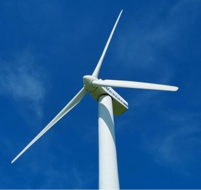
Wind Turbine Drip Loops: Can (N)TCEWÖU 3×95 survive the constant ±100°/m torsion inside a wind tower nacelle? Yes—by design. 风机下垂环:(N)TCEWÖU 3×95 能否承受风机机舱内持续的 ±100°/m 扭转?是的——按设计。
A comprehensive technical guide explaining the engineering principles that enable (N)TCEWÖU cables to survive continuous torsional cycling that would destroy conventional cables. This document teaches how cables can be designed to tolerate extreme twisting stresses by understanding the mechanics of torsion-induced fatigue, the role of stranding geometry and pitch in distributing torsional strain, and the critical function of special slip-facilitating tape constructions that allow conductor slippage during rotation. The (N)TCEWÖU designation itself encodes the cable’s purpose: it is engineered specifically for wind turbine nacelle applications where the yaw system continuously rotates the rotor to track wind direction, imposing ±100°/m torsional stress on the drip loop cable that connects the stationary tower to the rotating nacelle. Rather than attempting to prevent twisting through rigid mechanical design, the (N)TCEWÖU accomplishes torsion tolerance through materials science and cable construction that allows the conductors to slip and distribute stress evenly during rotation. This document explains the physics underlying this design philosophy, providing detailed technical specifications for (N)TCEWÖU including documented torsion resistance of ±100°/m with test cycle life exceeding two million cycles, low-temperature flexibility critical for cold-climate wind farms operating down to -35°C during dynamic twisting, and ampacity calculations accounting for the unique thermal environment of nacelle installations. Addresses practical field challenges including friction damage from cable movement during yawing cycles, conductor breakage from improperly de-twisted cable installation, accelerated degradation from oil contamination from leaking gearbox systems, and the critical importance of properly functioning twist limiters to prevent accumulation of permanent torsional deformation. The document establishes that (N)TCEWÖU cables represent specialized engineering solutions developed through decades of wind energy experience, not generic cables pressed into service for a harsh application.
1. Direct Answer: Yes, (N)TCEWÖU is Engineered for This Exact Challenge 直接答案:是的,(N)TCEWÖU 专为此挑战而设计
The straightforward answer to whether (N)TCEWÖU 3×95 cables can survive the constant ±100°/m torsional stress inside a wind tower nacelle is: yes, absolutely—this cable type is specifically engineered for exactly this application and has demonstrated performance exceeding two million torsion cycles without failure. The (N)TCEWÖU designation itself is not arbitrary—it explicitly identifies cables designed for wind turbine applications where continuous twisting from the yaw system is the defining operating condition. This cable type achieves torsion tolerance through a fundamentally different design philosophy than conventional cables. Rather than attempting to rigidly prevent any twisting through mechanical constraint, the (N)TCEWÖU accomplishes tolerance through materials science and cable construction that allows controlled slippage of conductors during rotation, distributing torsional stress evenly across all cable components and preventing the stress concentration that destroys conventional cables. Understanding how this engineering works requires studying the physics of torsion, examining why conventional cables fail under these conditions, and learning how (N)TCEWÖU’s special construction mitigates each failure mechanism.
The significance of this achievement cannot be overstated. A conventional medium-voltage cable subjected to ±100°/m of continuous torsional cycling would fail catastrophically within weeks to months, with conductor strands breaking and insulation cracking from the concentrated stress. A wind turbine nacelle rotates dozens of times per day to track wind direction, creating millions of torsion cycles over the 20–25 year design life of a wind farm installation. For wind energy to be practical, the cables connecting the rotating nacelle to the stationary tower must survive this entire service life without failure or degradation. The (N)TCEWÖU cable accomplishes this through engineered flexibility in torsional response, allowing the cable structure to adapt dynamically to twisting stresses rather than resisting them with rigid strength. This is not magical—it is applied physics and materials engineering, developed through decades of wind energy experience and refined through extensive laboratory testing. Learning to think about cables this way—understanding how design can address specific operating challenges through fundamental principles rather than through brute-force strength—is the key to becoming a truly competent cable engineer.
Why (N)TCEWÖU Succeeds Where Others Fail ✓ 为什么 (N)TCEWÖU 成功: The cable’s torsion tolerance comes from three integrated design elements working together. First, the conductor stranding uses a special helical pitch angle calculated to distribute torsional strain evenly rather than concentrating it. Second, the tape wrapping between conductor and insulation has deliberately high slip properties, allowing the conductors to rotate slightly relative to the outer layers during twisting, relieving stress concentration. Third, the elastomer compounds in the insulation and jacket are formulated with plasticizers and slip agents that allow molecular flexibility under torsional cycling rather than rigid resistance. These three elements together enable the cable to deform continuously under torsional stress without permanent damage or stress concentration, achieving performance that rigid designs cannot match. This is applied materials science at its finest.
2. Understanding Torsion: The Unique Stress Environment Inside Wind Turbine Nacelles 理解扭转:风机机舱内的独特应力环境
To appreciate why a cable must be specially engineered for wind turbine service, you must first understand the operating environment inside a wind tower nacelle and the unique stresses created by the yaw system. A wind turbine is a large rotating machine mounted on top of a tall tower. The rotor (consisting of the hub and three blades) rotates at approximately 10–20 revolutions per minute when generating power. However, the wind direction is constantly changing, and the rotor must continuously rotate about its vertical axis to face the oncoming wind. This rotation about the vertical axis is called yawing. The yaw mechanism, typically using electric motors and gears, rotates the entire nacelle (the housing containing the generator and gearbox) plus the rotor about the vertical tower axis. This yawing is not a slow, gentle motion. Modern wind turbines yaw aggressively, sometimes rotating through 30–60 degrees per minute to keep the rotor optimally aligned with wind direction.
Now imagine a cable that must connect the stationary tower (which is fixed and does not rotate) to the rotating nacelle (which yaws back and forth). The cable naturally gets twisted as the nacelle rotates. Every time the nacelle rotates one degree, the cable twists one degree. If the nacelle rotates through 180 degrees during a yaw maneuver, the cable twists 180 degrees. During a typical day with changing wind directions, a wind turbine might perform dozens of complete rotations (multiple 360-degree rotations back and forth). Over the course of a year, a wind turbine performs thousands of complete rotations. Over 20 years, this accumulates to millions of twisting cycles. The cable that connects the rotating nacelle to the stationary tower must survive all of this twisting without failing. This is the unique operating environment that (N)TCEWÖU cables are engineered to tolerate.
The magnitude of torsional stress in this environment is substantial. When a cable is twisted, the outer surface of the cable experiences compression while the inner components experience tension. For a relatively stiff cable, a twist of ±100°/m (which means a full 360-degree rotation every 3.6 meters of cable length) creates shear stress on the conductor strands and compressive stress on the insulation. If the cable is not specifically designed to tolerate this twisting, the conductor strands will eventually crack from fatigue, or the insulation will develop stress concentrations that lead to partial discharge and eventual failure.
3. Why Conventional Cables Fail Under Torsion: Learning From Failure Modes 为什么常规电缆在扭转下失败:从故障模式学习
To understand why (N)TCEWÖU is necessary, let’s examine what happens when conventional cables are subjected to torsional stress. A standard medium-voltage cable is engineered for bending, tension, and thermal stress, but not for continuous twisting. When such a cable is installed in a wind turbine nacelle and subjected to torsional cycling, specific failure mechanisms emerge that eventually lead to catastrophic failure.
The first failure mechanism is conductor strand fatigue. In a conventional cable, the conductor strands are twisted together in a fixed helical pattern designed for tensile strength and bending flexibility, but not for torsional stress. When the entire cable is twisted, the individual conductor strands experience alternating tensile and compressive stress. The copper in the conductor strands, while ductile, still has fatigue limits. After thousands of twisting cycles, microcracks develop in the most highly stressed strands. These microcracks propagate with each subsequent twisting cycle, eventually leading to complete strand fracture. A cable with multiple conductor strand fractures loses structural integrity and becomes a safety hazard.
The second failure mechanism is insulation cracking and partial discharge initiation. The insulation in a conventional cable is bonded to the conductor through the intermediate semi-conductive layer. When the cable twists, the insulation experiences internal shear stress as it tries to rotate with the twisting motion while the outer jacket resists rotation through friction with the cable clamps and supports. This internal shear creates localized stress concentrations in the insulation. After thousands of torsion cycles, small cracks develop at these stress concentration points. Once a crack is initiated, partial discharge (electrical micro-arcing) can begin within the crack, causing progressive insulation degradation and eventually complete breakdown.
The third failure mechanism is permanent plastic deformation and corkscrewing. Some conventional cables, under repeated torsional stress, develop permanent spiral deformation—a corkscrewing effect where the cable physically twists into a permanent helical shape. This deformation is irreversible and indicates that the molecular structure of the elastomers and the conductor stranding have been permanently damaged. A cable with permanent corkscrewing has lost its original structural properties and cannot be considered safe for service.
All three failure mechanisms have been observed in conventional cables installed in wind turbine applications before (N)TCEWÖU became the industry standard. The time to failure typically ranges from weeks to months depending on the specific cable type and the intensity of the torsional cycling. This demonstrates that conventional cables are fundamentally unsuitable for this application, and specially engineered cables are necessary.
4. The Physics of Torsional Stress on Cable Conductors 电缆导体上的扭转应力物理学
Now that you understand the failure modes that affect conventional cables, let’s examine the physics of torsional stress in detail. Understanding the underlying physics is essential to appreciating how (N)TCEWÖU’s design solves these problems.
When a cylindrical object like a cable is twisted, every element of the cable experiences a shear strain proportional to its distance from the cable’s central axis. Consider an imaginary grid drawn on the cable’s cross-section. When the cable twists, this grid deforms—elements near the outer surface shift more than elements near the center. The shear strain is defined as the angle through which the grid deforms divided by the distance from the center. For a cable experiencing ±100°/m of torsion, each meter of cable twists 100 degrees (or about 0.28 radians). This creates a shear strain distribution that is zero at the center and maximum at the outer surface.
The shear stress (force per unit area causing this deformation) depends on the shear modulus of the material—a property that describes how much resistance a material provides against shear deformation. Copper has a shear modulus of approximately 45 GPa, while rubber elastomers have shear moduli typically in the range of 0.5–2 MPa. The enormous difference in shear modulus between copper and rubber explains why torsional stress affects the two materials very differently. The copper conducts much higher stress, while the rubber allows much more deformation.
Here is where the engineering insight emerges: if you engineer a cable where the conductor is rigidly locked to the insulation (as in conventional cables), the torsional stress applied to the cable is transmitted directly to the conductor, which experiences high shear stress due to its high shear modulus and resulting low deformability. This concentrated stress in the conductor leads to the fatigue cracking mechanisms described earlier. However, if you engineer a cable where the conductor can slip slightly relative to the outer layers, the torsion can be distributed across multiple components, and no single component experiences the high concentration of stress that leads to fatigue. This is the fundamental principle behind (N)TCEWÖU’s design.
5. Cable Design Solutions: How (N)TCEWÖU Tolerates Continuous Twisting 电缆设计方案:(N)TCEWÖU 如何承受连续扭转
Having understood the physics of torsional stress, we can now examine how (N)TCEWÖU cables are designed to tolerate ±100°/m of continuous twisting. The design involves three integrated elements that work synergistically to distribute torsional stress and prevent the fatigue mechanisms that destroy conventional cables.
The first design element is special conductor stranding geometry. The conductor strands in an (N)TCEWÖU cable are arranged with a pitch angle (the angle at which the helical strands are twisted around the cable center) that is deliberately calculated to allow slip during torsional cycling. Rather than using a conventional tight stranding that resists any relative motion between strands, (N)TCEWÖU uses a more open stranding pattern where the strands can shift slightly relative to each other when torsional stress is applied. This allows the conductor as a whole to distribute torsional strain across all strands rather than concentrating stress in the most constrained strands. The specific pitch angle is proprietary to each cable manufacturer, but the principle is consistent: allowing slip distributes stress.
The second design element is the use of special slip-facilitating tape wrapping between the conductor and the insulation. Conventional cables use tight wrapping to ensure mechanical bonding between conductor and insulation. (N)TCEWÖU cables intentionally use tape with low adhesive properties or special surface treatments that deliberately maintain low friction. This allows the conductor to rotate slightly relative to the insulation during torsional cycling, relieving stress concentration at the conductor-insulation interface. The conductor can twist relative to the outer layers without propagating tensile stress to the insulation.
The third design element is the use of specially formulated elastomers in both the insulation and jacket. These compounds are engineered with particular plasticizers and slip agents that allow molecular chains to flex and reorient during torsional stress without permanent deformation. Rather than resisting twisting with rigid strength, these materials allow controlled deformation that distributes stress and prevents concentration. Additionally, the elastomers are formulated to recover quickly after torsional stress is removed, returning to their original configuration without permanent set.
These three elements working together create a cable that does not resist torsional stress through rigid strength, but rather accommodates torsional stress through controlled deformation and slip. This is the fundamental difference in engineering philosophy between conventional cables and (N)TCEWÖU cables. Understanding and accepting this design approach is essential to appreciating why (N)TCEWÖU succeeds where conventional cables fail.
6. Stranding Geometry and Pitch: Engineering Against Torsion-Induced Fatigue 绞合几何和节距:对抗扭转诱导疲劳的工程
Let’s delve deeper into the conductor stranding geometry, because this is where the fundamental torsion tolerance is engineered. In a conventional cable, the conductor strands are twisted together with a specific pitch (the distance along the cable axis required for one complete helical revolution). This pitch is optimized for tensile strength and bending flexibility. Typically, the pitch-to-diameter ratio is in the range of 8–12, meaning one complete helical revolution occurs over a distance equal to 8–12 times the conductor diameter.
For torsional stress, this conventional pitch geometry creates a problem. When the entire cable is twisted, the helically arranged strands experience not only the twisting motion of the cable as a whole, but also the geometric effect of their helical arrangement. The strands that are already arranged in a helical pattern experience additional strain when the entire cable twists. Some strands become more tightly wound, while others become more loosely wound. This non-uniform strain distribution leads to stress concentration in the most tightly wound strands, which is exactly the mechanism that causes fatigue cracking.
(N)TCEWÖU cables use a different stranding pitch that is optimized for torsional accommodation rather than tensile strength. The specific pitch is chosen such that when the cable twists at ±100°/m, the helical strands undergo a geometric rearrangement that partially cancels out the applied torsion. Rather than all strands experiencing uniform increase in twist, some strands increase in pitch while others decrease, distributing the torsional strain evenly. Additionally, the more open stranding pattern allows the strands to slip slightly relative to each other, further distributing stress. The result is a conductor that can undergo millions of twisting cycles without developing the stress concentrations that lead to fatigue cracking.
This is not magic—it is pure geometry and mechanics. The helical stranding pattern itself becomes the mechanism for accommodating torsional stress rather than concentrating it. Understanding this principle helps you appreciate why (N)TCEWÖU’s design is fundamentally different from conventional cables and why retrofitting conventional cables with (N)TCEWÖU connectors does not create an (N)TCEWÖU cable. The entire cable construction, from conductor stranding through insulation to jacket, must be engineered as an integrated system to achieve torsion tolerance.
7. The Critical Role of Slip-Facilitating Tape Constructions 滑动促进胶带结构的关键作用
The tape wrapping between conductor and insulation is perhaps the least understood component of (N)TCEWÖU cable design, yet it is absolutely critical to achieving torsion tolerance. Understanding this component requires recognizing that the tape serves a fundamentally different purpose in (N)TCEWÖU cables than it does in conventional cables.
In conventional cables, the tape wrapping between conductor and insulation serves to mechanically bond the conductor to the insulation while providing some semi-conductive properties for field grading. The tape is wrapped tightly and is designed to create strong adhesion. This tight adhesion is appropriate for cables subject to bending and tension, where you want the conductor and insulation to move together as a rigid unit.
In (N)TCEWÖU cables, the tape wrapping serves a different purpose: it must allow controlled slip between conductor and insulation while still maintaining electrical contact and semi-conductive properties. The tape in (N)TCEWÖU cables is formulated with low-adhesion compounds or has special surface treatments that deliberately reduce the friction between tape and insulation. When the cable twists, the conductor can rotate slightly relative to the outer insulation layers. The low-friction tape allows this relative motion without building up high friction forces. The slip is controlled—not unlimited—allowing just enough relative motion to distribute torsional stress without allowing complete separation of conductor from insulation.
The amount of allowable slip is carefully engineered. Too much slip would allow the conductor to rotate freely relative to the jacket, potentially creating internal frictional heating. Too little slip would concentrate stress at the conductor-insulation interface, defeating the purpose of the low-friction tape. The optimized slip amount is typically in the range of a few degrees of relative rotation per meter of cable length. This controlled slip distributes torsional stress from the conductor to the outer layers, relieving the concentration that would cause conductor fatigue.
This slip-facilitating tape construction is one of the elements that distinguishes genuine (N)TCEWÖU cables from conventional cables that might have similar conductors and insulation but lack the specialized tape. A cable with conventional high-adhesion tape cannot achieve the torsion tolerance of (N)TCEWÖU, regardless of the quality of other components. The entire construction, including the specific tape formulation, must be optimized for torsion tolerance.
8. Continuous Ampacity for (N)TCEWÖU 3×95 in Nacelle Service 机舱服务中 (N)TCEWÖU 3×95 的连续载流量
Having established the mechanical design principles that allow (N)TCEWÖU to tolerate torsion, we can now proceed to electrical analysis and ampacity calculation. The continuous ampacity of (N)TCEWÖU 3×95 cables at reference conditions is 290 amperes according to DIN VDE 0250-813, the European standard governing flexible cables for industrial applications including wind turbines.
The reference conditions assume 40°C ambient temperature and 90°C maximum permissible conductor temperature. These reference values represent typical conditions in a nacelle environment during moderate ambient conditions. The 290-ampere rating is the maximum continuous current that allows the conductor to remain at or below 90°C when operating in these reference conditions.
However, nacelle installations present specific thermal challenges that differ from fixed industrial installations. A nacelle is enclosed and has limited air circulation for cooling. During operation on a sunny day, the nacelle exterior temperature can reach 50–60°C, and the interior can reach 40–50°C. Additionally, the generator and gearbox in the nacelle generate substantial waste heat during power generation. The local temperature around the power cables can easily reach 45–55°C during operation, which is significantly higher than the 40°C reference condition.
This means that nacelle installations require temperature derating to account for the elevated local ambient. For a 45°C local ambient, the derating factor is approximately 0.94 (6% reduction). For a 50°C local ambient, the derating factor is approximately 0.89 (11% reduction). For a conservative design accounting for peak summer conditions and high equipment load, a 50°C ambient should be assumed, resulting in a design ampacity of approximately 290 × 0.89 ≈ 258 amperes for (N)TCEWÖU 3×95 in nacelle service.
This ampacity is typically adequate for the main power connections from nacelle to tower. Wind turbine nacelles typically require between 200–250 amperes of continuous current capacity during rated power generation. The 258-ampere derated design ampacity provides appropriate margin above typical power requirements.
9. Low-Temperature Performance: Critical for Cold-Climate Wind Farms 低温性能:冷气候风电场的关键
A critical aspect of (N)TCEWÖU cable performance that distinguishes it from many conventional cables is its ability to remain flexible and function during torsional cycling at extremely low temperatures. This is not merely a convenience—it is an essential requirement for wind farms in northern climates where temperatures regularly drop to -20°C or colder during winter operation.
Many elastomer compounds become brittle and lose flexibility at low temperatures. A conventional cable that performs well at room temperature might become dangerously stiff and prone to cracking when cooled to -20°C or lower. This is catastrophic for a wind turbine cable, because torsional cycling at low temperature creates even higher mechanical stress on already-brittle material. The (N)TCEWÖU cable is engineered with elastomer formulations that maintain flexibility even at -35°C during dynamic twisting, allowing the cable to continue tolerating torsional stress throughout the full range of temperatures encountered in cold-climate wind farm operation.
This low-temperature flexibility requires specific elastomer chemistry and the use of particular plasticizers that maintain molecular chain mobility even at extreme cold. The insulation and jacket formulations are significantly different from those used in conventional cables, reflecting the specialized requirements of wind turbine operation in harsh climates.
10. Mechanical Fatigue from Repetitive Torsion: Test Data and Life Predictions 重复扭转的机械疲劳:测试数据和寿命预测
The robustness of (N)TCEWÖU cables is not theoretical—it is demonstrated through extensive laboratory testing that simulates the torsional environment of wind turbine nacelles. Standard testing procedures expose cable samples to repetitive torsional cycling at amplitude and frequency representative of actual wind turbine duty, then assess whether the cable survives the test without electrical or mechanical failure.
The standard test protocol for (N)TCEWÖU cables imposes ±100°/m torsional cycling on cable samples and continues until either the cable fails electrically (insulation breakdown, conductor fracture) or until two million complete torsion cycles are completed. The vast majority of properly manufactured (N)TCEWÖU cables complete the full two million cycle test without failure, demonstrating that they can tolerate the torsional environment of a wind turbine nacelle for the entire 20–25 year design life of the installation.
To understand what two million cycles means in practical terms, consider a typical wind turbine that yaws several times per hour during normal operation. In a year of operation, the nacelle might perform 5,000–10,000 complete yaw rotations (each involving multiple 360-degree rotations back and forth). Over a 20-year design life, this accumulates to perhaps 100,000–200,000 complete yaw maneuvers. Each maneuver involves roughly 10–20 torsional cycles of the cable as the nacelle rotates back and forth. This results in approximately 1–4 million torsional cycles over the cable’s design life. The fact that (N)TCEWÖU cables demonstrate survival of two million test cycles in the laboratory provides confidence that they will survive the actual operational environment where the stressing is typically less severe than the accelerated laboratory test.
11. Field Problems, Installation Errors, and Operational Challenges 现场问题、安装错误和运行挑战
Despite (N)TCEWÖU’s excellent engineering, wind turbine installations occasionally encounter field failures and operational challenges. Understanding these common problems and their root causes helps prevent premature cable failure and ensures the cable can deliver its full design life.
11.1 Friction Damage from Cable Movement During Yawing Cycles 偏航循环期间电缆移动造成的摩擦损伤
As the nacelle yaws, the cables connecting the nacelle to the tower move and flex continuously. If the cable is not properly supported and guided, it can rub against sharp edges, move between support points, or oscillate against cable clamps and other hardpoints. Over thousands of yawing cycles, this rubbing can gradually wear through the jacket and expose the insulation underneath. Once the jacket is breached and insulation is exposed, moisture and contamination can penetrate, leading to insulation degradation and eventual electrical failure.
Prevention of this damage requires careful attention to cable routing and support design. Cables must be supported with proper cable grips and spacers that distribute mechanical stress evenly along the cable length. Cable stockings (protective sleeves) can be applied over the cable in areas of high friction risk to provide an additional protective layer. The cable routing should minimize sharp bends and rapid direction changes that create high friction points.
11.2 Premature Conductor Breakage from Residual Twist Stress 残余扭转应力造成的过早导体断裂
The most common installation error that leads to cable failure is installation of the cable with residual twist stress. When a cable is wound on a shipping reel at the factory, it acquires a residual twist from the manufacturing and coiling process. If the cable is not fully de-twisted before installation in the wind turbine, this residual twist remains locked into the cable structure. When the nacelle begins to yaw and applies additional torsional stress, the residual twist combines with the applied stress, potentially exceeding the cable’s tolerance limits.
Prevention requires strict discipline during installation. Before a cable is installed on a wind turbine, it must be completely unwound from its reel and allowed to hang freely or lay out straight on the ground for a minimum of 12–24 hours to fully relieve all residual twist stress. Only after complete de-twisting should the cable be routed into the wind tower. This seems like a time-consuming step, and it is, but it is absolutely essential to prevent premature failure from combined residual and operational torsional stress.
11.3 Oil Contamination from Gearbox and Hydraulic System Leaks 齿轮箱和液压系统泄漏造成的油污染
Wind turbine gearboxes and hydraulic systems are located in the nacelle in close proximity to the power cables. Leaking oil from these systems drips onto the cables and can accelerate degradation of the jacket and insulation. While (N)TCEWÖU cables are formulated to resist oil exposure better than conventional cables, the terminations (where the cable connects to equipment) are often the weak points. Oil can penetrate into the termination area where the external jacket ends and custom connector compounds begin.
Prevention requires prompt repair of any leaking gearbox or hydraulic systems and regular cleaning of cable terminations to remove accumulated oil. Additionally, protective sleeves can be applied over cable terminations to exclude oil and direct any leakage away from the connection points.
12. Proper Installation and Maintenance Procedures for Long Cable Life 延长电缆寿命的正确安装和维护程序
Achieving the full 20–25 year design life that (N)TCEWÖU cables are capable of requires attention to proper installation and ongoing maintenance procedures throughout the cable’s service life.
12.1 De-Twisting Protocol Before Installation 安装前的退扭程序
When a cable is delivered to the wind farm site, the first step must be complete de-twisting. The cable should be removed from its shipping reel and allowed to hang freely from a support structure (or laid out horizontally on a clean surface) for at least 12–24 hours before installation. During this period, the residual twist accumulated during manufacturing will naturally relax and dissipate. The cable will gradually untwist itself as the elastomer materials relax and release the stored torsional energy. Only after complete de-twisting is complete should the cable be routed into the tower and connected to equipment.
12.2 Cable Routing and Support Design 电缆布线和支撑设计
The routing path of the cable through the nacelle and tower should be designed to minimize tight bends, avoid sharp edges, and distribute support points evenly. The cable should be supported with proper cable grips that apply clamping force evenly across the cable width rather than concentrating force at a single line of contact. Cable spacers should be used to maintain physical separation between multiple cables, preventing them from bundling together and creating friction between them.
12.3 Twist Limiter Function and Periodic Verification 扭转限制器功能和定期验证
Modern wind turbines incorporate mechanical twist limiters in the yaw system that prevent the nacelle from rotating more than a certain number of degrees in either direction, ensuring that the cable cannot be twisted beyond safe limits. These twist limiters must be periodically inspected and tested to verify they function correctly. If a twist limiter fails and allows unlimited nacelle rotation, the cable can accumulate twist in one direction until the strain exceeds the cable’s tolerance, leading to failure.
12.4 Regular Cable Inspection and Preventive Cleaning 定期电缆检查和预防性清洁
Throughout the cable’s service life, periodic inspections should examine the cable jacket for signs of damage, wear, or contamination. Any visible damage to the jacket should be repaired promptly with appropriate protective sleeves. Cable terminations should be cleaned periodically to remove accumulated oil, dirt, or salt spray (in coastal locations) that could accelerate degradation. Maintenance logs should document the condition of the cable and any repairs or cleaning performed, providing a record of the cable’s condition over its service life.
References & Standards 参考文献与标准
- DIN VDE 0250-813 — “Heavy-Duty Flexible Rubber-Sheathed Cables.” German standard establishing specifications for flexible industrial cables including (N)TCEWÖU types for wind turbine applications, with detailed requirements for torsion resistance testing and mechanical fatigue life.
- IEC 60811-1-2 — “Tests on Cables Under Fire Conditions — Part 1-2: Vertical Flame Test.” International standard for fire testing procedures that wind turbine cables must meet to ensure safety in nacelle fires.
- IWES (Fraunhofer Institute for Wind Energy Systems) Technical Guidelines — Leading German research institute developing wind turbine technical standards, including detailed specifications for nacelle cable requirements and torsion tolerance specifications.
- GL Germanischer Lloyd Rules and Guidelines — Classification society providing detailed certification requirements for wind turbine electrical systems including cable specifications and testing procedures for torsion resistance.
- IEC 61400-1 — “Wind Turbines — Part 1: Design Requirements.” International standard for wind turbine design including electrical safety requirements for internal nacelle cables and torsion environment specifications.
- (N)TCEWÖU Technical Data Sheet — Manufacturer specifications including conductor properties, ampacity ratings, torsion resistance data from laboratory testing, low-temperature performance characteristics, and installation procedures for wind turbine applications.
Contact Feichun Cable Technical Support 联系飞纯电缆技术支持
For (N)TCEWÖU 3×95 and other wind turbine torsion cable specifications, nacelle drip loop power system design, torsion resistance verification and testing, ampacity calculations for wind turbine duty cycles, low-temperature performance analysis for cold-climate installations, cable routing and support design consultation, installation procedure development and de-twisting protocols, periodic inspection and maintenance procedure development, twist limiter coordination and safety system design, or comprehensive technical documentation for wind farm electrical system approvals and certification, contact our technical engineering team. We provide detailed ampacity calculations per DIN VDE 0250-813 standards, wind-turbine-specific engineering analysis accounting for torsional stress and thermal environments, certification support for major wind turbine OEMs and classification societies, field testing and verification procedures, and complete installation and maintenance documentation for reliable long-term cable performance in wind energy applications. 对于风机电缆的选型、扭转载流量计算或现场安装验证,请直接联系我们的技术团队。


