
Technical Deep Dive — Marine & Offshore Cable Engineering
What Makes AmerCable GEXOL® Type P Cables More Flexible and Vibration-Resistant Than Standard Type MC Cables?
A data-driven engineering analysis of the Nexans AmerCable 37-102 Series GEXOL® single-conductor power cable — examining the material science, strand architecture, and IEEE 1580 Type P compliance parameters that deliver superior flexibility and vibration endurance in offshore drilling, marine vessel, and petrochemical installations.
1. Introduction & Market Context
In harsh industrial environments — particularly offshore drilling platforms, FPSO vessels, and petrochemical plants — cable failure due to mechanical fatigue is one of the leading causes of unplanned downtime. According to research cited by the IEEE Power & Energy Society, vibration-induced conductor fracture accounts for a significant portion of cable failures in dynamically loaded installations. This reality drives demand for cables that can endure sustained mechanical stress while maintaining electrical integrity across wide temperature ranges.
The Nexans AmerCable 37-102 Series, built on the proprietary GEXOL® cross-linked flame-retardant polyolefin insulation system, is a single-conductor power cable engineered precisely for these conditions. Classified as IEEE 1580 Type P, it represents a fundamentally different design philosophy from conventional Type MC (Metal-Clad) cables. While both cable families serve power distribution functions, the underlying material chemistry, strand geometry, and qualification standards diverge significantly — and those differences translate directly into measurable performance advantages in flexibility and vibration resistance.
As noted in the marine cable engineering resources provided by ReelingCable.com, cables deployed in reeling, unreeling, and continuous-motion applications require extraordinarily high strand counts and advanced insulation compounds to survive millions of flex cycles without degradation. This is precisely the engineering domain where GEXOL® Type P cables excel and where standard Type MC constructions typically fall short.
This article — compiled by the technical engineering team at Anhui Feichun Special Cable Co., Ltd. (安徽飞纯特种电缆有限公司) — provides a comprehensive, parameter-driven analysis of the 37-102 Series to help electrical engineers, procurement specialists, and marine inspectors make informed cable selection decisions.
2. Purpose & Application Scope
The 37-102 Series cable is designed as a 600V / 2kV rated single-conductor power cable for use in environments where extreme mechanical stress, chemical exposure, and fire safety are concurrent requirements. Unlike general-purpose industrial cables that prioritize cost efficiency in static installations, the Type P designation under IEEE 1580 specifically mandates performance in dynamic, vibration-intensive, and high-temperature applications.
Primary Application Domains
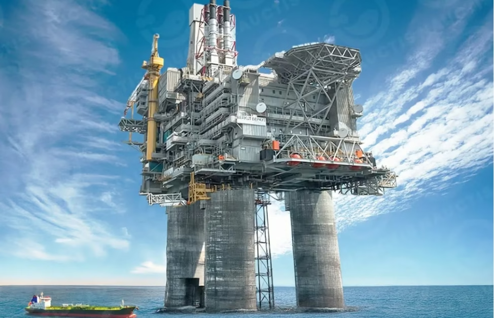
The cable’s design targets several overlapping industrial sectors. In offshore oil and gas — including drilling rigs, production platforms, and FPSO vessels — the cable is used for motor feeder circuits, auxiliary power distribution, and equipment connections in engine rooms and drilling floors where continuous vibration from rotating machinery is present. Technical resources from Amplex Mining confirm that mining and offshore operations share similar demands for cables that maintain conductor integrity under sustained mechanical loading.
In marine and shipboard installations, the cable serves primary and secondary power distribution circuits aboard commercial vessels, naval ships, and floating production units. The IEEE 1580 Type P classification, combined with ABS, DNV, and Lloyd’s Register certifications, qualifies it for installation in machinery spaces, deck equipment circuits, and navigation system power feeds. For crane and material handling systems aboard vessels and at port facilities, resources from CraneCable.com highlight the critical importance of high-flex cable construction in preventing downtime during cargo operations.
The cable also serves petrochemical processing plants where hazardous area classification (Class I, Division 1 / Zone 1) demands cables capable of maintaining integrity in explosive atmospheres when installed with appropriate armor and gland systems. Mining applications, as documented by MiningCable.cl, present similarly demanding conditions where cable flexibility and environmental resistance are paramount for operational safety and continuity.
3. Flexibility Analysis: Type P vs. Type MC
The fundamental difference in flexibility between GEXOL® Type P and standard Type MC cables stems from three engineering factors working in concert: conductor strand count and strand diameter, insulation material modulus of elasticity, and overall construction geometry. Understanding each factor quantitatively reveals why Type P cables outperform in dynamic applications.
3.1 Conductor Strand Architecture
Standard Type MC cables typically use Class B stranding as defined by ASTM B8 / B174, with strand counts ranging from 7 strands (for smaller gauges) to 61 strands (for larger gauges). In contrast, the GEXOL® Type P construction uses high-strand-count, soft-annealed, tin-plated copper conductors, often employing Class K or even higher flexibility classifications with strand counts that can exceed several hundred individual wires for larger cross-sections. The individual strand diameter drops below 0.10 mm in many configurations, dramatically reducing the bending stiffness which is proportional to the fourth power of individual wire diameter (per beam theory, I ∝ d⁴).
This mathematical relationship is critical: halving the individual wire diameter reduces the second moment of area (and thus bending stiffness) of each strand by a factor of 16. For a given overall conductor cross-section, using many fine strands instead of fewer coarse strands produces a cable that is dramatically easier to route, form, and install — and, more importantly, one that can survive millions of flex cycles without individual strand fracture. According to NEMA WC 70 (Power Cables Rated 2000 Volts or Less), conductor flexibility class directly correlates with the cable’s suitability for applications involving repeated bending.
3.2 Insulation Modulus Comparison
The GEXOL® cross-linked polyolefin insulation system has a notably lower modulus of elasticity compared to the PVC or XLPE compounds commonly used in standard Type MC cable jackets. A lower modulus means the insulation deforms more readily under bending stress and returns to its original shape without permanent set. This property is quantified by the insulation’s elongation at break (typically >300% for GEXOL® versus 150–200% for standard PVC) and its tensile strength retention after aging as tested per UL 44 / UL 1581 protocols.
⚡ GEXOL® Type P (37-102 Series)
Standard Type MC (Typical)
3.3 Vibration Resistance Mechanism
Vibration resistance in power cables is not merely a function of “softness” — it is a fatigue-life engineering problem. When a cable is subjected to continuous vibratory loading (such as from a marine diesel engine at 600–1800 RPM or a drawworks motor on a drilling rig), each conductor strand experiences alternating tensile and compressive stresses at the micro-level. According to the ASTM E466 fatigue testing standard framework, the endurance limit of a metallic conductor depends on its surface condition, residual stress state, and the amplitude of cyclic strain imposed on it.
Soft-annealed copper, as used in the GEXOL® Type P construction, has significantly lower residual stress and higher ductility than hard-drawn or semi-hard copper. Combined with tin plating (which prevents surface oxide formation that can act as stress concentrators), the individual strands exhibit fatigue lives that are typically 3–5× longer than those of harder, coarser strands under equivalent vibratory conditions. Furthermore, because the high strand count allows individual wires to move relative to each other within the conductor bundle, the cable effectively acts as a damped system rather than a rigid beam — absorbing vibratory energy through inter-strand friction rather than transmitting it as concentrated stress. The interlocked armor common in Type MC cables, by contrast, creates a rigid outer shell that transmits vibration directly to the conductor, accelerating fatigue failure.
4. Material Structure & GEXOL® Insulation Technology
The GEXOL® insulation system is a proprietary cross-linked flame-retardant polyolefin compound developed by Nexans AmerCable. Unlike PVC-based insulation systems that rely on plasticizers (which can migrate and stiffen over time) or conventional XLPE (which achieves flame retardance through halogenated additives), GEXOL® achieves its performance through a halogen-free, cross-linked molecular structure that intrinsically provides low smoke, low toxicity, and low corrosivity in fire conditions while maintaining excellent dielectric properties.
4.1 Layer-by-Layer Construction
The 37-102 Series cable, in its non-armored configuration, consists of three primary layers. The conductor is formed from high-strand-count, soft-annealed, tin-plated copper wire bundles with a lay length optimized for maximum flexibility. Each strand is typically tinned to a minimum thickness per ASTM B33, providing corrosion protection in marine atmospheres and reducing inter-strand oxidation bonding that would otherwise reduce flexibility over time. The GEXOL® insulation layer is applied by extrusion and then cross-linked (typically via a silane or peroxide process), creating a thermoset material that will not melt or flow at elevated temperatures — a critical safety property for the 110°C continuous operating rating. Finally, the GEXOL® outer jacket provides mechanical protection, abrasion resistance, and an additional flame-retardant barrier. In armored variants, a layer of galvanized steel or bronze armor is applied between the insulation and the outer jacket per the requirements of IEEE 1580 and the applicable marine classification society.
4.2 Dielectric Performance
GEXOL® cross-linked polyolefin exhibits a dielectric constant (εr) in the range of 2.3–2.5 at 1 kHz — significantly lower than PVC (εr ≈ 4.0–8.0) and comparable to unfilled XLPE (εr ≈ 2.3). This low dielectric constant results in lower capacitive charging currents, reduced dielectric heating losses, and higher insulation resistance values. Per IEC 60092-353 (Shipboard power cables with halogen-free insulation), the insulation resistance of GEXOL®-insulated cables typically exceeds 1000 MΩ·km at 20°C — well above the 100 MΩ·km minimum commonly specified for marine service.
Cross-linking transforms the polyolefin insulation from a thermoplastic (which softens when heated) into a thermoset (which maintains structural integrity at elevated temperatures). This is what enables the 110°C continuous operating temperature — approximately 20–35°C higher than standard PVC-insulated MC cables. The cross-linked molecular network also resists solvent attack, oil absorption, and environmental stress cracking, all of which are common failure modes in petrochemical and marine environments. For detailed cross-linking process analysis, see IEEE Transactions on Dielectrics and Electrical Insulation.
5. Electrical & Physical Parameters
The following table presents the core technical parameters for the 37-102 Series single-conductor, non-armored cable across its standard AWG range. All metric conversions from original AWG/kcmil specifications have been calculated to engineering precision. Theoretical copper weights are estimated from nominal conductor cross-sectional area and copper density (8,890 kg/m³), as the manufacturer’s published data sheets typically report only total cable weight.
| Cores × Area | AWG | Outer Ø (mm) | Cu Weight (kg/km) | Total Weight (kg/km) | Ampacity @ 110°C * |
|---|---|---|---|---|---|
| 1 × 1.0 mm² | 18 AWG | 2.92 | ~8.9 | 16.4 | 17 A |
| 1 × 1.3 mm² | 16 AWG | 3.18 | ~11.6 | 20.8 | 25 A |
| 1 × 2.1 mm² | 14 AWG | 4.17 | ~18.7 | 29.8 | 40 A |
| 1 × 3.3 mm² | 12 AWG | 4.75 | ~29.3 | 41.7 | 48 A |
| 1 × 5.3 mm² | 10 AWG | 5.28 | ~47.1 | 61.0 | 62 A |
| 1 × 8.4 mm² | 8 AWG | 6.60 | ~74.7 | 93.8 | 77 A |
| 1 × 13.3 mm² | 6 AWG | 7.37 | ~118.2 | 154.8 | 102 A |
* Ampacity values based on: 110°C conductor temperature, single-layer installation in free air, 45°C ambient temperature, per IEEE 1580 / UL 1309 methodology. For dual-layer (stacked) installation or operation under ABS 100°C / DNV 95°C thermal limits, apply the appropriate derating factors (see Section 7).
5.1 Voltage Rating Detail
The voltage rating of the 37-102 Series varies by conductor gauge. Sizes 18 AWG through 10 AWG carry a 600V rating, while sizes 8 AWG and larger are rated for 2kV (with an IEC equivalent of 1000V). This dual-rating structure reflects the increased insulation wall thickness applied to larger gauges, which provides sufficient dielectric withstand for medium-voltage classification while maintaining the flexibility advantage of the GEXOL® compound. The voltage withstand test is performed per IEEE 1580 at 2.5× rated voltage for 5 minutes with no breakdown.
5.2 Weight Efficiency Analysis
An informative metric for cable engineers is the copper fill ratio — the proportion of the cable’s total mass that is functional conductor material. For the 37-102 Series, this ratio ranges from approximately 54% (for 18 AWG) to 76% (for 6 AWG), indicating that the GEXOL® insulation and jacket system adds comparatively minimal mass overhead. By comparison, armored Type MC cables typically exhibit copper fill ratios of 30–50% due to the additional weight of the steel interlocked armor. This weight difference is operationally significant on offshore platforms where weight budgets are strictly controlled and every kilogram of cable tray loading matters.
| AWG Size | Cu Weight (kg/km) | Total Weight (kg/km) | Cu Fill Ratio (%) | Typical MC Cu Fill (%) |
|---|---|---|---|---|
| 18 AWG | 8.9 | 16.4 | 54.3% | ~30–35% |
| 16 AWG | 11.6 | 20.8 | 55.8% | ~32–38% |
| 14 AWG | 18.7 | 29.8 | 62.8% | ~35–40% |
| 12 AWG | 29.3 | 41.7 | 70.3% | ~38–42% |
| 10 AWG | 47.1 | 61.0 | 77.2% | ~40–45% |
| 8 AWG | 74.7 | 93.8 | 79.6% | ~42–48% |
| 6 AWG | 118.2 | 154.8 | 76.4% | ~45–50% |
Cu Fill Ratio = (Theoretical Cu Weight / Total Cable Weight) × 100. Type MC values are typical ranges for interlocked armor construction and will vary by manufacturer.
6. Standards Compliance & Certifications
The 37-102 Series cable carries one of the most comprehensive certification portfolios in the marine and industrial cable market. Each standard addresses specific performance domains, and understanding the scope of each certification helps engineers verify that the cable meets the regulatory requirements of their specific installation jurisdiction and classification society.
| Standard / Certification | Scope | Key Requirement |
|---|---|---|
| IEEE 1580 Type P | Marine shipboard cable | Flame, flexibility, oil resistance, temperature rating |
| UL 1309 / CSA 245 | Marine shipboard cable — Type X110 | 110°C rating, flame test, wet dielectric withstand |
| IEC 60332-3 Cat. A | Vertical flame propagation (bunched cables) | Self-extinguishing within limits; char length < 2.5 m |
| IEEE 1202 | Flame testing — vertical cable tray | Equivalent to FT4 / CSA C22.2 No. 0.3 |
| CSA Cold Bend / Cold Impact | Low-temperature mechanical integrity | Cold bend at −40°C; cold impact at −35°C |
| ABS (American Bureau of Shipping) | Marine classification | Type approval for shipboard installation |
| DNV (Det Norske Veritas) | Marine classification | Type approval per DNV-OS-D201 |
| LRS (Lloyd’s Register) | Marine classification | Type approval for shipboard & offshore |
| Class I, Division 1 | NEC hazardous location | Suitable for explosive gas atmospheres (with armor) |
| Zone 1 (IECEx) | ATEX / IECEx hazardous area | Suitable for Zone 1 installation (with armor + gland) |
The simultaneous compliance with IEEE 1580 Type P and UL 1309 Type X110 means this cable satisfies both the USCG (United States Coast Guard) and international maritime requirements without needing separate cable types for different jurisdictional inspections — a significant procurement and logistics simplification for global fleet operators.
7. Safety Thresholds & Ampacity Derating
While the published ampacity values in Table 1 represent the cable’s maximum current-carrying capacity under ideal conditions (110°C conductor, 45°C ambient, single-layer free-air installation), real-world installations frequently require derating to account for higher ambient temperatures, cable bundling, enclosed installations, or classification society thermal limits. Understanding and correctly applying derating factors is essential for both safety and regulatory compliance.
7.1 Ambient Temperature Derating
The base ampacity values assume a 45°C ambient environment. For installations where ambient temperatures exceed this threshold — common in engine rooms (50–55°C), equatorial regions, or near heat sources — the ampacity must be reduced. The correction factor follows the relationship: I_corrected = I_base × √[(T_max − T_amb_actual) / (T_max − T_amb_base)], where T_max is 110°C and T_amb_base is 45°C. For example, at a 55°C ambient, the correction factor becomes √[(110−55)/(110−45)] = √(55/65) ≈ 0.919, meaning the 6 AWG cable’s ampacity drops from 102 A to approximately 93.7 A.
| Ambient Temp (°C) | Correction Factor | 6 AWG Derated Ampacity (A) | 10 AWG Derated Ampacity (A) |
|---|---|---|---|
| 35°C | 1.074 | 109.5 A | 66.6 A |
| 40°C | 1.038 | 105.9 A | 64.4 A |
| 45°C (base) | 1.000 | 102.0 A | 62.0 A |
| 50°C | 0.960 | 97.9 A | 59.5 A |
| 55°C | 0.919 | 93.7 A | 57.0 A |
| 60°C | 0.877 | 89.5 A | 54.4 A |
7.2 Classification Society Thermal Limits
When operating under ABS rules, the maximum conductor temperature is typically derated to 100°C (rather than the cable’s full 110°C rating), and under DNV rules, to 95°C. These lower thermal ceilings further reduce the permissible ampacity. The DNV 95°C derating is approximately 0.877× of the 110°C-based ampacity, while the ABS 100°C derating is approximately 0.919×. Both factors must be applied in addition to any ambient temperature corrections.
7.3 Grouping / Bundling Factors
When cables are installed in groups (multiple single-conductor cables in a common tray or conduit), mutual heating reduces each cable’s ampacity. For two single-conductor cables touching on a tray, a typical grouping factor of 0.85–0.90 applies. For three or more cables in a single layer, the factor drops to 0.75–0.85 depending on spacing. Dual-layer (stacked) installations require more aggressive derating, typically 0.65–0.75. Always consult the applicable classification society rules (ABS, DNV, or LRS) and the cable manufacturer’s installation guide for the exact grouping factors applicable to the specific tray configuration.
8. Installation & Use Precautions
Proper installation practices are essential to realizing the full performance potential of GEXOL® Type P cables. Even the most advanced cable construction can be compromised by improper handling, termination, or routing. The following precautions reflect both manufacturer recommendations and field best practices compiled from offshore installation experience shared by industry resources including ReelingCable.com and CraneCable.com.
8.1 Minimum Bend Radius
Although the GEXOL® Type P cable is classified as “extremely flexible,” it still has a minimum bend radius that must be respected during installation. For the non-armored 37-102 Series, the minimum bend radius is typically 4× the overall cable diameter during installation and 4× OD in the final installed position. For armored variants, this increases to 6–8× OD. Bending the cable tighter than these limits can cause permanent deformation of the insulation, reduce dielectric withstand capability, and initiate premature conductor fatigue. During cold-weather installation (below 0°C but above −40°C), the cable should be warmed to at least 0°C before bending to prevent cracking of the outer jacket.
8.2 Pulling Tension Limits
Maximum pulling tension during installation should not exceed the manufacturer’s specified limits, typically calculated as 8 N/mm² of total conductor cross-sectional area for copper conductors. For a 6 AWG (13.3 mm²) cable, this yields a maximum pulling tension of approximately 106 N (≈ 24 lbf). Exceeding this limit can stretch individual strands beyond their elastic limit, creating localized necking that becomes a hot spot under load.
8.3 Termination & Gland Selection
For hazardous area installations (Class I Division 1 / Zone 1), the cable must be terminated with appropriately certified cable glands that maintain the integrity of the hazardous area barrier. The gland must be suitable for the cable’s outer diameter range and must compress the outer jacket sufficiently to create a gas-tight seal without damaging the GEXOL® material. As technical guidance from Amplex Mining emphasizes, proper gland torque values are critical — over-torquing can crack the cable gland body or damage the jacket, while under-torquing can allow ingress of explosive atmospheres.
8.4 Chemical Compatibility
While GEXOL® polyolefin offers excellent resistance to most oils, fuels, and chemical splashes encountered in marine and petrochemical environments, prolonged immersion in certain aromatic solvents (toluene, xylene) or chlorinated hydrocarbons can cause swelling or softening. Cable routing should avoid areas where such chemicals may pool or accumulate. For installations in mining environments, additional consideration should be given to abrasion protection in areas with moving equipment or falling rock.
Do not use standard PVC cable ties directly on GEXOL® jackets under sustained tension — the PVC plasticizer can migrate into the polyolefin over time, causing localized softening. Use polyolefin, nylon, or stainless-steel cable ties instead. Do not paint over the GEXOL® jacket with solvent-based paints, which can attack the polyolefin surface. Use only water-based or manufacturer-approved marking systems.
9. Frequently Asked Questions
In many cases, yes — but with caveats. GEXOL® Type P cable (non-armored) can replace Type MC in applications where the metal armor is not required by code for physical protection or grounding continuity. In NEC Class I Division 1 hazardous locations, the Type P cable must be installed with an approved armor and gland system to maintain the hazardous area barrier. Always verify with the local AHJ (Authority Having Jurisdiction) and the applicable classification society before substituting cable types. The reduced weight and increased flexibility of the Type P cable often simplifies installation even in retrofit scenarios.
When installed and operated within its rated parameters (110°C max conductor temperature, minimum bend radius respected, appropriate derating applied), the GEXOL® insulation system is engineered for a service life exceeding 30 years based on Arrhenius thermal aging projections per IEEE 1580 / IEC 60216 methodology. The cross-linked polyolefin insulation does not suffer from the plasticizer migration and embrittlement that limits PVC cables to approximately 15–20 years in the same environments. Actual service life depends on installation conditions, loading patterns, and environmental exposure.
The non-armored 37-102 Series is not specifically designed for direct burial or continuous submersion. While the GEXOL® material offers good moisture resistance and passes wet dielectric withstand testing per UL 1309, direct burial applications require cables with specific crush resistance and soil compatibility ratings. For underwater or continuously submerged applications, Nexans AmerCable offers armored variants with additional moisture barriers. Consult the manufacturer’s application engineering team or contact Anhui Feichun Cable for cable selection guidance for specific submersion scenarios.
While both GEXOL® and standard XLPE are cross-linked polymers, they differ in base resin chemistry and additive systems. GEXOL® uses a proprietary polyolefin blend that is inherently halogen-free and flame-retardant without requiring halogenated additives. Standard XLPE relies on polyethylene cross-linking and typically requires halogenated flame-retardant additives (such as chlorinated or brominated compounds) to achieve comparable flame test ratings. In a fire, GEXOL® produces significantly less toxic and less corrosive smoke than halogenated XLPE — a critical safety advantage in enclosed marine and offshore environments where crew evacuation paths may be compromised by smoke. Additionally, GEXOL® exhibits lower water absorption and better flexibility retention after thermal aging compared to standard industrial XLPE compounds.
Vibration-induced cable failure is one of the most common causes of unplanned electrical outages on offshore platforms and vessels. Each failure event incurs direct costs (replacement cable, electrician labor, cable tray access) and indirect costs (production downtime, potential safety incidents, classification society re-inspection). By extending the fatigue life of the conductor by a factor of 3–5× compared to standard Type MC construction, GEXOL® Type P cables can reduce vibration-related cable replacement frequency from every 5–8 years to every 15–25+ years in severe-vibration environments. For a typical offshore platform with hundreds of motor circuits, this translates to substantial lifecycle cost savings. For operational efficiency data on flexible cable deployments, see industry case studies from ReelingCable.com and Amplex Mining.
The voltage rating is determined by the insulation wall thickness relative to the conductor size. In the 37-102 Series, sizes 18 AWG through 10 AWG (1.0 mm² to 5.3 mm²) carry a 600V rating, while 8 AWG and larger (8.4 mm² and above) are rated for 2kV (with an IEC equivalent of 1000V). Both voltage classes use the same GEXOL® insulation compound, but the 2kV versions have a thicker insulation wall to provide the required dielectric margin. The voltage withstand test is performed at 2.5× rated voltage for 5 minutes per IEEE 1580. For 600V cables this means a 1500V test; for 2kV cables, a 5000V test.
10. Source Quality GEXOL® Type P Cable — Contact Us
Anhui Feichun Special Cable Co., Ltd. (安徽飞纯特种电缆有限公司) is a specialist supplier of high-performance marine, offshore, and industrial cables, including the Nexans AmerCable 37-102 GEXOL® Type P series. Our engineering team provides technical support for cable selection, ampacity calculations, derating analysis, and installation planning for projects worldwide.
Request a Technical Quotation
Our cable engineers are available to help you select the right GEXOL® Type P cable configuration for your project. Contact us for datasheets, MOQ information, lead times, and competitive pricing.
For more information on specialized cable solutions for reeling, crane, mining, and offshore applications, explore our partner resources: ReelingCable.com, AmplexMining.com.au, MiningCable.cl, CraneCable.com, and FeichunCable.com.
Related Tags


