
Premium Highly Flexible Mining Reeling Cable with Individual Copper Braid Earth Conductor
What is a Type (N)TSCGECEWÖU 3,6/6 – 12/20 kV MT MIN-E PLUS Mining Cable?
Premium Highly Flexible Mining Reeling Cable with Individual Copper Braid Earth Conductor
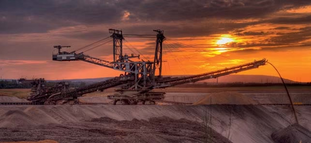
The (N)TSCGECEWÖU MT MIN-E PLUS represents the pinnacle of mining cable engineering, combining premium-grade materials with advanced construction techniques to deliver exceptional flexibility, enhanced safety, and superior durability for the most demanding opencast mining operations. This cable is specifically designed for heavy mobile equipment including draglines, electric shovels, dredges, and blast hole drills operating under extreme mechanical stresses and severe abrasion conditions.
The “MT MIN-E PLUS” designation signifies this cable’s premium status, featuring an innovative individual copper braid earth conductor system that provides both exceptional electrical safety and enhanced mechanical flexibility compared to standard mining cables. Manufactured to the exacting standards of DIN VDE 0250 Part 813, this cable delivers reliable performance in the harshest mining environments worldwide.
🌟 Premium MT MIN-E PLUS Features
The MT MIN-E PLUS variant offers superior characteristics that distinguish it from standard mining cables:
- Individual Copper Braid Earth Conductor: Bare copper wire braid construction provides 360° electromagnetic shielding and flexible grounding
- Enhanced Flexibility: Superior bending characteristics enable tighter routing in confined spaces
- Improved Safety Profile: Copper braid earth conductor offers immediate fault detection and protection
- Optimized Weight-to-Performance Ratio: Maximum tensile load of 15 N/mm² with reduced overall cable weight
- Double 5GM5 Sheath System: Both inner and outer sheaths use premium abrasion-resistant compound
1. Purpose and Applications
Primary Purpose
The (N)TSCGECEWÖU MT MIN-E PLUS cable serves as an advanced power transmission solution for heavy mobile mining equipment where three critical factors converge: maximum flexibility for complex cable routing, enhanced electrical safety through superior earth conductor design, and exceptional durability for extreme abrasion environments. The individual copper braid earth conductor provides both mechanical protection and superior electrical grounding characteristics essential for modern mining safety standards.
Target Equipment and Applications
This premium cable is engineered for the following high-value mining equipment:
Walking Draglines
Power Requirements: 6/10 kV to 12/20 kV, 70mm² to 150mm²
Large capacity walking draglines benefit from enhanced flexibility for complex cable management during bucket swing operations
Electric Rope Shovels
Power Requirements: 8,7/15 kV to 12/20 kV, 50mm² to 120mm²
High-capacity shovels require superior cable flexibility during dig-hoist-swing cycles
Floating Dredges
Power Requirements: 6/10 kV to 8,7/15 kV, 35mm² to 95mm²
Marine dredging operations benefit from copper braid’s corrosion resistance and EMI shielding
Rotary Blast Hole Drills
Power Requirements: 8,7/15 kV to 12/20 kV, 70mm² to 120mm²
Heavy-duty drilling equipment requires cable that withstands extreme vibration and frequent repositioning
Unique Application Advantages
The MT MIN-E PLUS cable provides specific advantages in challenging applications:
- High-Temperature Mining Environments: Superior heat dissipation through copper braid earth conductor extends service life in hot climate mining operations
- Wet Mining Operations: Bare copper braid provides consistent grounding even in saturated conditions while maintaining corrosion resistance
- Electromagnetic Interference (EMI) Sensitive Applications: Copper braid earth acts as comprehensive EMI shield, critical for equipment with sensitive electronic control systems
- Tight Routing Requirements: Enhanced flexibility allows cable installation in constrained spaces on modern compact mining equipment
- High-Value Equipment Protection: Superior fault detection capabilities protect expensive mining equipment from electrical damage
Industry Sectors
- Large-Scale Coal Mining: High-capacity surface mines with modern, electronically-controlled equipment
- Precious Metal Mining: Gold, silver, and platinum operations where equipment reliability is paramount
- Copper and Iron Ore: Large open-pit operations with ultra-class mining equipment
- Oil Sands Extraction: Bitumen mining operations requiring cables resistant to petroleum products
- Diamond Mining: High-value operations where equipment downtime costs are extreme
Why Choose MT MIN-E PLUS?
Select this premium cable when your mining operation demands:
- Maximum equipment uptime and reliability
- Enhanced electrical safety with superior earth conductor performance
- Improved flexibility for modern equipment with compact cable routing
- EMI shielding for sensitive electronic control systems
- Extended service life in extreme abrasion environments
- Compliance with the most stringent mining safety standards
2. Key Characteristics
Premium Mechanical Properties
Superior Flexibility
Conductor Class: Class 5 VDE 0295
Enhanced flexibility compared to standard mining cables due to copper braid earth conductor design
Optimized Tensile Strength
Maximum Load: 15 N/mm²
Carefully engineered for optimal balance between flexibility and mechanical strength
Double Abrasion Resistance
Inner & Outer Sheaths: 5GM5 Premium
Both sheath layers use special abrasion-resistant compound for maximum durability
Integrated Anti-Twist
Polyester Braid: Between sheaths
Prevents cable rotation during trailing operations
Copper Braid Earth Conductor – The Premium Difference
Individual Copper Braid Earth Conductor Technology
The distinguishing feature of the MT MIN-E PLUS cable is its sophisticated earth conductor system:
Construction Details:
- Material: Bare copper (high conductivity, corrosion-resistant)
- Construction: Individual copper wire braid, not stranded conductor
- Coverage: Comprehensive 360° coverage around each phase conductor
- Pattern: Woven braid structure provides flexibility while maintaining electrical continuity
- Configuration: Designated as “3×25/3E” where “E” indicates copper braid earth
Technical Advantages Over Standard Earth Conductors:
| Characteristic | Copper Braid Earth (MT MIN-E PLUS) | Standard Split Earth |
|---|---|---|
| Flexibility | Superior – braided construction bends easily | Good – stranded conductors |
| EMI Shielding | Excellent – 360° copper braid shield | Minimal – split conductors provide limited shielding |
| Fault Detection | Immediate – continuous contact with any penetration | Good – requires contact with earth conductor segment |
| Weight | Optimized – braid uses less copper | Higher – solid stranded conductors |
| Corrosion Resistance | Excellent – bare copper naturally forms protective oxide | Very Good – tinned copper prevents corrosion |
Safety Enhancement:
The copper braid earth conductor provides a critical safety advantage: if the cable is damaged by a sharp object (rock, equipment edge, etc.), the object must first contact the copper braid earth before reaching any live phase conductor. This immediately trips ground fault protection, preventing potential electrocution hazards or equipment damage.
Thermal Characteristics
| Parameter | Specification | Notes |
|---|---|---|
| Continuous Conductor Temperature | 90°C | Maximum during normal operation |
| Short Circuit Temperature | 250°C | Maximum for 5 seconds during fault |
| Mobile Operation Temperature | -25°C to +80°C | During equipment operation |
| Static Storage Temperature | -40°C to +80°C | When cable is idle/stored |
Enhanced Chemical and Environmental Resistance
- Flame Retardancy: IEC 60332-1-2 compliant, self-extinguishing
- Oil Resistance: IEC 60811-2-1 tested, resistant to diesel, hydraulic oils, and lubricants
- Ozone Resistance: Superior UV and ozone stability for outdoor applications
- Weather Resistance: Suitable for continuous indoor and outdoor exposure
- Double Sheath Protection: Both inner and outer 5GM5 sheaths provide redundant chemical protection
Electrical Performance
Triple-Extruded Insulation System
The MT MIN-E PLUS features advanced electrical field control:
- Inner Semiconductive Layer: Smooths conductor surface, eliminates voids
- 3GI3 Quality EPR Insulation: Superior dielectric properties per VDE 0207 Part 20
- Outer Semiconductive Layer: Controls electrical stress at insulation surface
- Manufacturing: All three layers extruded in single pass for void-free interfaces
- Result: Eliminates partial discharge, prevents electrical treeing, maximizes service life
3. Material Structure and Construction
Advanced Multi-Layer Construction
The (N)TSCGECEWÖU MT MIN-E PLUS cable features sophisticated construction optimized for maximum flexibility, safety, and durability:
1. Phase Conductors
- Material: Tinned annealed copper
- Construction: Class 5 flexible stranded per VDE 0295 (IEC 60228)
- Cross-Section Range: 25mm² to 150mm² depending on application
- Tinning Purpose: Enhanced corrosion protection and improved termination quality
- Flexibility: Ultra-flexible rope lay construction for extreme bending cycles
2. Conductor Semiconductive Tape
- Application: Wrapped directly over each phase conductor
- Function: Provides smooth, conductive interface between conductor and insulation
- Critical Role: Eliminates air voids that could cause partial discharge at high voltages
3. Phase Insulation System (Triple Extrusion)
- Inner Semiconductive Layer: Extruded directly onto conductor tape
- Insulation Material: 3GI3 quality ethylene-propylene rubber (EPR) per VDE 0207 Part 20
- Insulation Thickness: Voltage-dependent, per VDE 0250 Part 813 Table 1
- Outer Semiconductive Layer: Extruded directly onto insulation outer surface
- Process Advantage: Single-pass triple extrusion ensures perfect bonding, zero voids
- Properties: Excellent electrical characteristics, thermal stability, flexibility, ozone resistance
4. Protective Earth Conductor – Premium Copper Braid System
Individual Copper Braid Earth Conductor Construction
- Material: Bare copper wire – high conductivity, naturally corrosion-resistant
- Construction Type: Individual copper wire braid (NOT stranded conductor)
- Braid Pattern: Woven copper wire mesh providing 360° coverage
- Wire Diameter: Fine copper wires woven into flexible braid structure
- Coverage: Each insulated phase conductor is surrounded by individual copper braid
- Electrical Continuity: Continuous electrical path maintained through woven structure
- Mechanical Properties: Braid construction provides exceptional flexibility while maintaining mechanical strength
Why Bare Copper vs. Tinned?
The MT MIN-E PLUS uses bare copper for the braid earth conductor for specific technical reasons:
- Natural Oxide Formation: Bare copper forms protective cuprous oxide layer that prevents further corrosion
- Better Contact: During mechanical damage, bare copper makes more reliable electrical contact with penetrating objects
- Flexibility: Bare copper wire in braid form is more flexible than tinned copper
- Cost-Effective: Eliminates tinning process while maintaining excellent performance
5. Central Filler
- Material: Rubber compound on textile polyester support
- Function: Maintains cable roundness, provides mechanical support for twisted cores
- Design: Specially shaped to fill interstices between insulated conductors
6. Core Assembly
- Assembly: Three insulated phase conductors, each surrounded by individual copper braid earth, twisted around central filler
- Lay Length: Optimized for maximum flexibility with minimum stress
- Separator: Semiconductive tape wound over twisted core assembly
- Purpose: Binds cores together, provides uniform surface for inner sheath
7. Inner Sheath (First Protection Layer)
- Material: Special abrasion-resistant 5GM5 quality rubber compound per VDE 0207 Part 21
- Thickness: According to VDE 0250 Part 813 Table 2
- Functions:
- First line of defense against mechanical damage
- Moisture barrier protecting inner components
- Smooth surface for anti-twisting element application
- Additional electrical insulation layer
8. Anti-Twisting Element
- Material: High-strength polyester braid
- Position: Embedded between inner and outer sheath layers
- Construction: Braided textile with specific angle and tension
- Critical Function: Prevents cable rotation under torsional loads, maintains dimensional stability
- Importance: Without this, cable would twist during equipment movement, causing internal damage
9. Outer Sheath (Final Protection Layer)
- Material: Special abrasion-resistant 5GM5 quality rubber compound per VDE 0207 Part 21
- Formulation: Premium grade with enhanced abrasion-resistant additives
- Thickness: According to VDE 0250 Part 813 Table 2
- Properties:
- Exceptional abrasion resistance (DIN tested)
- Superior tear resistance
- Oil and chemical resistance
- UV and ozone resistance
- Flame retardancy per IEC 60332-1-2
- Low-temperature flexibility maintained to -40°C
- Color: Black with continuous identification marking
MT MIN-E PLUS Quality Indicators
Premium manufacturing quality is evidenced by:
- Individual Copper Braid Earth: Each phase conductor has dedicated copper braid protection
- Triple Extrusion: Semiconductive layers and insulation extruded in single pass
- Double 5GM5 Sheaths: Both inner and outer sheaths use premium abrasion-resistant compound
- Tinned Phase Conductors: All power conductors are tinned for maximum corrosion protection
- Integrated Anti-Twist: Polyester braid fully embedded between sheath layers
4. Compliance with Standards
Primary Standard Certification
DIN VDE 0250 Part 813 Compliance
The (N)TSCGECEWÖU MT MIN-E PLUS cable is manufactured in strict accordance with DIN VDE 0250 Part 813, with premium specifications that exceed standard requirements. This German national standard is globally recognized as the definitive specification for heavy-duty mining trailing cables and is mandated by major mining operations worldwide.
Referenced Standards and Specifications
| Standard | Title | Application |
|---|---|---|
| VDE 0250 Part 813 | Trailing cables for mining applications | Overall cable design, construction, and testing |
| VDE 0295 | IEC 60228 – Conductors of insulated cables | Class 5 flexible conductor specifications |
| VDE 0207 Part 20 | Insulating materials for cables | 3GI3 quality EPR insulation compound |
| VDE 0207 Part 21 | Sheathing materials for cables | 5GM5 quality rubber sheath compounds |
| VDE 0298 Part 3 | Cable application – Bending radii | Minimum bending radius requirements |
| VDE 0298 Part 4 | Cable application – Current capacity | Ampacity calculation methods |
| IEC 60332-1-2 | Fire tests on electric cables | Flame propagation resistance testing |
| IEC 60811-2-1 | Common test methods for materials | Oil and ozone resistance testing |
Comprehensive Testing Requirements
Electrical Testing
- High Voltage Withstand Test: Cable must withstand test voltage (11-29 kV) for 5 minutes without breakdown
- Insulation Resistance: Minimum values per VDE specifications, typically >100 MΩ·km
- Partial Discharge Test: Maximum permissible discharge at 1.5× rated voltage
- Earth Continuity: Copper braid earth conductor continuity verification
- Capacitance Measurement: Verify electrical field control system integrity
Mechanical Testing
- Flexibility Test: Enhanced flexibility verification specific to MT MIN-E PLUS
- Reeling Test: Specialized dynamic test simulating actual trailing operations
- Tensile Strength: Conductor and sheath material testing
- Elongation at Break: Insulation and sheath must meet minimum values
- Tear Resistance: Both inner and outer 5GM5 sheaths tested
- Abrasion Resistance: Special testing for double sheath system
Environmental Testing
- Flame Test: IEC 60332-1-2 vertical flame propagation
- Oil Immersion: 168-hour test in mineral oil per IEC 60811-2-1
- Ozone Exposure: Accelerated aging in ozone atmosphere
- Thermal Aging: Extended exposure at 90°C and above
- Cold Flexibility: Bending tests at -40°C
- UV Resistance: Accelerated weathering test
⚠ Certification Requirements for Mining
Beyond VDE compliance, many jurisdictions require additional certifications:
- MSHA (USA): Mine Safety and Health Administration approval
- ATEX (Europe): For use in potentially explosive atmospheres
- IECEx (International): Global explosive atmosphere certification
- Local Mining Authorities: Country-specific mining safety approvals
- Verification: Always confirm specific cable has required certifications for your jurisdiction
5. Safety Thresholds and Operating Parameters
Electrical Safety Parameters
Available Voltage Rating Systems
3,6/6 kV System
Rated Voltage U₀/U: 3.6/6 kV
Test Voltage: 11 kV AC for 5 minutes
Maximum Operating Voltage: 4.2/7.2 kV AC
Typical Applications: Medium-sized draglines, auxiliary equipment
Available Sizes: 25mm² to 150mm²
6/10 kV System
Rated Voltage U₀/U: 6/10 kV
Test Voltage: 17 kV AC for 5 minutes
Maximum Operating Voltage: 6.9/12 kV AC
Typical Applications: Large draglines, electric shovels
Available Sizes: 25mm² to 150mm²
8,7/15 kV System
Rated Voltage U₀/U: 8.7/15 kV
Test Voltage: 24 kV AC for 5 minutes
Maximum Operating Voltage: 10.4/18 kV AC
Typical Applications: Ultra-large draglines, high-capacity dredges
Available Sizes: 25mm² to 120mm²
12/20 kV System
Rated Voltage U₀/U: 12/20 kV
Test Voltage: 29 kV AC for 5 minutes
Maximum Operating Voltage: 13.9/24 kV AC
Typical Applications: Largest walking draglines, ultra-class shovels
Available Sizes: 25mm² to 95mm²
Current Carrying Capacity (Ampacity)
Current ratings calculated per VDE 0298 Part 4 considering installation method and environmental factors:
Ampacity Determination Factors
- Conductor Cross-Section: Larger sizes carry more current (25mm² to 150mm²)
- Installation Method: Trailing on ground, suspended, or in cable trough
- Ambient Temperature: Base calculation at 30°C, apply derating for higher temperatures
- Grouping: Multiple cables in proximity require derating
- Duty Cycle: Continuous vs. intermittent operation
- Ground Contact: Thermal conductivity of ground surface affects heat dissipation
- Copper Braid Advantage: Superior heat dissipation through braid structure slightly improves ampacity vs. solid earth conductors
Mechanical Safety Limits
| Parameter | Maximum Limit | Notes |
|---|---|---|
| Tensile Load | 15 N/mm² | Optimized for flexibility; based on phase conductor cross-section |
| Bending Radius | Per VDE 0298 Part 3 | Enhanced flexibility allows tighter bends than standard cables |
| Operating Temperature | -25°C to +80°C | Mobile operation conditions |
| Storage Temperature | -40°C to +80°C | When cable is static/stored |
Copper Braid Earth Conductor Safety Advantages
- Immediate Fault Detection: Any mechanical damage contacting copper braid triggers immediate ground fault protection
- 360° Protection: Comprehensive coverage around each phase conductor
- Low Impedance Path: Braided structure provides excellent electrical continuity for fault currents
- EMI Shielding: Protects sensitive electronic equipment from electromagnetic interference
- Corrosion Resistance: Bare copper braid forms protective oxide layer in service
- Visual Damage Detection: Copper braid exposure through damaged outer sheath is easily visible during inspections
🔥 CRITICAL SAFETY WARNINGS
- Maximum Tensile Load: Do not exceed 15 N/mm² to prevent conductor damage and copper braid deformation
- Temperature Monitoring: Install thermal monitoring systems – overheating can damage semiconductive layers
- Copper Braid Integrity: Regular inspection of copper braid condition is essential – damaged braid compromises safety
- Ground Fault Protection: Verify ground fault relay settings are appropriate for copper braid earth conductor impedance
- Termination Quality: Copper braid termination requires specialized techniques – use only trained personnel
6. Precautions for Use
Pre-Installation Requirements
Mandatory Pre-Use Inspection
- Visual Inspection: Examine entire cable length for damage to outer sheath and copper braid visibility
- Insulation Testing: Perform megger test at recommended voltage
- Copper Braid Continuity: Verify electrical continuity of copper braid earth on all three phase conductors
- Braid Condition: Inspect exposed copper braid at termination points for corrosion or damage
- Dimensional Verification: Confirm cable diameter is within specification
- Flexibility Test: Verify cable bends smoothly without kinking
Installation Precautions
Copper Braid Termination – Critical Requirements
⚠ SPECIALIZED TERMINATION PROCEDURES REQUIRED
The individual copper braid earth conductor requires specialized termination techniques:
- Qualified Personnel Only: Copper braid termination must be performed by electricians specifically trained in braid earth systems
- Proper Termination Kits: Use only VDE-approved kits designed for copper braid earth conductors
- Braid Preparation: Copper braid must be carefully folded back and secured without damaging individual wires
- Connection Method: Compression fittings or soldered connections depending on kit specifications
- Corrosion Protection: Apply appropriate anti-corrosion compound to bare copper braid connections
- Mechanical Support: Adequate strain relief to prevent stress on braid termination
- Testing After Termination: Verify copper braid continuity and connection resistance before energization
Cable Routing and Handling
- Minimum Bend Radius: Although more flexible than standard cables, still respect minimum bend radius from VDE 0298 Part 3
- Avoid Sharp Edges: Prevent cable contact with sharp rocks or equipment edges that could damage outer sheath
- Tensile Load Management: Keep pulling forces below 15 N/mm² during all operations
- Crossing Prevention: Route cable away from haul roads and heavy equipment traffic
- Support Systems: Use cable guides or supports where practical
Operational Precautions
Daily Operations
- Copper Braid Monitoring: Visual inspection for exposed copper braid through damaged sheath
- Movement Awareness: Operators must be conscious of cable position during all equipment movements
- Load Monitoring: Prevent continuous operation near ampacity limits
- Immediate Damage Reporting: Report any visible copper braid exposure immediately
Storage and Handling
- Reel Storage: Store on appropriate diameter reels in horizontal position
- Environmental Protection: Protect from direct sunlight, chemicals, and extreme weather
- Temperature Range: Maintain storage temperature -40°C to +80°C
- Copper Braid Protection: Seal cable ends to prevent moisture ingress to copper braid
- Periodic Inspection: Inspect stored cables every 6 months
Maintenance Schedule
Recommended Maintenance Program
| Frequency | Inspection/Test | Copper Braid Specific Actions |
|---|---|---|
| Daily | Operator visual inspection | Check for exposed copper braid through sheath |
| Weekly | Detailed visual inspection | Examine terminations for copper braid corrosion |
| Monthly | Thermal imaging | Check for hot spots at braid terminations |
| Quarterly | Earth continuity testing | Measure copper braid resistance on all phases |
| Semi-Annual | Insulation resistance | Test with copper braid grounded |
| Annual | Comprehensive inspection | Braid termination refurbishment, corrosion treatment |
7. Common Problems and Solutions
Problem 1: Copper Braid Exposure Through Damaged Sheath
Symptoms
Copper-colored braid visible through cuts or abrasions in outer sheath, white or greenish corrosion on exposed copper, potential ground fault alarms.
Root Causes
- Severe abrasion wearing through both outer and inner 5GM5 sheaths
- Impact damage from equipment run-over or falling rock
- Sharp edge contact (rock, equipment) cutting through sheath
- Chemical attack weakening sheath material
Solutions
- Immediate: Tag and document location; increase inspection frequency
- Assessment: Evaluate extent of copper braid exposure and corrosion
- Minor Damage: If only outer sheath damaged and inner sheath intact, monitor closely and plan replacement
- Moderate Damage: If copper braid is exposed but not corroded, apply temporary protective covering and expedite replacement
- Severe Damage: If copper braid shows corrosion or mechanical damage, immediate cable replacement mandatory
- Prevention: Improve cable routing, install protective sleeves in high-wear areas
Problem 2: Copper Braid Corrosion at Terminations
Symptoms
Green/white corrosion deposits visible at termination points, increased earth resistance measurements, ground fault protection becoming sensitive.
Root Causes
- Moisture ingress at termination seal
- Inadequate corrosion protection compound application
- Galvanic corrosion between bare copper braid and other metals
- Exposure to corrosive chemicals or salt environments
Solutions
- Immediate: Measure and document earth conductor resistance
- Cleaning: Remove corrosion using appropriate copper cleaning methods (wire brush, chemical cleaners)
- Re-protection: Apply fresh anti-corrosion compound to cleaned copper braid
- Seal Improvement: Upgrade termination environmental sealing
- If Severe: Replace termination assembly; verify copper braid integrity before re-terminating
- Prevention: Apply corrosion protection compound during initial termination; inspect terminations quarterly
Problem 3: Reduced Flexibility / Cable Stiffening
Symptoms
Cable feels stiffer than when new, difficulty bending cable to normal radii, permanent set/memory in cable shape.
Root Causes
- Thermal aging of rubber compounds from prolonged high-temperature operation
- Cold temperature stiffening (below -25°C)
- Copper braid wires beginning to corrode internally
- Internal moisture accumulation affecting rubber properties
Solutions
- Temperature-Related: If occurring only in cold weather, allow cable to warm before operation
- Aging Assessment: Perform flexibility testing to quantify change
- Insulation Testing: Check for moisture ingress reducing insulation resistance
- If Permanent: Cable reaching end of service life; plan replacement
- Prevention: Operate within temperature limits; avoid continuous high-temperature loading
Problem 4: EMI/RFI Interference Issues
Symptoms
Electronic control systems experiencing intermittent errors, communication systems showing noise, sensors giving erratic readings.
Root Causes
- Copper braid earth not properly grounded at both ends
- Copper braid continuity compromised by corrosion or damage
- Poor termination technique creating high-resistance connections
- External EMI source overwhelming cable’s shielding capability
Solutions
- Grounding Verification: Confirm copper braid is solidly grounded at equipment termination
- Continuity Testing: Measure copper braid resistance end-to-end; should be very low (typically <1Ω per 100m)
- Termination Inspection: Verify termination techniques are correct and connections are tight
- EMI Source Identification: Use EMI detector to locate interference sources
- Cable Routing: Reroute cable away from high-power equipment or radio transmitters if possible
Problem 5: Overheating at Terminations
Symptoms
Hot spots detected at terminations by thermal imaging, burning smell, soft or discolored rubber at termination, thermal overload trips.
Root Causes
- Poor copper braid termination creating high-resistance connection
- Inadequate compression of termination lugs
- Current overload conditions
- Corrosion at termination increasing resistance
Solutions
- Immediate: Reduce equipment load; implement duty cycle
- Thermal Imaging: Identify exact location of hot spots
- Current Measurement: Verify actual load current vs. cable ampacity
- Termination Refurbishment: Disassemble, clean, and re-terminate all connections
- Copper Braid Connection: Verify proper crimping/soldering of copper braid to termination lug
- Torque Verification: Ensure all mechanical connections meet specified torque values
Problem 6: Premature Cable Failure
Symptoms
Cable failure before expected service life, insulation breakdown, copper braid mechanical failure, frequent ground faults.
Root Causes
- Operating beyond 15 N/mm² tensile load limit
- Excessive bending below minimum radius
- Continuous operation at elevated temperatures
- Chemical exposure damaging rubber compounds
- Copper braid corrosion reducing mechanical strength
Solutions
- Failure Analysis: Conduct thorough examination of failed cable section
- Operating Conditions Review: Verify actual operating conditions vs. specifications
- Installation Assessment: Review cable routing, support, and handling procedures
- Tensile Load Monitoring: Install load cells to measure actual pulling forces
- Replacement Planning: Select appropriate cable variant for actual conditions
- Training: Ensure operators and maintenance personnel understand cable limitations
⚠ MANDATORY CABLE REPLACEMENT CONDITIONS
Immediately remove cable from service if any of the following are observed:
- Copper braid exposed through both inner and outer sheaths
- Extensive copper braid corrosion (>25% of braid area)
- Copper braid continuity failure on any phase conductor
- Insulation resistance below minimum acceptable values
- Evidence of internal arcing or electrical tracking
- Severe mechanical deformation or kinking
- Phase conductor damage visible through copper braid
8. Complete Technical Specifications
Dimensional and Weight Specifications
Comprehensive specifications for all voltage ratings and conductor configurations:
3,6/6 kV Configuration Options
| Configuration | Conductor Ø | Min Overall Ø | Max Overall Ø | Approx Weight | Max Tensile Load |
|---|---|---|---|---|---|
| 3×25 + 3×25/3E | 6.8 mm | 43.4 mm | 45.1 mm | 2,850 kg/km | 1,125 N |
| 3×35 + 3×25/3E | 7.8 mm | 45.0 mm | 46.7 mm | 3,200 kg/km | 1,575 N |
| 3×50 + 3×25/3E | 9.4 mm | 48.1 mm | 49.8 mm | 3,850 kg/km | 2,250 N |
| 3×70 + 3×35/3E | 11.2 mm | 53.7 mm | 55.5 mm | 4,980 kg/km | 3,150 N |
| 3×95 + 3×50/3E | 12.7 mm | 58.4 mm | 60.2 mm | 6,200 kg/km | 4,275 N |
| 3×120 + 3×70/3E | 14.4 mm | 62.9 mm | 65.7 mm | 7,580 kg/km | 5,400 N |
| 3×150 + 3×70/3E | 16.3 mm | 69.3 mm | 71.7 mm | 9,090 kg/km | 6,750 N |
6/10 kV Configuration Options
| Configuration | Conductor Ø | Min Overall Ø | Max Overall Ø | Approx Weight | Max Tensile Load |
|---|---|---|---|---|---|
| 3×25 + 3×25/3E | 6.8 mm | 43.4 mm | 45.7 mm | 2,890 kg/km | 1,125 N |
| 3×35 + 3×25/3E | 7.8 mm | 45.0 mm | 47.3 mm | 3,240 kg/km | 1,575 N |
| 3×50 + 3×25/3E | 9.4 mm | 48.1 mm | 50.4 mm | 3,890 kg/km | 2,250 N |
| 3×70 + 3×35/3E | 11.2 mm | 53.7 mm | 56.1 mm | 5,020 kg/km | 3,150 N |
| 3×95 + 3×50/3E | 12.7 mm | 58.4 mm | 60.8 mm | 6,240 kg/km | 4,275 N |
| 3×120 + 3×70/3E | 14.4 mm | 62.9 mm | 65.9 mm | 7,620 kg/km | 5,400 N |
| 3×150 + 3×70/3E | 16.3 mm | 69.3 mm | 72.0 mm | 9,130 kg/km | 6,750 N |
8,7/15 kV Configuration Options
| Configuration | Conductor Ø | Min Overall Ø | Max Overall Ø | Approx Weight | Max Tensile Load |
|---|---|---|---|---|---|
| 3×25 + 3×25/3E | 6.8 mm | 46.9 mm | 48.6 mm | 3,180 kg/km | 1,125 N |
| 3×35 + 3×25/3E | 7.8 mm | 48.3 mm | 50.0 mm | 3,570 kg/km | 1,575 N |
| 3×50 + 3×25/3E | 9.4 mm | 53.3 mm | 55.1 mm | 4,420 kg/km | 2,250 N |
| 3×70 + 3×35/3E | 11.2 mm | 57.1 mm | 58.9 mm | 5,410 kg/km | 3,150 N |
| 3×95 + 3×50/3E | 12.7 mm | 60.8 mm | 63.1 mm | 6,500 kg/km | 4,275 N |
| 3×120 + 3×70/3E | 14.4 mm | 67.2 mm | 69.5 mm | 8,150 kg/km | 5,400 N |
12/20 kV Configuration Options
| Configuration | Conductor Ø | Min Overall Ø | Max Overall Ø | Approx Weight | Max Tensile Load |
|---|---|---|---|---|---|
| 3×25 + 3×25/3E | 6.8 mm | 49.4 mm | 51.2 mm | 3,450 kg/km | 1,125 N |
| 3×35 + 3×25/3E | 7.8 mm | 50.9 mm | 52.7 mm | 3,820 kg/km | 1,575 N |
| 3×50 + 3×25/3E | 9.4 mm | 55.8 mm | 57.7 mm | 4,720 kg/km | 2,250 N |
| 3×70 + 3×35/3E | 11.2 mm | 59.6 mm | 61.4 mm | 5,690 kg/km | 3,150 N |
| 3×95 + 3×50/3E | 12.7 mm | 63.3 mm | 65.6 mm | 6,860 kg/km | 4,275 N |
Nomenclature Note: “3×25 + 3×25/3E” indicates 3 phase conductors of 25mm² each, plus 3 individual copper braid earth conductors (the “E” suffix denotes copper braid earth conductor construction). The “/3” indicates the earth conductor size is split into 3 individual braid sections.
Selection Guidelines for MT MIN-E PLUS
Choose This Premium Cable When:
- Maximum flexibility is required for tight cable routing
- Equipment has sensitive electronic controls requiring EMI shielding
- Enhanced electrical safety is paramount (high-value equipment)
- Operating environment includes potential EMI/RFI interference
- Long service life in extreme conditions is required
- Budget allows for premium cable investment
References and Technical Resources
-
DIN VDE 0250-813:1985 – Cables, wires and flexible cords for power installation; trailing cable. Deutsches Institut für Normung.
https://www.vde.com/ -
IEC 60228:2004 – Conductors of insulated cables. International Electrotechnical Commission.
https://www.iec.ch/ -
VDE 0207 Part 20 and Part 21 – Insulating and sheathing materials for cables. VDE Verlag.
https://www.vde-verlag.de/ -
VDE 0298 Part 3 and Part 4 – Application of cables and flexible cords. VDE Verlag.
https://www.vde-verlag.de/ -
IEC 60332-1-2:2004 – Tests on electric cables under fire conditions. International Electrotechnical Commission.
https://www.iec.ch/ -
IEC 60811-2-1 – Common test methods for insulating and sheathing materials of electric cables. International Electrotechnical Commission.
https://www.iec.ch/ -
Eland Cables. “NTSCGECEWÖU Cable Technical Documentation.”
https://www.elandcables.com/cables/n-tscgecewou-cables-en -
VERI Cables. “Underground Mining Tunnel Cable – Technical Guide.”
https://vericable.com/underground-mining-tunnel-cable/ -
Tullyn Trading. “(N)TSCGECWOEU MV Mining Trailing Cable Specifications.”
https://www.tullyn.com/product/ntscgecwoeu-mv-mining-trailing-cable/ -
Power and Cables. “Mining Cables – Technical Catalog.”
https://www.powerandcables.com/wp-content/uploads/2017/07/Mining-Cables-T-F-Kable-Catalogue.pdf


