
A Comprehensive Technical Guide to Highly Flexible Cables Based on DIN VDE 0250 Part 813
What is a (N)TSCGECEWÖU 3,6/6 ÷ 12/20 kV Round Reeling Cable for Mining Operations?
A Comprehensive Technical Guide to Highly Flexible Cables Based on DIN VDE 0250 Part 813
Anhui Feichun Special Cable Co., Ltd. (安徽飞纯特种电缆有限公司)
Table of Contents
1. Introduction
The (N)TSCGECEWÖU cable represents a specialized category of highly flexible, round reeling cables designed specifically for extreme-duty applications in opencast mining operations. With voltage ratings ranging from 3.6/6 kV to 12/20 kV, these cables are engineered to withstand the harshest industrial environments while maintaining reliable power transmission to heavy mobile mining equipment.
These cables are manufactured in strict accordance with DIN VDE 0250 Part 813, a German industrial standard that specifically addresses trailing cables for mining equipment. The designation “(N)TSCGECEWÖU” refers to the cable’s construction type, where:
- (N) indicates the cable design variant
- TSC denotes trailing cable for heavy service
- GE represents earth conductor configuration
- CE indicates special conductor design
- WÖU refers to weather-resistant outdoor use
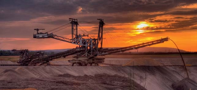
In the demanding world of surface mining operations, where equipment such as draglines, electric shovels, bucket-wheel excavators, and drilling rigs require continuous mobile power supply, these cables serve as the critical lifeline connecting stationary power sources to mobile machinery operating under extreme mechanical stress, abrasion, and environmental challenges.
2. Purpose and Applications
2.1 Primary Purpose
The (N)TSCGECEWÖU cable is specifically engineered for energy supply to heavy mobile mining equipment during trailing operations in opencast (surface) mining environments. These cables function as flexible power transmission links that must endure continuous movement, dragging across rough terrain, and exposure to harsh environmental conditions while maintaining electrical integrity and safety.
2.2 Target Equipment and Applications
These specialized cables are designed for powering:
- Draglines: Large excavating machines that use a suspended bucket to remove overburden and extract minerals
- Electric Shovels: Heavy-duty excavation equipment for loading materials into haul trucks
- Dredges: Equipment for underwater excavation and material removal
- Rotary Drills: Large drilling rigs for blast hole preparation and mineral exploration
- Bucket-Wheel Excavators: Continuous mining equipment with rotating bucket systems
- Mobile Crushers: Portable crushing equipment requiring flexible power connections
2.3 Operating Environment
These cables are specifically designed for:
- Opencast (surface) mining operations
- Extreme mechanical stress during trailing and dragging
- Continuous abrasion against rough surfaces and mineral materials
- Wide temperature variations (-25°C to +80°C during mobile operation)
- Exposure to oil, ozone, UV radiation, and weathering
- Both indoor and outdoor installation environments
3. Key Characteristics
3.1 Exceptional Flexibility
The cable features Class 5 conductor construction according to VDE 0295 (IEC 60228), providing maximum flexibility for continuous movement and coiling operations. The stranded tinned copper conductors are specifically designed to withstand millions of bending cycles without conductor breakage.
3.2 Superior Mechanical Strength
Maximum Tensile Load
15 N/mm²
Based on total phase conductor cross-section
Bending Radius
Per VDE 0298 Part 3
Optimized for reeling operations
Abrasion Resistance
5GM5 Quality
Dual-layer rubber compound protection
3.3 Advanced Electrical Design
- Voltage Range: 3.6/6 kV to 12/20 kV rated voltage
- Electrical Field Control: Triple-extruded semiconductive layers (inner and outer) provide uniform electrical field distribution
- Conductor Material: Tinned copper for enhanced corrosion resistance and electrical conductivity
- Earth Protection: Dedicated bare copper braid earth conductors for enhanced safety
- Current Rating: According to VDE 0298 Part 4 specifications
3.4 Thermal Performance
The cable’s thermal characteristics are optimized for continuous operation:
- Maximum continuous operating temperature: 90°C on conductor
- Short-circuit temperature tolerance: 250°C
- Mobile operation ambient range: -25°C to +80°C
- Static installation ambient range: -40°C to +80°C
3.5 Anti-Twisting Technology
A critical feature of the (N)TSCGECEWÖU design is the polyester braid anti-twisting element positioned between the inner and outer sheaths. This engineering solution prevents cable rotation and twisting during reeling and unreeling operations, significantly extending cable service life and preventing premature failure.
3.6 Environmental Resistance
- Flame Retardant: Complies with IEC 60332-1-2 for fire safety
- Oil Resistant: Tested per IEC 60811-2-1
- Ozone Resistant: Maintains integrity in high-ozone environments (IEC 60811-2-1)
- Weather Resistant: Suitable for continuous outdoor exposure
- UV Resistant: Rubber compounds resist degradation from solar radiation
4. Material Structure and Construction
The (N)TSCGECEWÖU cable features a sophisticated multi-layer construction designed to meet the demanding requirements of mining operations. Each layer serves a specific function in ensuring electrical performance, mechanical protection, and operational longevity.
4.1 Layer-by-Layer Construction
| Layer | Component | Material | Function |
|---|---|---|---|
| 1 | Phase Conductors | Tinned copper, Class 5 VDE 0295 | Power transmission with maximum flexibility |
| Conductor Shield | Semiconductive tape | Electrical field control at conductor interface | |
| Insulation | 3GI3 quality rubber compound (VDE 0207 Part 20) | Primary electrical insulation | |
| Insulation Shield | Inner and outer semiconductive rubber layers | Uniform electrical field distribution | |
| 2 | Protective Earth Conductors | Bare copper braid (3 conductors) | Safety grounding and fault protection |
| Central Filler | Rubber compound on textile polyester support | Cable roundness and mechanical stability | |
| Core Assembly | Twisted cores with semiconductive tape separator | Structural integrity and electrical separation | |
| 3 | Inner Sheath | 5GM5 quality abrasion-resistant rubber (VDE 0207 Part 21) | Primary mechanical protection and abrasion resistance |
| 4 | Anti-Twisting Element | Polyester braid | Prevents cable rotation during reeling operations |
| 5 | Outer Sheath | 5GM5 quality abrasion-resistant rubber (VDE 0207 Part 21) | Final environmental protection and abrasion resistance |
4.2 Material Specifications
4.2.1 Conductor Materials
Tinned Copper Conductors: The use of tinned (tin-coated) copper provides several advantages over bare copper:
- Enhanced corrosion resistance in humid mining environments
- Improved solderability for terminations
- Prevention of copper migration in high-temperature applications
- Extended service life in sulfur-containing atmospheres
4.2.2 Insulation System
3GI3 Quality Rubber Compound: This specialized insulation material conforms to VDE 0207 Part 20 and offers:
- Excellent dielectric properties for voltage ratings up to 12/20 kV
- Flexibility retention across wide temperature ranges
- Resistance to tracking and corona formation
- Long-term aging stability
4.2.3 Semiconductive Layers
The cable employs a triple-extrusion process where the conductor shield, insulation, and insulation shield are extruded simultaneously in a single pass. This technology ensures:
- Perfect interface bonding between layers
- Elimination of air gaps and contamination
- Uniform electrical field distribution
- Prevention of partial discharge and electrical treeing
4.2.4 Sheath Materials
5GM5 Quality Rubber Compound: Both inner and outer sheaths use this premium abrasion-resistant material (VDE 0207 Part 21), providing:
- Outstanding resistance to mechanical wear and abrasion
- Flexibility maintenance in extreme temperatures
- Oil, ozone, and UV resistance
- Excellent tear propagation resistance
5. Compliance with Standards
The (N)TSCGECEWÖU cable is manufactured and tested in accordance with multiple international and national standards, ensuring safety, reliability, and interoperability in global mining operations.
5.1 Primary Design Standard
DIN VDE 0250 Part 813: This is the fundamental German standard specifically addressing “Power cables with rubber insulation for rated voltages up to and including 18/30 kV – Part 813: Flexible cables for special installations.” This standard defines:
- Construction requirements for trailing cables
- Minimum insulation and sheath thickness (Table 2)
- Testing protocols for mechanical and electrical performance
- Safety requirements for mining applications
5.2 Conductor Standards
- VDE 0295 (equivalent to IEC 60228): Defines conductor classes and construction. Class 5 designation ensures maximum flexibility for flexible cables and cords.
5.3 Material Standards
- VDE 0207 Part 20: Specifications for 3GI3 quality rubber insulation compounds
- VDE 0207 Part 21: Specifications for 5GM5 quality abrasion-resistant rubber sheath compounds
5.4 Electrical Performance Standards
- VDE 0298 Part 4: Current-carrying capacity calculations for power cables
- VDE 0298 Part 3: Bending radius requirements for flexible installations
5.5 Testing Standards
| Property | Standard | Requirement |
|---|---|---|
| Flame Retardancy | IEC 60332-1-2 | Single vertical wire flame test |
| Oil Resistance | IEC 60811-2-1 | Resistance to mineral oil immersion |
| Ozone Resistance | IEC 60811-2-1 | No cracking after ozone exposure |
| High Voltage Test | IEC 60840 | AC voltage withstand test |
| Partial Discharge | IEC 60885-3 | PD testing for medium voltage cables |
5.6 Safety and Quality Certifications
Cables manufactured to these standards typically carry certifications from:
- VDE Testing and Certification Institute
- TÜV (Technischer Überwachungsverein) for product safety
- CE marking for European market compliance
- National mining authorities approvals where applicable
6. Safety Thresholds and Operating Limits
Understanding and adhering to the safety thresholds and operating limits is critical for preventing equipment damage, ensuring personnel safety, and maintaining optimal cable performance.
6.1 Electrical Safety Limits
| Parameter | 3.6/6 kV | 6/10 kV | 8.7/15 kV | 12/20 kV |
|---|---|---|---|---|
| Nominal Rated Voltage U₀/U | 3.6/6 kV | 6/10 kV | 8.7/15 kV | 12/20 kV |
| Test Voltage (AC) | 11 kV | 17 kV | 24 kV | 29 kV |
| Maximum AC Voltage | 4.2/7.2 kV | 6.9/12 kV | 10.4/18 kV | 13.9/24 kV |
Critical Safety Note: The cable must NEVER be operated above the maximum AC voltage specified for each rating. Operating above these limits can lead to insulation breakdown, electrical arcing, and severe safety hazards.
6.2 Thermal Operating Limits
Normal Operating Temperature
Maximum 90°C
Continuous operation on conductor
Short Circuit Temperature
Maximum 250°C
Brief duration (typically 5 seconds)
Ambient Temperature (Mobile)
-25°C to +80°C
During trailing operations
Ambient Temperature (Static)
-40°C to +80°C
For fixed installations
⚠️ Thermal Overload Warning
Exceeding the 90°C continuous operating temperature can result in:
- Accelerated insulation aging and reduced service life
- Softening of rubber compounds leading to mechanical failure
- Increased risk of electrical breakdown
- Potential fire hazards
Recommendation: Install temperature monitoring systems on high-power cables and implement automatic shutdown protocols when temperature thresholds are approached.
6.3 Mechanical Loading Limits
6.3.1 Tensile Stress Limits
Maximum Tensile Load: 15 N/mm² (referred to total phase conductor cross-section)
Example calculation for a 3×95 mm² + 3×50/3E cable:
- Total phase conductor area: 3 × 95 mm² = 285 mm²
- Maximum permissible tensile force: 285 mm² × 15 N/mm² = 4,275 N
- Safety factor consideration: Recommended working load should not exceed 50-60% of maximum (2,100-2,500 N)
6.3.2 Bending Radius Requirements
According to VDE 0298 Part 3, minimum bending radius during installation and operation must be maintained to prevent conductor damage and insulation stress. Typical requirements:
- Installation bending radius: Generally 15-20 times the cable outer diameter
- Operating bending radius: May be reduced but should never be less than 12 times outer diameter
- Reeling drum diameter: Minimum 20-25 times cable outer diameter
6.4 Current Carrying Capacity
Current ratings must be determined according to VDE 0298 Part 4, considering:
- Conductor cross-section
- Installation method (buried, in air, trailing)
- Ambient temperature
- Grouping factors (multiple cables)
- Load cycle (continuous or intermittent)
Derating Factors: For trailing cables in mining applications, additional derating may be required due to:
- High ambient temperatures in certain mining environments
- Accumulation of dust and debris reducing heat dissipation
- Coiling of excess cable on reels (reduced cooling)
7. Precautions for Use
7.1 Installation Precautions
7.1.1 Storage and Handling
- Storage Conditions: Store cable reels in dry, covered areas protected from direct sunlight and extreme temperatures
- Temperature Conditioning: Before installation in cold weather, allow cables to warm to at least 0°C to prevent rubber cracking
- Reel Handling: Use appropriate lifting equipment; never drop or roll cable reels
- Cable Pulling: Avoid dragging cable over sharp edges or rough surfaces during installation
- Tension Control: Monitor pulling tension to ensure it does not exceed 50% of maximum tensile load
7.1.2 Termination and Connection
- Use only manufacturer-approved cable termination kits and connectors
- Ensure proper preparation of semiconductive layers and field control stress cones
- Maintain cleanliness during termination to prevent contamination
- Apply correct torque values to all mechanical connections
- Verify earth continuity before energization
- Perform high-voltage testing after termination (per manufacturer specifications)
7.1.3 Reeling System Design
- Drum Diameter: Minimum 20-25 times cable outer diameter
- Fleet Angle: Keep within ±3° to prevent cable damage
- Level Winding: Install level wind mechanisms to ensure uniform cable coiling
- Tension Control: Implement constant tension systems during reeling and unreeling
- Limit Switches: Install travel limits to prevent over-travel and cable damage
7.2 Operational Precautions
7.2.1 Load Management
- Never exceed the rated current capacity of the cable
- Implement overcurrent protection devices properly coordinated with cable ratings
- Consider load diversity and duty cycles in capacity calculations
- Monitor voltage drop to ensure equipment receives adequate voltage
7.2.2 Environmental Monitoring
- Implement temperature monitoring for high-capacity applications
- Regularly inspect cable routes for accumulation of debris or obstructions
- Ensure adequate drainage to prevent cable submersion in water or slurry
- Remove sharp objects or debris from cable trailing paths
7.2.3 Emergency Procedures
- Establish clear lockout/tagout procedures for cable maintenance
- Train personnel on emergency shutdown procedures
- Maintain emergency spares and repair kits on-site
- Document all cable incidents and near-misses
7.3 Maintenance Precautions
7.3.1 Regular Inspection Schedule
| Frequency | Inspection Items | Action Required |
|---|---|---|
| Daily | Visual inspection for cuts, abrasion, overheating | Immediate repair or replacement if damage found |
| Weekly | Termination tightness, earth continuity, reeling system function | Retorque connections, verify earth integrity |
| Monthly | Insulation resistance testing, detailed visual inspection | Document trends, plan preventive maintenance |
| Quarterly | Comprehensive electrical testing, mechanical measurements | Compare with baseline data, assess remaining life |
| Annually | Complete electrical testing including high-voltage tests | Professional assessment, consider replacement if degraded |
7.3.2 Testing Precautions
- Insulation Resistance: Test at recommended DC voltage (typically 5-10 kV for these cables)
- High-Voltage Testing: Only perform with proper equipment and qualified personnel
- Continuity Testing: Verify all conductors and earth connections
- Partial Discharge Testing: Consider for cables in critical applications
⚠️ Critical Safety Warning
De-energization Required: All inspection, testing, and maintenance activities must be performed with the cable completely de-energized, isolated, and verified as having no voltage present. Follow proper lockout/tagout procedures.
Qualified Personnel Only: Work on medium-voltage cables must only be performed by qualified electricians trained in high-voltage safety procedures.
7.4 Disposal and Environmental Precautions
- Follow local regulations for disposal of electrical cables
- Recover and recycle copper and other valuable materials where possible
- Dispose of rubber compounds through certified waste handlers
- Maintain records of cable disposal for environmental compliance
8. Common Problems and Solutions
8.1 Mechanical Damage Issues
Problem 1: Outer Sheath Abrasion and Cuts
Symptoms:
- Visible wear on outer sheath surface
- Exposure of inner sheath or anti-twist braid
- Localized damage at specific points along cable length
Causes:
- Excessive dragging over sharp or rough surfaces
- Improper trailing path with obstacles
- Insufficient sheath thickness for application
- Chemical attack from spilled materials
Solutions:
- Improve trailing path by removing sharp objects and obstacles
- Install protective cable guides or chutes at critical points
- Consider using cable with thicker sheath or additional protection
- Implement more frequent inspection and rotation schedules
- Apply temporary protective wrapping at high-wear areas
Problem 2: Cable Twisting and Kinking
Symptoms:
- Cable develops permanent spiral or twist
- Difficulty in smooth reeling and unreeling
- Localized kinks or bends in cable
- Premature conductor failure
Causes:
- Failure or absence of anti-twisting element
- Improper reeling system design (excessive fleet angle)
- Lack of proper level-winding mechanism
- Incorrect drum rotation direction
Solutions:
- Verify integrity of anti-twist polyester braid
- Redesign reeling system to maintain proper fleet angle
- Install or repair level-wind mechanisms
- Implement swivel connections where appropriate
- Replace cable if permanent deformation has occurred
8.2 Electrical Failure Issues
Problem 3: Insulation Breakdown
Symptoms:
- Ground fault alarms or trips
- Visible tracking or carbonization on cable surface
- Low insulation resistance readings
- Electrical noise or partial discharge detection
Causes:
- Moisture ingress through damaged sheath
- Thermal overload causing insulation degradation
- Mechanical damage to insulation from excessive bending
- Aging and weathering of insulation materials
- Electrical stress concentration at terminations
Solutions:
- Perform insulation resistance testing to locate fault zone
- Replace damaged cable section or entire cable if extensive
- Improve moisture sealing at terminations and splices
- Review load profiles to prevent thermal overload
- Implement preventive replacement based on insulation testing trends
Problem 4: Conductor Breakage
Symptoms:
- Complete loss of power to equipment
- Phase imbalance or single-phasing conditions
- Intermittent connection (open-circuit under tension)
Causes:
- Fatigue failure from excessive bending cycles
- Mechanical overload exceeding tensile limits
- Corrosion of copper conductors
- Poor quality conductor stranding
- Localized heating and annealing of conductor
Solutions:
- Replace cable with appropriate conductor class for application
- Review and correct reeling system to reduce bending stress
- Implement tension monitoring and control systems
- Ensure proper sizing to prevent thermal overload
- Consider tinned copper alternatives if corrosion is issue
8.3 Termination and Connection Issues
Problem 5: Termination Failures
Symptoms:
- Localized heating at termination points
- Partial discharge or corona at termination
- Flashover between phases or to ground
- Loose connections causing arcing
Causes:
- Improper stress cone installation
- Contamination during termination process
- Inadequate creepage distances
- Loose mechanical connections
- Use of incorrect termination kits
Solutions:
- Re-terminate using manufacturer-approved kits and procedures
- Ensure clean working environment during termination
- Verify proper dimensions and torque specifications
- Perform high-voltage testing after termination
- Implement periodic thermographic inspection of terminations
8.4 Environmental Degradation Issues
Problem 6: Weather and UV Deterioration
Symptoms:
- Surface cracking or chalking of outer sheath
- Hardening and loss of flexibility
- Discoloration of rubber compounds
Causes:
- Prolonged exposure to UV radiation
- Extreme temperature cycling
- Ozone exposure in industrial environments
Solutions:
- The 5GM5 rubber compound provides good resistance, but protection can be enhanced
- Minimize exposed cable length when not in use
- Store cable indoors when equipment is idle for extended periods
- Consider UV-protective cable covers for critical exposed sections
- Plan replacement based on visible degradation before safety is compromised
8.5 Operational and System Issues
Problem 7: Excessive Voltage Drop
Symptoms:
- Equipment underperformance or malfunction
- Motor overheating or failure to start
- Frequent overcurrent trips
Causes:
- Cable undersized for actual load and length
- Poor connections increasing resistance
- Excessive cable length in trailing configuration
Solutions:
- Calculate actual voltage drop considering all factors
- Upgrade to larger conductor cross-section if needed
- Improve connection quality at all joints
- Minimize cable length through optimized layout
- Consider voltage compensation at equipment end
9. Technical Specifications
9.1 Complete Electrical Parameters
| Parameter | 3.6/6 kV | 6/10 kV | 8.7/15 kV | 12/20 kV |
|---|---|---|---|---|
| Nominal Rated Voltage U₀/U | 3.6/6 kV | 6/10 kV | 8.7/15 kV | 12/20 kV |
| Test Voltage (AC, 5 min) | 11 kV | 17 kV | 24 kV | 29 kV |
| Maximum AC Voltage | 4.2/7.2 kV | 6.9/12 kV | 10.4/18 kV | 13.9/24 kV |
| Current Rating | According to VDE 0298 Part 4 (varies with conductor size) | |||
9.2 Thermal Characteristics
| Parameter | Value | Notes |
|---|---|---|
| Maximum Conductor Temperature (Continuous) | 90°C | Normal operating condition |
| Maximum Short Circuit Temperature | 250°C | Maximum 5 seconds duration |
| Ambient Temperature (Mobile Operation) | -25°C to +80°C | During trailing/reeling operations |
| Ambient Temperature (Static Installation) | -40°C to +80°C | Fixed installation conditions |
9.3 Mechanical Properties
| Property | Specification | Standard Reference |
|---|---|---|
| Conductor Construction | Class 5 (flexible) | VDE 0295 / IEC 60228 |
| Maximum Tensile Load | 15 N/mm² | Based on total phase conductor area |
| Minimum Bending Radius | Per VDE 0298 Part 3 | Typically 15-20× cable OD |
9.4 Available Cable Configurations (3.6/6 kV)
| Conductor Size (mm²) | Construction | Min Overall Ø (mm) | Max Overall Ø (mm) | Approx. Weight (kg/km) | Max Tensile Load (N) |
|---|---|---|---|---|---|
| 3×25 + 3×25/3E | 3×25 mm² + 3 earth | 6.8 | 43.4 – 45.1 | 2,850 | 1,125 |
| 3×35 + 3×25/3E | 3×35 mm² + 3 earth | 7.8 | 45.0 – 46.7 | 3,200 | 1,575 |
| 3×50 + 3×25/3E | 3×50 mm² + 3 earth | 9.4 | 48.1 – 49.8 | 3,850 | 2,250 |
| 3×70 + 3×35/3E | 3×70 mm² + 3 earth | 11.2 | 53.7 – 55.5 | 4,980 | 3,150 |
| 3×95 + 3×50/3E | 3×95 mm² + 3 earth | 12.7 | 58.4 – 60.2 | 6,200 | 4,275 |
| 3×120 + 3×70/3E | 3×120 mm² + 3 earth | 14.4 | 62.9 – 65.2 | 7,580 | 5,400 |
| 3×150 + 3×70/3E | 3×150 mm² + 3 earth | 16.3 | 69.3 – 71.7 | 9,090 | 6,750 |
Note: Similar configurations are available for 6/10 kV, 8.7/15 kV, and 12/20 kV ratings with proportionally increased overall diameters and weights. Complete specifications available upon request.
9.5 Chemical and Environmental Resistance
| Property | Standard | Performance |
|---|---|---|
| Flame Retardancy | IEC 60332-1-2 | Passes single vertical wire test |
| Oil Resistance | IEC 60811-2-1 | Resistant to mineral oils and lubricants |
| Ozone Resistance | IEC 60811-2-1 | No cracking after specified exposure |
| Weather Resistance | — | Suitable for indoor and outdoor use |
| UV Resistance | — | Rubber compounds resist solar degradation |
Conclusion
The (N)TSCGECEWÖU round reeling cable represents the pinnacle of engineering for extreme-duty mining applications. Designed and manufactured according to rigorous DIN VDE 0250 Part 813 standards, these cables provide reliable, safe power transmission to heavy mobile mining equipment operating under the most challenging conditions.
Key takeaways include:
- Sophisticated multi-layer construction with specialized materials optimized for flexibility, abrasion resistance, and electrical performance
- Comprehensive compliance with international standards (VDE, IEC, DIN) ensuring safety and reliability
- Well-defined operating limits and safety thresholds that must be strictly observed
- Importance of proper installation, maintenance, and inspection procedures
- Understanding common failure modes and their prevention
Success with these cables requires a holistic approach combining proper specification, expert installation, diligent maintenance, and ongoing monitoring. When these principles are followed, (N)TSCGECEWÖU cables deliver exceptional performance and longevity in the demanding mining environment.
Contact Anhui Feichun Special Cable Co., Ltd.
For technical specifications, quotations, or expert consultation on mining cable solutions:
Anhui Feichun Special Cable Co., Ltd. (安徽飞纯特种电缆有限公司) – Your trusted partner for specialized mining cable solutions.


