
High-Visibility Yellow Three-Core MV Cable with Special Abrasion-Resistant Sheath for Draglines, Shovels, Dredges & Drills Based on DIN VDE 0250 Part 813
What is (N)TSCGEWÖU Mining Cable for Heavy Equipment?
High-Visibility Yellow Three-Core MV Cable with Special Abrasion-Resistant Sheath for Draglines, Shovels, Dredges & Drills Based on DIN VDE 0250 Part 813
⚡ CRITICAL SAFETY WARNING – MEDIUM VOLTAGE IN MINING ENVIRONMENTS
This cable operates at medium voltage levels (3,600V to 20,000V) in hazardous mining environments – IMMEDIATELY LETHAL. Installation, testing, maintenance, and repair must be performed ONLY by certified high-voltage electrical personnel with mining electrical certification, following all applicable mining safety regulations, lockout/tagout procedures, and using appropriate high-voltage safety equipment. Mining operations present additional hazards including explosive atmospheres, mobile equipment, and confined spaces.
(N)TSCGEWÖU Mining Cables represent a specialized variant of three-core medium voltage flexible cables specifically engineered for the most demanding opencast mining applications. This cable combines proven (N)TSCGEWÖU electrical and mechanical performance with a special abrasion-resistant yellow outer sheath designed for heavy mobile mining equipment including draglines, power shovels, dredges, and drills operating under extreme mechanical stresses and continuous abrasion during trailing operations.
The distinctive high-visibility yellow color is mandatory in many mining operations for safety identification, allowing equipment operators and ground personnel to easily locate and avoid the power cable. Combined with enhanced abrasion resistance, this cable is purpose-built for the harsh realities of opencast mining where cables are dragged across rough terrain, exposed to coal dust, rocks, and continuous mechanical punishment.
1. Cable Overview and Mining Applications
Purpose-Built for Opencast Mining Operations
This specialized (N)TSCGEWÖU variant is engineered specifically for the unique challenges of opencast (open-pit/surface) mining operations where cables must withstand:
- Continuous Trailing: Cable drags behind moving equipment across rough, abrasive terrain
- Extreme Abrasion: Constant contact with rocks, coal, ore, and abrasive minerals
- Heavy Equipment Loads: Multi-megawatt power requirements for draglines and large shovels
- Harsh Environmental Conditions: Dust, moisture, temperature extremes, and weather exposure
- Safety-Critical Visibility: High-visibility yellow for equipment operator awareness
- 24/7 Operation: Continuous duty cycles in around-the-clock mining operations
🟡 Why Yellow High-Visibility Color?
The bright yellow outer sheath serves critical safety functions in mining operations:
- Equipment Operator Awareness: Highly visible to operators of excavators, trucks, and other mobile equipment
- Ground Personnel Safety: Workers can easily identify and maintain safe distances from energized cables
- Emergency Response: First responders can quickly locate cable routes during incidents
- Regulatory Compliance: Many mining jurisdictions mandate high-visibility colors for MV trailing cables
- Maintenance Identification: Easy to distinguish from other cables during inspection and repair
- Day and Night Visibility: Yellow provides high contrast in both daylight and artificial lighting conditions
Primary Mining Equipment Applications
Draglines
Large walking dragline excavators (100+ tons bucket capacity) requiring multi-megawatt power for hoist, drag, and walking mechanisms.
Electric Shovels
Power shovels and mining shovels with electric drives requiring reliable MV power for digging, swinging, and propel operations.
Dredges
Bucket-wheel and cutter-head dredges used in mining and excavation requiring power for cutting mechanisms and material transport.
Large Drills
Rotary blast-hole drills and other large drilling equipment requiring high power for drilling operations in hard rock formations.
Mobile Crushers
Portable crushing and screening equipment requiring MV power for crushing mechanisms and conveyor systems.
Bucket-Wheel Excavators
Continuous mining machines with large bucket wheels requiring power for excavation, conveying, and slewing operations.
2. Key Characteristics for Mining Equipment
Enhanced Abrasion Resistance
Special Abrasion-Resistant Outer Sheath
The 5GM5 quality rubber compound used for the outer sheath in this mining variant features enhanced abrasion resistance compared to standard formulations:
- Hardness Optimization: Balanced hardness prevents cutting while maintaining flexibility
- Tear Resistance: Reinforced polymer matrix resists tearing from sharp rocks and debris
- Cut Resistance: Special compounds resist cutting from sharp edges during trailing
- Wear Life: Extended service life in continuous abrasion conditions (3-5x standard cables)
- Self-Healing Properties: Minor surface damage does not propagate through sheath thickness
- Chunking Resistance: Resists chunk-out damage common with softer rubber compounds
Trailing Cable Performance
Unlike reeling cables that wind onto drums, trailing cables drag behind equipment on the ground, creating unique demands:
| Trailing Cable Challenge | Design Response |
|---|---|
| Ground Abrasion | Special abrasion-resistant outer sheath with high wear resistance |
| Rock Impact | Enhanced sheath thickness and impact-resistant compound |
| Pulling/Dragging Forces | 20 N/mm² tensile strength (higher than standard cables) |
| Multi-Directional Flexing | ±25°/m torsional stress capability and twisted core design |
| Coal Dust/Moisture | Weather-resistant outer sheath with complete environmental sealing |
| High Visibility Required | Bright yellow color for safety identification |
| Continuous Duty | 90°C continuous conductor temperature, designed for 24/7 operation |
Electrical Performance for Heavy Equipment
- Voltage Ratings: 3.6/6 kV, 6/10 kV, 8.7/15 kV, 12/20 kV
- Three-Phase Power: Complete three-phase power in single cable assembly
- High Current Capacity: Conductor sizes from 25mm² to 185mm² per phase
- Power Levels: Supports multi-megawatt equipment (draglines often 5-10+ MW)
- Earth Conductor System: Three-part split earth conductors for reliable fault protection
Mechanical Performance Specifications
- Torsional Stress: ±25°/m – handles cable twisting during equipment movement
- Tensile Load: 20 N/mm² – withstands pulling forces during trailing operation
- Bending Radius: Per VDE 0298-3 (optimized for mobile equipment)
- Temperature Range (Mobile): -25°C to +80°C – suitable for most mining climates
- Temperature Range (Static): -40°C to +80°C – extended range for stationary portions
Environmental Protection Features
Mining Environment Protection
- Weather Resistance: UV-stable yellow sheath for outdoor exposure
- Water/Moisture Resistance: Complete sealing against rain, snow, and groundwater
- Oil Resistance: Per IEC 60811-2-1 – resists hydraulic fluids and lubricants
- Ozone Resistance: Per IEC 60811-2-1 – prevents cracking from ozone exposure
- Dust Resistance: Sealed construction prevents coal/ore dust ingress
- Chemical Resistance: Resists common mining chemicals and solvents
- Flame Retardancy: Per IEC 60332-1-2 – critical for underground/confined spaces
3. Construction with Enhanced Abrasion Protection
The mining-specific (N)TSCGEWÖU features ten-layer construction optimized for trailing operations:
Layer 1: Phase Conductors (3 cores)
Material: Tinned copper
Construction: Class 5 VDE 0295 (IEC 60228) with special enhanced flexibility
Sizes: 25mm² to 185mm² per phase (larger sizes available)
Function: Delivers three-phase power to mining equipment while maintaining flexibility for trailing operation.
Layer 2-4: Insulation System (each phase)
Conductor Screen: Semiconductive tape over each conductor
Primary Insulation: 3GI3 quality rubber compound per VDE 0207 Part 20
Semiconductive Layers: Inner and outer semiconductive rubber layers co-extruded with insulation
Function: Complete electrical field control system for each phase conductor.
Layer 5: Earth Conductors (3 separate conductors)
Material: Tinned copper, Class 5 flexible
Configuration: Split into 3 parts distributed around phase cores
Covering: Semiconductive layer on each earth conductor
Function: Redundant grounding system critical for mining safety, provides multiple fault current paths and electromagnetic shielding.
Layer 6: Central Filler
Material: Semiconductive compound on textile polyester support
Function: Maintains circular cable cross-section and provides internal mechanical support during flexing and twisting.
Layer 7: Cores Assembly
Assembly: Twisted cores with earth conductors integrated
Separator: Semiconductive tape wound over twisted assembly
Function: Twisted construction distributes mechanical stress and prevents individual core deformation during cable movement.
Layer 8: Inner Sheath (Gm1b/5GM5 Quality)
Material: Gm1b/5GM5 quality rubber compound per VDE 0207 Part 21
Thickness: Per VDE 0250 Part 813 Table 2
Function: Primary mechanical protection for core assembly and foundation for anti-twisting element.
Layer 9: Anti-Twisting Element
Material: Polyester braid between inner and outer sheaths
Function: Provides ±25°/m torsional stress resistance essential for trailing cables that twist as equipment moves and rotates.
Layer 10: Special Abrasion-Resistant Yellow Outer Sheath
Material: Special abrasion-resistant rubber compound 5GM5 quality per VDE 0207 Part 21
Thickness: Per VDE 0250 Part 813 Table 2 (increased thickness for enhanced protection)
Color: HIGH-VISIBILITY YELLOW
Special Features:
- Enhanced abrasion resistance for continuous ground contact
- High tear and cut resistance from reinforced polymer formulation
- UV-stable yellow pigmentation maintaining visibility over cable life
- Weather-resistant for all outdoor conditions
- Flame retardant per IEC 60332-1-2
- Self-healing properties preventing minor damage propagation
Function: Critical outer protection layer designed specifically for the abrasive conditions of opencast mining trailing operations. The yellow color provides essential high-visibility safety identification.
Sheath Thickness and Protection
The special abrasion-resistant outer sheath is significantly thicker than standard industrial cables:
- Standard industrial cable sheath: 2.0-3.0mm typical
- Mining trailing cable sheath: 3.5-5.0mm or greater (size-dependent)
- Provides approximately 2-3x the abrasion protection thickness
- Extended service life in trailing applications: 5-10+ years depending on conditions
4. Heavy Mobile Mining Equipment Applications
1. Dragline Excavators
World’s Largest Mobile Mining Equipment
Draglines are among the largest mobile machines on Earth, used primarily in opencast coal mining:
- Typical Power Requirements: 5-15 MW (some exceed 20 MW)
- Operating Voltage: Typically 6/10 kV or 12/20 kV systems
- Bucket Capacity: 30-220 cubic meters (up to 300+ tons)
- Walking Mechanism: “Walking” draglines require continuous power during movement
- Cable Length: Often 300-1000+ meters from substation to dragline
- Trailing Conditions: Cable drags continuously behind walking dragline across rough overburden
Cable Requirements for Draglines:
- Very large conductor sizes (120mm², 150mm², 185mm² per phase) for high power
- Extreme abrasion resistance from continuous ground contact
- High flexibility for cable to follow dragline movement patterns
- Yellow high-visibility color mandatory for safety
- 24/7 operation capability with minimal maintenance downtime
2. Electric Power Shovels
Large electric shovels used for overburden removal and ore loading:
- Power Range: 2-10 MW depending on shovel size
- Bucket Capacity: 15-80 cubic meters typical
- Operations: Digging, swinging, dumping, and propel all powered electrically
- Mobility: Crawlers or walking shoes with cable trailing behind
- Duty Cycle: Repetitive cycles create continuous cable flexing
- Environment: Heavy dust, falling rocks, and extreme mechanical stress
3. Dredges for Mining Operations
- Bucket-Wheel Dredges: Continuous excavation with rotating bucket wheel
- Cutter-Head Dredges: Rotating cutter head for hard materials
- Power Requirements: 1-8 MW depending on size and material
- Applications: Sand/gravel mining, phosphate mining, offshore diamond mining
- Cable Configuration: Often requires water-resistant construction in addition to standard features
4. Large Blast-Hole Drills
Rotary drills for creating blast holes in hard rock mining:
- Power Range: 500 kW – 3 MW
- Drill Hole Diameter: 200-450mm typical
- Drilling Depth: 15-50+ meters per hole
- Mobility: Track-mounted or crawler-mounted with trailing cable
- Conditions: Rock dust, vibration, and continuous movement between drill holes
- Cable Challenges: Frequent repositioning creates continuous cable movement and flexing
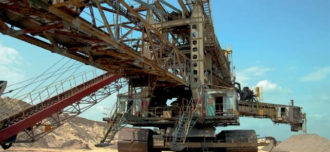
5. Bucket-Wheel Excavators
Continuous mining machines for soft to medium-hard materials:
- Power Requirements: 3-12 MW depending on machine size
- Bucket Wheel Diameter: 10-20+ meters
- Excavation Capacity: Up to 12,000 cubic meters per hour
- Applications: Brown coal (lignite) mining, soft ore excavation
- Cable Configuration: Very long cable runs (500-1500m common) with special cable management systems
Cable Selection Guidelines by Equipment Type
| Equipment Type | Typical Voltage | Typical Conductor Size | Key Cable Requirements |
|---|---|---|---|
| Large Draglines (>100m³ bucket) | 12/20 kV | 150-185 mm² | Maximum abrasion resistance, very long lengths |
| Medium Draglines (30-100m³) | 6/10 kV | 95-150 mm² | High abrasion resistance, moderate flexibility |
| Electric Shovels | 6/10 kV or 8.7/15 kV | 70-120 mm² | Abrasion + flexibility, frequent repositioning |
| Large Drills | 3.6/6 kV or 6/10 kV | 35-70 mm² | Flexibility for frequent moves, dust resistance |
| Bucket-Wheel Excavators | 6/10 kV or 12/20 kV | 95-185 mm² | Very long lengths, cable management systems |
| Mobile Crushers | 3.6/6 kV | 50-95 mm² | Abrasion resistance, moderate power |
5. Compliance with Mining Standards
Mining-specific (N)TSCGEWÖU cables must comply with electrical cable standards PLUS mining industry regulations:
Electrical Cable Standards
Mining Industry Regulations
Additional requirements for mining applications vary by country/region:
United States – MSHA Requirements
- MSHA 30 CFR Part 75: Underground coal mine electrical requirements
- MSHA 30 CFR Part 56/57: Surface and underground metal/nonmetal mine safety
- Flame Resistance: Specific testing requirements for mining cables
- Color Coding: High-visibility colors required for trailing cables
Australia – Mining Safety Standards
- AS/NZS 1802: Electrical installations in mines
- AS 2380.3: Elastomer insulated cables for mines
- State Regulations: Queensland, NSW, WA specific mining electrical codes
South Africa – DMR Regulations
- SANS 1019: Winding engine equipment and performance
- DMR Regulations: Department of Mineral Resources electrical standards
- SABS Standards: South African Bureau of Standards cable requirements
European Union – Mining Directives
- ATEX Directive: Equipment for explosive atmospheres (when applicable)
- Machinery Directive: Essential health and safety requirements
- National Regulations: Germany (BGR), UK (HSE), Poland mining codes
Yellow Color Specification and Testing
High-Visibility Yellow Requirements
The yellow outer sheath must meet specific visibility and durability standards:
- Color Specification: RAL 1023 (Traffic Yellow) or equivalent high-visibility yellow
- UV Stability: Color must not fade significantly over cable service life
- Accelerated Weathering: Testing to verify color retention after UV exposure
- Contrast Ratio: Must provide adequate contrast against typical mine backgrounds
- Night Visibility: Color should reflect light for visibility in artificial lighting
- Pigment Quality: Colorfast pigments that don’t leach or wash out
Special Testing for Mining Cables
- Abrasion Testing: Simulates ground dragging with standardized abrasive materials
- Impact Testing: Verifies sheath integrity after rock impact
- Tear Resistance: Testing for resistance to tearing from sharp objects
- Reeling Test: Verifies mechanical and electrical performance after cycling
- Environmental Testing: Temperature cycling, moisture, dust exposure
- Flame Testing: Enhanced requirements for mining applications
6. Safety Thresholds and Mining Requirements
⚡ MINING ELECTRICAL SAFETY – MULTIPLE HAZARDS
Mining operations present unique electrical hazards:
- Lethal Voltages: Medium voltage is immediately fatal on contact
- Mobile Equipment: Risk of cable damage from heavy equipment
- Explosive Atmospheres: Some mining areas may have flammable gas/dust
- Ground Faults: Wet conditions increase electrocution risk
- Arc Flash: High-power systems create severe arc flash hazards
- Confined Spaces: Limited escape routes in underground/pit operations
Only personnel with BOTH high-voltage electrical certification AND mining electrical certification may work on these cables.
Electrical Safety Parameters
| Voltage Rating U₀/U | Test Voltage (AC) | Max AC Operating Voltage | Common Mining Systems |
|---|---|---|---|
| 3.6/6 kV | 11 kV | 4.2/7.2 kV | Small drills, mobile crushers |
| 6/10 kV | 17 kV | 6.9/12 kV | Medium shovels, draglines, drills |
| 8.7/15 kV | 24 kV | 10.4/18 kV | Large shovels, bucket-wheels |
| 12/20 kV | 29 kV | 13.9/24 kV | Large draglines, major equipment |
Mining-Specific Safety Requirements
- Ground Fault Protection: Mandatory sensitive earth leakage protection systems
- Cable Monitoring: Pilot wire systems or cable integrity monitoring
- Emergency Stops: Accessible e-stop systems on all equipment
- Lockout/Tagout: Strict LOTO procedures for all electrical work
- Arc Flash PPE: Appropriate arc-rated clothing and face protection
- Rescue Equipment: Hot stick tools, insulated rescue equipment on-site
- Communication: Reliable communication systems for electrical work areas
Yellow Cable Visibility and Safety Distances
Safe Approach Distances for Equipment Operators
High-visibility yellow color enables operators to maintain safe distances:
- 6 kV systems: Minimum 3-meter clearance for mobile equipment
- 12 kV systems: Minimum 4-meter clearance recommended
- 20 kV systems: Minimum 5-meter clearance required
- Emergency Situations: Assume all yellow cables are energized
- Training: All equipment operators trained in cable identification and avoidance
Current Rating and Thermal Considerations
Current capacity in mining trailing applications requires special consideration:
- Ground Contact: Cable lying on ground has better cooling than in air
- Burial Effects: Portions buried in spoil/overburden have reduced capacity
- Ambient Temperature: Mining pit temperatures can be extreme (hot deserts, arctic)
- Solar Loading: Direct sunlight increases cable temperature
- Grouping: Multiple cables in proximity reduce individual capacity
- Duty Cycle: Continuous vs. intermittent operation affects thermal design
7. Installation and Usage in Mining Operations
⚠️ MINING-CERTIFIED PERSONNEL ONLY
Installation and maintenance requires:
- High-voltage electrical certification (jurisdiction-specific)
- Mining electrical safety certification
- Site-specific safety training and authorization
- Awareness of mobile equipment hazards
- Emergency response training
Installation Guidelines for Trailing Cables
1. Cable Route Planning
- Minimize Ground Contact: Use cable management systems where practical
- Avoid Sharp Corners: Gradual curves prevent excessive bending stress
- Clear Obstacles: Remove sharp rocks and debris from cable path
- Drainage Considerations: Route cables away from water accumulation areas
- Equipment Clearance: Ensure adequate clearance from haul roads and equipment paths
- Future Operations: Plan for pit expansion and equipment repositioning
2. Cable Handling During Installation
Heavy Cable Handling
Large mining cables are extremely heavy and require proper equipment:
- 3x95mm² cable: ~5,800 kg/km (nearly 6 tons per kilometer!)
- 3x185mm² cable: ~10,000 kg/km (10 tons per kilometer)
- Use cable drums, tractors, or winches for handling
- Never allow cable to be crushed or kinked during handling
- Multiple personnel required for safe handling operations
- Proper rigging and lifting equipment mandatory
3. Termination Requirements
- Use heavy-duty MV termination kits rated for mining conditions
- Terminations often located in mobile switchgear/substations
- Enhanced environmental sealing for dusty conditions
- Proper strain relief essential due to cable weight and pulling forces
- Regular inspection and maintenance of terminations
- Color-code and label all terminations clearly
4. Cable Support and Management Systems
- Cable Reelers: Motor-driven reeling systems for automatic cable retrieval
- Cable Handlers: Mechanical systems that lift cable off ground to reduce abrasion
- Saddles and Guides: Support structures at regular intervals
- Festoon Systems: For some applications, enclosed festoon systems can be used
- Slack Management: Maintain appropriate cable slack for equipment movement
Operational Precautions
1. Equipment Operator Responsibilities
Yellow Cable Awareness Training
All mobile equipment operators must be trained to:
- Recognize yellow high-visibility cables as energized MV power
- Maintain safe clearance distances at all times
- Report any visible cable damage immediately
- Follow designated equipment movement paths
- Never allow equipment to contact or run over cables
- Stop operations immediately if cable contact occurs
2. Load Management
- Verify cable ampacity for specific equipment load
- Monitor equipment power consumption to ensure it remains within cable ratings
- Account for derating factors (temperature, grouping, burial)
- Implement motor soft-start systems to reduce inrush currents
- Balance loads across three phases when possible
3. Environmental Protection
- Regularly inspect yellow sheath for cuts, abrasion, or damage
- Remove sharp rocks and debris from cable path
- Provide additional protection in high-traffic areas
- Prevent cable from being buried in spoil piles
- Ensure proper drainage to prevent standing water contact
Maintenance and Inspection
Mining Cable Inspection Schedule
- Pre-Shift Inspection: Visual walk-down of cable route (daily)
- Weekly Detailed Inspection: Thorough examination of sheath condition
- Monthly Testing: Ground fault protection system testing
- Quarterly Assessment: Insulation resistance testing (during equipment downtime)
- Annual Major Inspection: Complete electrical testing and mechanical assessment
Critical Inspection Points
- Sheath Integrity: Check yellow sheath for cuts, tears, or severe abrasion
- High-Wear Areas: Pay special attention to areas with heavy ground contact
- Terminations: Inspect for tracking, overheating, moisture ingress
- Cable Route: Verify no new obstacles or hazards have appeared
- Support Systems: Check cable reelers, handlers, and support structures
- Color Retention: Verify yellow color remains highly visible
8. Common Mining-Specific Problems and Solutions
1. Excessive Sheath Abrasion/Wear
Symptoms: Yellow outer sheath worn through, exposing inner layers; cable appears flattened or damaged in contact areas.
Causes:
- Dragging over rough, abrasive terrain (rock, coal, ore)
- Insufficient cable management systems
- Cable route over particularly abrasive materials
- Excessive cable length causing more ground contact
- Improper cable for application (insufficient abrasion resistance)
Solutions:
- Implement cable handler/reeler system to reduce ground contact
- Clear sharp rocks and debris from cable route
- Rotate cable periodically to distribute wear
- Install cable saddles at high-wear points
- Replace cable section if inner sheath is exposed
- Consider upgrading to thicker-sheathed variant if available
2. Cable Damage from Mobile Equipment
Symptoms: Crushing, cutting, or severe mechanical damage to cable; possible complete cable failure and arc fault.
IMMEDIATE HAZARD – EQUIPMENT CONTACT
If mobile equipment contacts energized cable:
- DO NOT EXIT EQUIPMENT: Operator must remain in cab (equipotential zone)
- SOUND ALARM: Alert all personnel to stay clear
- ISOLATE POWER: Contact dispatch to de-energize circuit
- VERIFY ZERO VOLTAGE: Only after confirmed de-energization may personnel approach
- INSPECT DAMAGE: Complete cable inspection before re-energization
- INCIDENT INVESTIGATION: Determine root cause and implement preventive measures
Prevention:
- Maintain high visibility of yellow cable through cleaning when dusty
- Enforce safe approach distances for all equipment
- Clear communication of cable locations to operators
- Physical barriers or markers at high-risk areas
- Regular operator training on cable awareness
3. Sheath Degradation from Environmental Exposure
Symptoms: Yellow color fading, surface cracking, hardening or softening of sheath material.
Causes:
- Prolonged UV exposure in high-altitude or desert mining
- Extreme temperature cycling (hot days, cold nights)
- Chemical exposure from blasting, ore processing
- Ozone exposure in high-ozone environments
- Cable age and end of design life
Solutions:
- Verify cable is specified for local environmental conditions
- Protect cable from direct chemical exposure
- Plan for cable replacement based on age and condition
- Consider UV-protective coverings in extreme sun exposure
- Regular inspection to catch early degradation signs
4. Ground Fault Issues
Symptoms: Ground fault protection trips, indicating current leakage to ground.
Causes:
- Moisture ingress through damaged sheath
- Insulation damage from mechanical stress
- Contamination at terminations
- Cable damage from equipment contact
- Age-related insulation degradation
Diagnosis and Solutions:
- Use insulation resistance testing (megger) to locate problem area
- Inspect entire cable length for visible damage
- Check terminations for moisture, tracking, or contamination
- Perform OTDR or TDR testing for fault location
- Repair with appropriate jointing kit or replace cable section
- Address root cause (cable route, equipment procedures, etc.)
5. Overheating of Cable
Symptoms: Hot cable to touch, softened sheath, equipment overcurrent trips.
Causes:
- Overloading cable beyond ampacity rating
- Cable partially buried in material reducing cooling
- High ambient temperature in pit
- Poor connections causing resistance heating
- Damaged conductors creating high-resistance points
Solutions:
- Verify load current against properly derated ampacity
- Ensure cable is not buried and has adequate cooling
- Inspect and re-tighten all connections
- Use thermal imaging to identify hot spots
- Upgrade to larger conductor size if sustained overloading necessary
6. Yellow Color Visibility Loss
Symptoms: Yellow cable appears brown, gray, or heavily soiled; reduced visibility to operators.
Causes:
- Coal dust, ore dust, or mud accumulation on cable surface
- UV fading of yellow pigmentation (if poor quality pigment)
- Chemical staining from mine water or process chemicals
Solutions:
- Regular cable cleaning with water wash or air blast
- Verify cable uses high-quality, UV-stable yellow pigment
- Replace cable if color has permanently faded significantly
- Consider alternative identification methods (flags, markers) as backup
- Maintain clean cable to preserve safety identification function
7. Cable Too Short or Routing Issues
Symptoms: Cable under excessive tension, equipment movement restricted, or cable becomes taut.
Causes:
- Inadequate cable length calculation during installation
- Pit expansion or equipment repositioning
- Failure to account for cable slack requirements
- Substation relocation without cable length adjustment
Solutions:
- Add cable section with appropriate jointing kit
- Relocate substation or switchgear closer to equipment
- Implement cable management system to provide adequate slack
- Plan for equipment positioning and pit progression in cable design
- Never allow cable to be under continuous tensile stress
Preventive Maintenance Best Practices for Mining Cables
Comprehensive Mining Cable Management Program
- Daily Visual Inspection: Pre-shift walk-down of cable routes
- Proactive Route Maintenance: Regular clearing of sharp objects and obstacles
- Cable Cleaning: Periodic washing to maintain yellow visibility
- Wear Monitoring: Track sheath wear rates and predict replacement needs
- Electrical Testing: Regular insulation resistance and ground fault system testing
- Documentation: Maintain detailed records of cable history, testing, repairs
- Spare Inventory: Stock critical cable sizes for emergency replacement
- Operator Training: Continuous training on cable awareness and protection
- Cable Management Systems: Invest in proper cable handling equipment
- Replacement Planning: Budget and plan for cable replacement based on condition
Contact Anhui Feichun Special Cable Co., Ltd.
For technical specifications, quotations, application engineering for mining operations, or custom cable solutions, contact our international sales team:
Our mining cable specialists can provide application engineering, conductor sizing, custom configurations, and complete cable system solutions for your dragline, shovel, or heavy mobile mining equipment requirements.
References and Further Reading
- DIN VDE 0250 Part 813. Power cables with rubber insulation for medium voltage for mining applications. VDE Verlag. https://www.vde-verlag.de/
- VDE 0207 Part 21. (2015). Cables, wires and flexible cords – Rubber sheathing compounds – Special abrasion resistant formulations. VDE Verlag. https://www.vde-verlag.de/
- MSHA 30 CFR Part 56/57. Safety and Health Standards – Surface and Underground Metal and Nonmetal Mines. Mine Safety and Health Administration. https://www.msha.gov/
- AS/NZS 1802. (2019). Electrical installations – Mines. Standards Australia. https://www.standards.org.au/
- IEC 60332-1-2. (2004). Tests on electric cables under fire conditions – Vertical flame test. International Electrotechnical Commission. https://webstore.iec.ch/
- Mining Equipment Manufacturers Association. (2020). Dragline and Electric Shovel Cable Guidelines. https://www.miningequipment.org/
- National Institute for Occupational Safety and Health. Mining Safety and Health Guidelines. NIOSH. https://www.cdc.gov/niosh/


