
NSSHÖU O/J represents the pinnacle of heavy-duty flexible cable engineering.
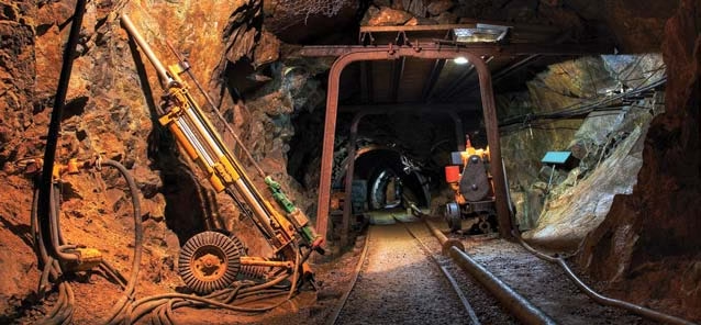
SNAKEFLEX NSSHÖU O/J Cable: Complete Technical Guide
DIN VDE 0250 Part 812 Approved Heavy Duty Submersible Flexible Reeling Cable with Individual Earth Screening & Control Conductors for Extreme Industrial Environments
SNAKEFLEX NSSHÖU O/J represents the pinnacle of heavy-duty flexible cable engineering. Manufactured in strict accordance with DIN VDE 0250 Part 812 standards, this submersible-rated cable features advanced tinned copper conductors and optional individual earth screening for ultimate protection in the most demanding industrial applications. With the ability to operate permanently submersed to 100 meters depth and withstand extreme mechanical abuse, SNAKEFLEX sets the industry standard for reliability in harsh environments.
1. What is SNAKEFLEX NSSHÖU O/J Cable?
SNAKEFLEX is Anhui Feichun’s premium brand of heavy-duty rubber flexible cables specifically engineered for extreme industrial conditions. The NSSHÖU O/J designation represents a specialized cable construction optimized for:
Permanent Submersion
Rated for continuous operation up to 100 meters depth in fresh water, salt water, wastewater, and contaminated environments
Extreme Durability
Heavy-duty construction withstands abrasion, cuts, notches, tears, and severe mechanical stress
Enhanced Protection
Optional individual earth screening eliminates electromagnetic interference and provides superior safety
Integrated Control
Available with dedicated control conductors (ST variant) for signal and monitoring applications
Understanding the Nomenclature
- NSSHÖU – Designates German-standard heavy-duty submersible rubber sheathed cable with enhanced properties
- O/J – Specifies round reeling cable construction for dynamic applications on cable drums and festoon systems
- 0,6/1 kV – Rated voltage designation (600V phase-to-ground / 1000V phase-to-phase)
- SNAKEFLEX – Proprietary brand indicating premium quality construction and materials
Why “SNAKEFLEX”?
The SNAKEFLEX name reflects the cable’s exceptional flexibility and ability to “snake” through complex installation paths while maintaining structural integrity. Like a snake’s ability to navigate harsh terrain, these cables excel in the most challenging industrial environments while providing reliable power transmission through continuous flexing cycles.
2. Cable Variants: O/J, /3E, and /3E+ST
SNAKEFLEX cables are available in three distinct configurations, each optimized for specific application requirements:
Standard Configuration: NSSHÖU O/J
Basic Round Reeling Cable
Configuration: Power conductors with standard rubber insulation and dual sheath protection
Best For: General industrial applications where individual earth screening is not required
Available Configurations: 1-core, 3-core, 4-core, 5-core, 7-core, 12-core, 18-core, 24-core
Conductor Sizes: 1.5 mm² to 300 mm²
Earth Screened Configuration: NSSHÖU…/3E /3E VARIANT
Individually Earth Screened Cores
Configuration: Each phase conductor individually wrapped with copper screen connected to three dedicated earth conductors
Earth Screening:
- Copper braid screening for conductors up to 10 mm²
- Copper wire screening for conductors from 16 mm² and above
- Three earth conductors (3E) sized proportionally to phase conductors
Key Benefits:
- Eliminates electromagnetic interference (EMI) from power conductors
- Provides superior fault protection through low-impedance earth path
- Essential for sensitive electronic equipment installations
- Reduces touch voltage in fault conditions
- Complies with stringent mining and hazardous area regulations
Best For: Mining operations, explosive atmospheres, installations near sensitive electronics, IT power distribution
Available Configurations: 3-core + 3 earth conductors
Conductor Sizes: 2.5 mm² to 185 mm² (phase), proportional earth sizing
Control Conductor Configuration: NSSHÖU…/3E…+ST /3E+ST VARIANT
Earth Screening + Integrated Control Conductors
Configuration: Individually screened phase conductors + three earth conductors + three dedicated control conductors (ST)
Control Conductor Specifications:
- Material: Tinned copper (corrosion resistant)
- Construction: Class 5 VDE 0295 (IEC 60228) – highly flexible
- Insulation: 3GI3 quality rubber compound
- Sizes: 1.5 mm² or 2.5 mm² depending on main conductor size
- Identification: Distinct color coding per VDE 0293-308
Control Conductor Applications:
- Motor control signals (start/stop, speed control, direction)
- Sensor monitoring (temperature, vibration, position)
- Emergency stop circuits
- Status indication and feedback signals
- PLC I/O connections for automated systems
Best For: Automated machinery, crane systems requiring feedback, remote-controlled mobile equipment, integrated power and control applications
Available Configurations: 3-core + 3 earth conductors + 3 control conductors
Conductor Sizes: 2.5 mm² to 185 mm² (phase), proportional earth and control sizing
✓ Variant Selection Guide
| Application Requirement | Recommended Variant | Key Reason |
|---|---|---|
| General crane festoon systems | NSSHÖU O/J | Cost-effective, sufficient for most applications |
| Mining operations | NSSHÖU…/3E | Individual screening required by regulations |
| Explosive atmospheres (ATEX zones) | NSSHÖU…/3E | Enhanced safety through EMI elimination |
| Near sensitive electronics | NSSHÖU…/3E | Prevents electromagnetic interference |
| Automated crane systems | NSSHÖU…/3E+ST | Integrated power and control in single cable |
| Remote-controlled equipment | NSSHÖU…/3E+ST | Eliminates need for separate control cables |
| Submersible pump installations | NSSHÖU O/J or /3E | Waterproof construction suitable for immersion |
3. Primary Purpose and Applications
SNAKEFLEX cables are engineered for the most demanding industrial applications where conventional cables fail. Their unique combination of submersibility, mechanical durability, and optional earth screening makes them the preferred choice across multiple industries.
Primary Industrial Applications
- Underground Mining: Power supply and control for mining equipment, conveyor systems, shuttle cars, and continuous miners operating in wet, abrasive environments with explosive atmosphere risk. Individual earth screening provides critical safety in methane-rich zones.
- Quarry Operations: Heavy-duty power transmission for rock crushers, excavators, and mobile drilling rigs exposed to extreme dust, vibration, and mechanical stress. Submersion capability handles unexpected water accumulation.
- Port and Harbor Equipment: Crane festoon systems for ship-to-shore cranes, container handlers, and mobile harbor cranes operating in corrosive salt water spray environments. Tinned copper conductors prevent galvanic corrosion.
- Wastewater Treatment Plants: Submersible pump power supply for sewage pumps, aerators, and sludge handling equipment. Rated for permanent immersion in contaminated water with resistance to chemicals and biological agents.
- Dredging Operations: Power transmission for cutter heads, ladder systems, and discharge pumps on dredging vessels. Withstands continuous immersion in abrasive sand-water mixtures.
- Offshore Wind Farms: Cable connections for service cranes and mobile maintenance equipment on offshore platforms. Combines salt water resistance with UV stability and ozone resistance.
- Steel Mills and Foundries: High-temperature resistant power supply for ladle cranes, casting cranes, and material handling systems. Oil and grease resistance critical in these environments.
- Agricultural Irrigation: Deep well submersible pump applications for irrigation systems. Long-term reliability in seasonal wet/dry cycling conditions.
- Tunnel Construction: Mobile equipment power supply in wet tunnel environments with requirement for flame retardancy and mechanical protection against falling rock.
- Desalination Plants: Submersible pump power supply in high-salinity water with requirement for long-term corrosion resistance and reliability.
Unique Submersion Capability
According to IEC testing standards, SNAKEFLEX cables are certified for permanent immersion to 100 meters depth in multiple water types:
- Fresh Water: Lakes, rivers, water reservoirs
- Salt Water: Ocean, sea water applications
- Brackish Water: Estuaries, coastal areas with mixed salinity
- Wastewater: Sewage treatment, industrial effluent
- Storm Water: Flood control and drainage systems
- Oily Water: Industrial process water contaminated with oils
- Contaminated Water: Mine water, chemical plant drainage
This certification is verified through HD 22.16 testing and internal accelerated aging tests simulating 20+ years of continuous immersion.
4. Key Technical Characteristics
SNAKEFLEX cables incorporate multiple advanced features that distinguish them from standard industrial cables:
⚡ Electrical Performance
Industrial medium voltage rating with 3 kV factory test voltage verification
🔄 Ultra-Flexibility
Maximum flexibility conductor construction for continuous reeling applications
🌊 Submersion Depth
Continuous operation in fresh, salt, waste, and contaminated water
🔥 Flame Retardancy
Self-extinguishing properties for mining and confined space safety
🌡️ Temperature Range
Extreme cold to high temperature performance without degradation
💪 Tensile Strength
Superior pulling strength for challenging installations
🛡️ Corrosion Protection
Enhanced resistance to galvanic corrosion in wet environments
📡 EMI Shielding
Copper screening eliminates electromagnetic interference
Superior Performance Characteristics
- Abrasion Resistance: Heavy-duty 5GM5 rubber outer sheath provides exceptional resistance to mechanical wear, tested per IEC 60811-2-1 with superior performance compared to PVC or standard rubber compounds
- Cut and Tear Resistance: Proprietary rubber formulation resists cuts, notches, and tears that would compromise standard cables. Ideal for environments with sharp edges and rough handling
- Oil and Fat Resistance: Maintains integrity when exposed to industrial oils, greases, hydraulic fluids, and animal fats. Critical for food processing and heavy machinery applications
- Ozone Resistance: Does not crack or degrade when exposed to high ozone concentrations common near electrical equipment and in industrial environments
- Weather Resistance: UV-stable outer sheath suitable for outdoor installations without degradation from sunlight, rain, or temperature cycling
- Low Temperature Flexibility: Remains flexible down to -40°C in static installations and -25°C in mobile applications, crucial for arctic and cold climate operations
- High Short Circuit Rating: 250°C maximum short circuit temperature provides exceptional safety margin during fault conditions
✓ Tinned Copper Advantage
Unlike standard cables with bare copper conductors, SNAKEFLEX utilizes tinned copper conductors, providing critical advantages for harsh environment applications:
- Corrosion Protection: Tin coating prevents oxidation and galvanic corrosion in wet environments, extending cable life by 3-5× compared to bare copper
- Improved Solderability: Tinned conductors facilitate easier and more reliable terminations
- Enhanced Flexibility: Tin coating reduces strand-to-strand friction, improving overall cable flexibility
- Moisture Barrier: Tin provides additional barrier against moisture migration along conductor strands
- Extended Service Life: Particularly beneficial in submersion applications where bare copper would rapidly corrode
This feature makes SNAKEFLEX the optimal choice for marine, mining, and wastewater applications where moisture exposure is constant.
5. Advanced Material Structure
SNAKEFLEX cables feature a sophisticated multi-layer construction with premium materials selected for maximum performance in extreme conditions:
Layer 1: Phase Conductors
Tinned Copper Conductor System
| Material: | Tinned copper (99.9% pure electrolytic copper with tin plating) |
| Construction Class: | Class 5 per VDE 0295 (IEC 60228) – Extra flexible |
| Strand Configuration: | Ultra-fine wire stranding with high strand count for maximum flexibility |
| Conductivity: | Minimum 58 MS/m at 20°C (IACS 100%) |
| Tin Coating: | Minimum 1 micron thickness per IEC 60228 Annex A |
Why Class 5? This represents the finest stranding available for power cables, with strand diameters typically 0.10-0.21mm. For example, a 50mm² conductor contains over 1,000 individual tinned copper wires, enabling tight bending radii and millions of flexing cycles.
Layer 2: Primary Insulation
3GI3 Quality Rubber Compound
| Material Standard: | VDE 0207 Part 20 – 3GI3 quality specification |
| Base Polymer: | Ethylene Propylene Rubber (EPR) or equivalent high-performance elastomer |
| Thickness: | Precisely specified per VDE 0250 Part 812 based on conductor size |
| Dielectric Strength: | Exceeds 3 kV test voltage requirement with safety margin |
| Temperature Rating: | 90°C continuous, 250°C short circuit (5 seconds maximum) |
| Identification: | Color-coded per VDE 0293 Part 308 (HD 308) |
Material Properties: The 3GI3 compound provides excellent electrical insulation, flexibility across extreme temperatures, resistance to oils and chemicals, and long-term aging stability essential for submersion applications.
Layer 3: Individual Core Screening (3E Variant Only)
Copper EMI Shielding
| Material: | Bare copper (high conductivity for low-impedance earth path) |
| Construction (≤10 mm²): | Copper braid – woven copper wire mesh providing 85-95% coverage |
| Construction (≥16 mm²): | Copper wire screen – helically applied copper wires |
| Function: | Faraday cage effect isolates each phase conductor electromagnetically |
| Earth Connection: | Screens connected to three dedicated earth conductors (3E) |
Technical Benefit: Individual screening provides superior EMI/RFI suppression compared to overall cable screening. Each phase is independently shielded, preventing cross-talk and ensuring sensitive electronic equipment operates without interference. Critical for installations near PLCs, variable frequency drives, and instrumentation.
Layer 4: Control Conductors (/3E+ST Variant Only)
Integrated Control Circuit
| Conductor Material: | Tinned copper (corrosion resistant) |
| Construction Class: | Class 5 VDE 0295 (IEC 60228) – matches main conductor flexibility |
| Insulation Material: | 3GI3 quality rubber compound (VDE 0207 Part 20) |
| Cross-Sections: | 1.5 mm² (for main conductors ≤10 mm²) 2.5 mm² (for main conductors ≥16 mm²) |
| Number of Conductors: | 3 × control conductors (designated “ST” – Steuerleitungen) |
| Voltage Rating: | 300/500V for control circuit applications |
Application Note: Control conductors eliminate the need for separate control cables in automated systems. Common uses include motor control signals, limit switches, emergency stops, position sensors, and PLC I/O connections.
Layer 5: Inner Sheath
GM1b Quality Rubber Compound
| Material Standard: | VDE 0207 Part 21 – GM1b quality specification |
| Function: | Binds all cores into round cable profile, provides additional mechanical and electrical protection |
| Properties: | Oil resistant, water resistant, provides barrier against moisture ingress |
| Flexibility: | Maintains cable flexibility while preventing core separation during bending |
Layer 6: Outer Sheath (Primary Protection)
5GM5 Quality Heavy-Duty Rubber Compound
| Material Standard: | VDE 0207 Part 21 – 5GM5 quality (highest grade for industrial cables) |
| Base Polymer: | Chloroprene rubber (CR) or equivalent marine-grade elastomer |
| Hardness: | Shore A 65-75 (optimal balance of abrasion resistance and flexibility) |
| Tensile Strength: | Minimum 10 N/mm² (exceeds VDE minimum requirement) |
| Elongation at Break: | Minimum 350% (demonstrates exceptional elasticity) |
| Abrasion Resistance: | Maximum 150 mm³ volume loss per IEC 60811-2-1 |
| Ozone Resistance: | No cracking after 96 hours at 50 pphm ozone concentration |
| Oil Resistance: | Maximum 25% mass change after 168 hours IEC oil immersion test |
5GM5 Significance: This represents the most robust sheath material specified in VDE standards. The compound is specifically formulated for extreme mechanical stress, chemical exposure, and water immersion. It provides the primary defense against abrasion, cuts, tears, and environmental degradation.
Material Selection Philosophy
Every material in SNAKEFLEX construction is selected to work synergistically:
- Tinned copper prevents galvanic corrosion in wet environments
- 3GI3 insulation provides electrical protection and flexibility
- Individual screening (3E) eliminates EMI and enhances safety
- GM1b inner sheath prevents water ingress and binds cores
- 5GM5 outer sheath withstands mechanical abuse and chemicals
This comprehensive material system enables SNAKEFLEX to operate reliably in conditions that would destroy conventional cables within months.
6. Compliance with International Standards
SNAKEFLEX cables are manufactured in strict compliance with multiple German and international standards, ensuring quality, safety, and regulatory compliance worldwide:
Primary Manufacturing Standards
| Standard | Title / Scope | Compliance Aspect |
|---|---|---|
| DIN VDE 0250-812 | Power cables with rated voltages up to 450/750 V – Part 812: Heavy duty rubber sheathed cables | Primary design standard defining construction, materials, and performance requirements |
| VDE 0295 (IEC 60228) | Conductors of insulated cables | Class 5 conductor construction, cross-sectional areas, and DC resistance values |
| VDE 0207-20 | Cables and flexible cords – Part 20: Rubber insulation compounds | 3GI3 quality insulation material properties, testing, and acceptance criteria |
| VDE 0207-21 | Cables and flexible cords – Part 21: Rubber sheath compounds | GM1b inner sheath and 5GM5 outer sheath specifications and performance |
| VDE 0293-308 (HD 308) | Identification of cores in cables and flexible cords | Color coding system for phase conductors, neutral, earth, and control conductors |
| VDE 0298-3 | Application of cables – Part 3: Recommended minimum bending radii | Installation bending radius calculations for fixed and reeling applications |
| VDE 0298-4 | Application of cables – Part 4: Current-carrying capacity calculations | Current rating determination including derating factors |
| IEC 60332-1-2 | Tests on electric cables under fire conditions – Single vertical insulated wire or cable flame test | Flame retardancy verification for mining and confined space safety |
| IEC 60811-2-1 | Common test methods for insulating and sheathing materials – Methods specific to elastomeric compounds | Oil resistance, ozone resistance, and mechanical property testing |
| HD 22.16 | Cables for general applications – Rubber or plastics insulated cables for use in water | Submersion capability verification and long-term water immersion testing |
Testing and Quality Assurance
Each production batch undergoes rigorous multi-stage testing according to VDE testing protocols:
Routine Tests (100% Production)
- High Voltage Test: 3 kV AC applied for 5 minutes to verify insulation integrity
- Conductor Resistance: Measurement at 20°C to verify compliance with IEC 60228
- Dimensional Verification: Outer diameter, wall thickness, concentricity measurements
- Visual Inspection: Surface quality, marking legibility, construction uniformity
Type Tests (New Designs/Annual Verification)
- Mechanical Tests: Tensile strength, elongation, cold bend test (-25°C), impact resistance
- Thermal Aging: 168 hours at elevated temperature to simulate long-term aging
- Flame Retardancy: IEC 60332-1-2 vertical flame test with self-extinguishing verification
- Oil Resistance: 168 hours immersion in IEC reference oil at 85°C
- Submersion Test: HD 22.16 water immersion with electrical testing
- Screening Effectiveness: Transfer impedance measurement for /3E variants
Sample Tests (Periodic Quality Verification)
- Ozone Resistance: 96 hours exposure at 40°C to 50 pphm ozone
- Weather Resistance: UV exposure and thermal cycling per IEC 60068-2
- Abrasion Resistance: Rotary drum test per IEC 60811-2-1
- Flexing Endurance: 50,000 cycle bending test for reeling applications
- Salt Spray: 1000 hours salt fog test per IEC 60068-2-52 for marine applications
✓ Regulatory Compliance
European Union: SNAKEFLEX cables comply with the Low Voltage Directive (LVD) 2014/35/EU and carry CE marking for free circulation within EU member states.
Mining Regulations: Suitable for use in underground mining applications where individual earth screening is required by local mining authorities.
ATEX/IECEx: When specified with individual screening (/3E variant), suitable for use in explosive atmospheres per ATEX Directive 2014/34/EU (subject to complete system certification).
Marine Classification: Materials and construction meet requirements for marine classification society approval (subject to application-specific testing).
7. Safety Thresholds and Ratings
Understanding and respecting safety thresholds is critical for reliable operation and personnel protection:
Electrical Safety Parameters
| Parameter | Value | Safety Consideration |
|---|---|---|
| Nominal Rated Voltage (U₀/U) | 0,6/1 kV | Maximum safe operating voltage; never exceed 1.2 kV AC or 1.8 kV DC |
| Factory Test Voltage | 3 kV AC | Applied during manufacturing; field testing should use lower voltages per VDE 0100 |
| Maximum AC Voltage | 0,7/1,2 kV | 20% overvoltage capability for transient conditions only |
| Maximum DC Voltage | 1,8 kV | For DC traction and industrial battery applications |
| Current Rating | Per VDE 0298-4 | Varies with installation method, grouping, and ambient temperature |
| Control Circuit Voltage | 300/500V max | For control conductors (ST variant) only |
Thermal Safety Limits
| Temperature Condition | Value | Safety Implication |
|---|---|---|
| Maximum Conductor Temperature (Continuous) | +90°C | Exceeding causes accelerated insulation aging; monitor load carefully |
| Maximum Short Circuit Temperature | +250°C | 5-second maximum duration; protection devices must clear faults quickly |
| Ambient Temperature: Mobile Applications | -25°C to +80°C | For continuous flexing on cable reels and festoon systems |
| Ambient Temperature: Static Installations | -40°C to +80°C | For fixed installations without mechanical movement |
| Installation Temperature | Minimum -10°C | Allow cable to warm above this temperature before handling to prevent cracking |
Mechanical Safety Parameters
| Mechanical Parameter | Specification | Critical Safety Notes |
|---|---|---|
| Minimum Bending Radius (Fixed) | 15× outer diameter | For permanent installations; tighter bends damage conductors |
| Minimum Bending Radius (Reeling) | 20× outer diameter | For cable drums and dynamic applications; use larger drums when possible |
| Maximum Tensile Load | 15 N/mm² | Based on total phase conductor cross-section; NEVER exceed during installation |
| Maximum Submersion Depth | 100 meters | Continuous rating; exceeding this depth may compromise cable integrity |
| Hydrostatic Pressure | 10 bar (at 100m) | Cable construction withstands this pressure without deformation |
⚠️ CRITICAL SAFETY WARNINGS
- Tensile Load: Exceeding 15 N/mm² can separate conductor strands and damage insulation, creating shock hazards. Always use calibrated tension monitoring during installation.
- Submersion Depth: Operating below 100 meters depth may cause water ingress through cable ends if not properly sealed. Ensure all terminations use appropriate submersible cable glands rated for the installation depth.
- Bending Radius: Violating minimum bending radius causes permanent conductor damage that may not be immediately visible. Damage accumulates over time leading to premature failure.
- Short Circuit Protection: Install appropriately rated circuit breakers or fuses to ensure fault clearance within 5 seconds. Prolonged short circuits exceeding 250°C will destroy cable insulation.
- Earth Screening Connection: For /3E variants, individual screens MUST be properly connected to earth conductors and system ground. Failure to do so eliminates EMI protection and creates safety hazard.
Current Carrying Capacity Guidelines
Current ratings must be calculated according to VDE 0298 Part 4 considering multiple factors:
Derating Factors to Consider
- Installation Method:
- Festoon system: Reference method, base rating
- Cable reel (coiled): Significant derating required (typically 0.6-0.8 factor)
- Direct burial: Enhanced cooling, may allow uprating
- In conduit/duct: Reduced cooling, requires derating
- Ambient Temperature:
- Base rating at 30°C reference
- 40°C ambient: multiply by 0.87
- 50°C ambient: multiply by 0.71
- 60°C ambient: multiply by 0.50
- Grouping Factor:
- Single circuit: Factor = 1.0
- 2-3 circuits in contact: Factor = 0.8
- 4-6 circuits in contact: Factor = 0.7
- Duty Cycle:
- Continuous duty (100%): Base rating
- Intermittent duty (40%): May allow 1.15× uprating
- Short-time duty (15%): May allow 1.3× uprating
- Water Submersion:
- Enhanced cooling allows potential uprating
- Consult manufacturer for specific submersion derating/uprating factors
- Water temperature affects cooling capability
8. Installation and Usage Precautions
Proper installation is critical for SNAKEFLEX cables to achieve their designed service life and performance:
Pre-Installation Considerations
- Cable Storage: Store drums in covered area, protected from direct sunlight and precipitation. Temperature range: -10°C to +40°C. Do not stack more than 3 drums high. Rotate drums quarterly if storage exceeds 6 months.
- Inspection Protocol: Before installation, unroll 10 meters and inspect for:
- Outer sheath cuts, abrasions, or deformations
- Crushing damage from improper handling or storage
- Marking legibility and accuracy
- Correct cable variant (O/J, /3E, or /3E+ST) matches specifications
- Temperature Acclimatization: If cable has been stored below 0°C, allow 24-48 hours at ambient temperature before installation to prevent insulation damage during handling.
- Installation Planning:
- Calculate total cable length including slack for reeling systems (typically 10-15% extra)
- Identify all bend points and verify minimum radius compliance
- Plan support locations at maximum 1.5-meter intervals
- Ensure pulling route is clear of sharp edges and obstructions
Installation Best Practices
🔧 Mechanical Installation
- Use pulling grips rated for cable diameter and weight
- Never pull around corners >90° without cable rollers
- Monitor pulling tension continuously; stop if exceeding 70% of maximum rated load
- Use appropriate lubricant for long pulls (water-based, compatible with rubber)
- Protect cable from sharp edges with rubber guards or wrap
📏 Bending Radius Compliance
- Static installations: minimum 15× outer diameter
- Reeling applications: minimum 20× outer diameter
- Use cable drum diameter calculator: D = 20 × cable OD
- Avoid reverse bends within 1-meter distance
- Use templates to verify bend radii during installation
⚡ Electrical Terminations
- Use only compression lugs rated for tinned copper
- Clean tin surface before termination (light abrasion)
- Apply anti-oxidant compound to terminations
- Torque lugs to manufacturer specifications
- For /3E variant: Connect all screens to earth conductors
- For /3E+ST: Maintain separation between power and control circuits
🌊 Submersion Installations
- Use IP68-rated submersible cable glands at all entries
- Apply heat-shrink sealing at cable ends
- Install weight anchors to prevent floating
- Provide strain relief at all terminations
- Verify depth rating matches installation depth
Festoon System Installation
For crane festoon applications, follow these specific guidelines:
- Trolley Selection:
- Roller diameter: Minimum 15× cable outer diameter
- Roller material: Polyurethane or nylon (not metal)
- Bearing type: Sealed ball bearings, maintenance-free
- Trolley spacing: Maximum 1.5 meters for cables up to 30mm OD, 1.0 meter for larger cables
- Cable Support Configuration:
- Form natural loops between trolleys without forcing cable
- Initial loop length: Allow full travel plus 15% margin
- Prevent cable twist by maintaining natural lay orientation
- Install guide rollers at direction changes
- Track Alignment:
- Ensure festoon track is straight within ±5mm over 10-meter span
- Level track within ±2mm per meter
- Misalignment causes uneven wear and premature cable failure
- Cable Entry to Mobile Equipment:
- Use flexible cable entry with minimum 300mm bend radius
- Install strain relief that allows cable movement
- Never clamp cable rigidly at entry point
- Provide additional cable loop for stress absorption
Cable Reel Installation
For cable reel applications on mobile equipment:
- Drum Specifications:
- Minimum drum diameter: 20× cable outer diameter (critical)
- Drum width: Ensure even spooling without crossing
- Flange height: Minimum 1.5× cable diameter to prevent unwinding
- Core diameter: Adequate for maximum layers without damage
- Spooling Technique:
- Wind first layer tightly and uniformly – foundation for all subsequent layers
- Maintain constant light tension (2-5% of tensile load rating)
- Avoid gaps between wraps that allow cable to wedge into lower layers
- Mark layer transitions for operational reference
- Fleet Angle Management:
- Maximum fleet angle: 2° from perpendicular to drum
- Exceeding 2° causes side loading and premature wear
- Use level wind mechanism for cables >25mm diameter
- Adjust cable guide position as drum fills
- Electrical Connection:
- Use slip rings rated for full cable current capacity
- Slip ring current rating: 125% of cable rating minimum
- Regular inspection and maintenance of slip ring contacts
- For /3E+ST variant: Ensure separate slip rings for power, earth, and control circuits
Submersion Installation Procedures
Waterproofing Terminations
Proper termination is critical for submersion applications:
- Cable Preparation:
- Remove outer sheath carefully to avoid damaging inner sheath
- For /3E variant: Fold back individual screens and connect to earth conductors
- Clean and dry all conductor surfaces before termination
- Gland Installation:
- Use only IP68-rated submersible cable glands
- Ensure gland depth rating exceeds installation depth by 50%
- Follow manufacturer torque specifications precisely
- Verify O-ring seals are undamaged and properly seated
- Heat Shrink Sealing:
- Apply heat-shrink tubing over gland/cable interface
- Use marine-grade adhesive-lined heat shrink
- Ensure complete seal without voids or wrinkles
- Allow cooling period before submersion
- Pressure Testing:
- Perform hydrostatic pressure test to 1.5× installation depth
- Monitor for 24 hours before final installation
- Any leakage requires complete re-termination
Maintenance Requirements
| Maintenance Task | Frequency | Detailed Procedure |
|---|---|---|
| Visual Inspection | Weekly | Check for visible damage, wear, contamination, proper support, festoon trolley operation |
| Cleaning | Monthly | Remove dust, oil, and contamination using mild detergent and soft cloth; rinse and dry |
| Support System Check | Monthly | Verify cable supports, strain relief, festoon trolley function, drum rotation smoothness |
| Bending Cycle Count | Monthly | For reeling applications, track cycles and plan replacement before service life limit |
| Electrical Testing | Annually | Insulation resistance (500V megger), continuity, earth bond, visual inspection of terminations |
| Submersion Inspection | Semi-annually | For submerged cables: retrieve and inspect glands, check for water ingress, verify seal integrity |
| Comprehensive Assessment | Every 2-3 years | Complete electrical testing, thermal imaging under load, mechanical condition assessment |
9. Submersion Guidelines
SNAKEFLEX’s unique 100-meter submersion capability requires specific installation and operational considerations:
Water Type Compatibility
| Water Type | Suitability | Special Considerations |
|---|---|---|
| Fresh Water | ✓ Excellent | Lowest corrosion risk; standard termination procedures sufficient |
| Salt Water | ✓ Excellent | Tinned copper prevents galvanic corrosion; use marine-grade terminations |
| Brackish Water | ✓ Excellent | Variable salinity; periodic inspection of terminations recommended |
| Wastewater (Sewage) | ✓ Very Good | May contain aggressive biological agents; annual gland inspection required |
| Storm Water | ✓ Excellent | Variable pH; material selection appropriate for full pH range |
| Oily Water | ✓ Very Good | Oil resistance verified per IEC 60811-2-1; regular cleaning recommended |
| Mine Water | ✓ Good | May be acidic; verify pH range and consult manufacturer for extreme conditions |
| Chemical Process Water | ⚠ Consult Manufacturer | Depends on specific chemicals present; material compatibility testing may be required |
Depth-Pressure Relationship
Hydrostatic Pressure Calculations
Understanding pressure is critical for submersion applications:
- 10 meters depth = 1 bar (14.5 psi) = 0.1 MPa
- 50 meters depth = 5 bar (72.5 psi) = 0.5 MPa
- 100 meters depth = 10 bar (145 psi) = 1.0 MPa
SNAKEFLEX construction is designed to withstand 10 bar continuous pressure without deformation or water ingress. The heavy-duty 5GM5 outer sheath and GM1b inner sheath provide dual barriers against water penetration.
Temperature Effects in Water
- Cold Water (0-10°C): Enhanced current carrying capacity due to superior cooling; calculate uprating factor based on thermal conductivity
- Temperate Water (10-25°C): Standard current ratings apply; optimal operating condition
- Warm Water (25-40°C): Reduced cooling effectiveness; may require derating depending on load profile
- Hot Water (>40°C): Significant derating required; consult manufacturer for specific calculations
Installation Depth Guidelines
- 0-30 meters: Standard installation procedures; verify glands rated for minimum IP68
- 30-70 meters: Enhanced termination procedures recommended; use marine-grade heat shrink; pressure test to 1.5× depth
- 70-100 meters: Maximum rated depth; use highest-quality submersible glands; conduct hydrostatic test to 15 bar; annual inspection mandatory
- >100 meters: Consult manufacturer; may require custom construction with reinforced sheaths
Buoyancy and Weight Management
Cable Weight in Water
SNAKEFLEX cables have negative buoyancy (sink) but should be properly weighted:
- Apparent Weight: Approximately 50-60% of air weight when submerged
- Weight Calculation: Wwater = Wair – (V × ρwater), where V is cable volume and ρ is water density
- Anchoring: Install weights every 10-20 meters to prevent movement from currents
- Vertical Installations: Support cable at regular intervals to prevent tensile stress from cable weight
10. Common Problems and Solutions
Addressing common issues ensures maximum service life and reliability:
Problem 1: Water Ingress in Submerged Applications
Symptoms: Reduced insulation resistance, intermittent faults, visible moisture in cable glands, corrosion at terminations
Root Causes:
- Improper gland installation or selection
- Damaged cable end during installation
- Exceeded depth rating
- Mechanical damage to outer sheath allowing water penetration
Solutions:
- Verify all glands are IP68-rated and depth-appropriate
- Re-terminate using proper procedures: clean, dry, heat-shrink seal
- Perform hydrostatic pressure test before deployment
- Inspect cable length for sheath damage; replace damaged sections
- Once water ingress occurs, complete cable section replacement usually required
- Install sacrificial anodes at terminations in salt water to prevent galvanic corrosion
Problem 2: Individual Screen Failure (/3E Variant)
Symptoms: Electromagnetic interference affecting connected equipment, nuisance tripping of RCDs, increased touch voltage
Root Causes:
- Screens not properly connected to earth conductors
- Earth conductors not connected to system ground
- Screen damage during installation or operation
- Corrosion of screen connection points
Solutions:
- Verify all individual screens are connected to the three earth conductors
- Ensure earth conductors are properly bonded to system ground at both ends
- Use multimeter to verify continuity of screen to earth path (should be <1 ohm)
- Inspect screen connection points for corrosion; clean and protect
- For submersion applications, ensure screen terminations are waterproofed
- Test transfer impedance periodically to verify screening effectiveness
Problem 3: Premature Abrasion in Festoon Systems
Symptoms: Visible wear on cable outer sheath, flat spots, localized thinning, eventual exposure of inner layers
Root Causes:
- Worn or damaged festoon trolley rollers
- Incorrect roller diameter (too small causing excessive pressure)
- Misaligned festoon track causing uneven loading
- Contamination (abrasive dust, metal particles) on rollers
Solutions:
- Inspect and replace worn trolley rollers (rotate freely without binding)
- Verify roller diameter meets minimum 15× cable OD requirement
- Check festoon track alignment; straightness within ±5mm per 10m
- Implement regular cleaning schedule for trolleys and cable
- Consider upgrading to larger diameter rollers to reduce pressure
- Rotate cable 180° periodically to distribute wear evenly
Problem 4: Cable Twisting on Reels
Symptoms: Cable develops visible spiral twist, binding during reeling, uneven spooling, premature fatigue failure
Root Causes:
- Improper initial spooling technique
- Excessive fleet angle (>2°)
- Cable wound under excessive tension
- Drum diameter too small causing internal stress
Solutions:
- Completely unwind and re-spool cable ensuring tight, even first layer
- Adjust cable guide to maintain fleet angle <2° throughout travel
- Monitor spooling tension; maintain 2-5% of rated tensile load
- Verify drum diameter meets minimum 20× cable OD requirement
- Install level wind mechanism for large diameter cables (>25mm)
- Once permanent twist develops, cable replacement typically required
Problem 5: Control Circuit Interference (/3E+ST Variant)
Symptoms: Erratic control signals, false triggering, unreliable sensor readings, communication errors
Root Causes:
- Control circuits not properly separated from power circuits
- Inadequate earth screening or improper screen connection
- Control conductors used for excessive current
- EMI from external sources coupling into control circuits
Solutions:
- Verify physical separation between power and control terminations
- Confirm all individual power conductor screens properly connected to earth
- Measure control circuit current; should not exceed 2A continuous
- Use screened/twisted pair control cables for long runs if interference persists
- Implement proper grounding practices at control equipment end
- Consider using fiber optic communication for critical control signals
Problem 6: Thermal Overload
Symptoms: Hot spots detectable by touch or thermal imaging, accelerated sheath aging, insulation breakdown
Root Causes:
- Current loading exceeds calculated rating for installation conditions
- Poor termination creating high resistance connection
- Cable reeled with insufficient cooling (multiple layers)
- Ambient temperature exceeds design assumptions
Solutions:
- Measure actual current and verify against VDE 0298-4 calculated rating
- Apply appropriate derating factors: temperature, installation method, grouping
- Inspect and retorque all terminations to specified values
- For reeled applications, calculate derating for coiled configuration
- Improve ventilation or reduce ambient temperature if possible
- Consider upgrading to larger conductor size if sustained overload required
- Install temperature sensors for continuous monitoring in critical applications
⚠️ When to Replace Cable
Immediate replacement required if:
- Outer sheath worn through exposing inner layers
- Visible conductor strands at any point
- Insulation resistance below 1 MΩ (measured at 500V DC)
- Evidence of internal water penetration
- Mechanical damage compromising structural integrity
- Thermal damage from overload or short circuit
- Permanent twist or deformation preventing proper spooling
- Flexing cycles exceed manufacturer-specified service life
Never attempt field repairs of insulation or sheath damage. Compromised cables create severe safety hazards and must be replaced.
11. Technical Specifications and Dimensions
Complete technical specifications for all SNAKEFLEX NSSHÖU cable variants:
Standard Configuration: NSSHÖU O/J (Single and Three-Core)
| Voltage (kV) | Cores × Size (Nr × mm²) | Conductor Ø (mm) | Min Overall Ø (mm) | Max Overall Ø (mm) | Approx Weight (kg/km) | Max Tensile Load (N) |
|---|---|---|---|---|---|---|
| 0,6/1 | 1×1,5 | 1,5 | 6,3 | 7,0 | 60 | 23 |
| 0,6/1 | 1×2,5 | 1,9 | 7,0 | 7,7 | 75 | 38 |
| 0,6/1 | 1×4 | 2,4 | 7,6 | 8,3 | 95 | 60 |
| 0,6/1 | 1×6 | 2,9 | 8,2 | 8,9 | 120 | 90 |
| 0,6/1 | 1×10 | 3,8 | 9,5 | 10,2 | 180 | 150 |
| 0,6/1 | 1×16 | 4,8 | 10,5 | 11,2 | 245 | 240 |
| 0,6/1 | 1×25 | 6,1 | 13,0 | 13,7 | 375 | 375 |
| 0,6/1 | 1×35 | 7,2 | 14,1 | 14,8 | 480 | 525 |
| 0,6/1 | 1×50 | 8,9 | 16,2 | 16,9 | 660 | 750 |
| 0,6/1 | 1×70 | 10,6 | 18,3 | 19,0 | 875 | 1050 |
| 0,6/1 | 1×95 | 12,5 | 20,5 | 21,7 | 1150 | 1425 |
| 0,6/1 | 1×120 | 14,2 | 22,8 | 24,0 | 1430 | 1800 |
| 0,6/1 | 1×150 | 15,9 | 25,0 | 26,2 | 1750 | 2250 |
| 0,6/1 | 1×185 | 17,7 | 28,2 | 29,4 | 2180 | 2775 |
| 0,6/1 | 1×240 | 20,1 | 31,1 | 32,3 | 2770 | 3600 |
| 0,6/1 | 1×300 | 22,5 | 34,9 | 36,1 | 3510 | 4500 |
| 0,6/1 | 3×1,5 | 1,5 | 11,7 | 12,3 | 190 | 68 |
| 0,6/1 | 3×2,5 | 1,9 | 13,1 | 13,7 | 255 | 113 |
| 0,6/1 | 3×4 | 2,4 | 15,6 | 16,2 | 375 | 180 |
| 0,6/1 | 3×6 | 2,9 | 16,8 | 17,4 | 465 | 270 |
| 0,6/1 | 3×10 | 3,8 | 20,2 | 21,3 | 710 | 450 |
| 0,6/1 | 3×16 | 4,8 | 22,3 | 23,4 | 930 | 720 |
| 0,6/1 | 3×25 | 6,1 | 26,9 | 28,0 | 1390 | 1125 |
| 0,6/1 | 3×35 | 7,2 | 30,2 | 31,4 | 1880 | 1575 |
| 0,6/1 | 3×50 | 8,9 | 35,8 | 37,0 | 2500 | 2250 |
| 0,6/1 | 3×70 | 10,6 | 39,3 | 40,5 | 3460 | 3150 |
| 0,6/1 | 3×95 | 12,5 | 45,7 | 47,4 | 4570 | 4275 |
| 0,6/1 | 3×120 | 14,2 | 48,2 | 49,9 | 5220 | 5400 |
| 0,6/1 | 3×150 | 15,9 | 52,6 | 54,4 | 6460 | 6750 |
| 0,6/1 | 3×185 | 17,7 | 58,7 | 61,0 | 7980 | 8325 |
Standard Configuration: NSSHÖU O/J (Multi-Core)
| Voltage (kV) | Cores × Size (Nr × mm²) | Conductor Ø (mm) | Min Overall Ø (mm) | Max Overall Ø (mm) | Approx Weight (kg/km) | Max Tensile Load (N) |
|---|---|---|---|---|---|---|
| 0,6/1 | 3×50 + 3×25/3 | 8,9 | 36,3 | 37,5 | 2790 | 2250 |
| 0,6/1 | 3×70 + 3×35/3 | 10,6 | 39,7 | 41,4 | 3660 | 3150 |
| 0,6/1 | 3×95 + 3×50/3 | 12,5 | 46,3 | 48,0 | 4800 | 4275 |
| 0,6/1 | 3×120 + 3×70/3 | 14,2 | 48,5 | 50,3 | 5990 | 5400 |
| 0,6/1 | 3×150 + 3×70/3 | 15,9 | 54,3 | 56,1 | 7030 | 6750 |
| 0,6/1 | 3×185 + 3×95/3 | 17,7 | 61,7 | 64,0 | 9030 | 8325 |
| 0,6/1 | 3×240 + 3×120/3 | 20,1 | 66,5 | 68,8 | 11280 | 10800 |
| 0,6/1 | 4×1,5 | 1,5 | 12,5 | 13,1 | 225 | 90 |
| 0,6/1 | 4×2,5 | 1,9 | 15,3 | 15,9 | 350 | 150 |
| 0,6/1 | 4×4 | 2,4 | 16,7 | 17,3 | 440 | 240 |
| 0,6/1 | 4×6 | 2,9 | 18,1 | 18,7 | 550 | 360 |
| 0,6/1 | 4×10 | 3,8 | 21,9 | 23,0 | 860 | 600 |
| 0,6/1 | 4×16 | 4,8 | 25,2 | 26,3 | 1210 | 960 |
| 0,6/1 | 4×25 | 6,1 | 30,6 | 31,8 | 1810 | 1500 |
| 0,6/1 | 4×35 | 7,2 | 32,8 | 34,0 | 2330 | 2100 |
| 0,6/1 | 4×50 | 8,9 | 39,0 | 40,2 | 3300 | 3000 |
| 0,6/1 | 4×70 | 10,6 | 42,8 | 44,5 | 4300 | 4200 |
| 0,6/1 | 4×95 | 12,5 | 49,9 | 51,7 | 5680 | 5700 |
| 0,6/1 | 4×120 | 14,2 | 55,6 | 57,4 | 6820 | 7200 |
| 0,6/1 | 4×150 | 15,9 | 60,6 | 62,9 | 8270 | 9000 |
| 0,6/1 | 4×185 | 17,7 | 67,4 | 69,7 | 10350 | 11100 |
| 0,6/1 | 5×1,5 | 1,5 | 13,4 | 14,0 | 270 | 113 |
| 0,6/1 | 5×2,5 | 1,9 | 16,4 | 17,0 | 410 | 188 |
| 0,6/1 | 5×4 | 2,4 | 18,0 | 18,6 | 525 | 300 |
| 0,6/1 | 5×6 | 2,9 | 20,3 | 21,4 | 715 | 450 |
| 0,6/1 | 5×10 | 3,8 | 23,7 | 24,8 | 1040 | 750 |
| 0,6/1 | 5×16 | 4,8 | 27,3 | 28,4 | 1470 | 1200 |
| 0,6/1 | 5×25 | 6,1 | 33,2 | 34,4 | 2220 | 1875 |
| 0,6/1 | 7×1,5 | 1,5 | 16,9 | 17,5 | 400 | 158 |
| 0,6/1 | 7×2,5 | 1,9 | 19,2 | 19,8 | 560 | 263 |
| 0,6/1 | 12×1,5 | 1,5 | 19,6 | 20,2 | 540 | 270 |
| 0,6/1 | 12×2,5 | 1,9 | 22,3 | 23,4 | 790 | 450 |
| 0,6/1 | 18×1,5 | 1,5 | 22,2 | 23,3 | 750 | 405 |
| 0,6/1 | 18×2,5 | 1,9 | 26,5 | 27,6 | 1110 | 675 |
| 0,6/1 | 24×1,5 | 1,5 | 23,7 | 25,1 | 900 | 540 |
| 0,6/1 | 24×2,5 | 1,9 | 28,4 | 29,6 | 1350 | 900 |
Earth Screened Configuration: NSSHÖU…/3E
| Voltage (kV) | Configuration (Power + Earth) | Conductor Ø (mm) | Min Overall Ø (mm) | Max Overall Ø (mm) | Approx Weight (kg/km) | Max Tensile Load (N) |
|---|---|---|---|---|---|---|
| 0,6/1 | 3×2,5 + 3×2,5/3E | 1,9 | 16,2 | 16,9 | 370 | 113 |
| 0,6/1 | 3×4 + 3×4/3E | 2,4 | 17,7 | 18,4 | 490 | 180 |
| 0,6/1 | 3×6 + 3×6/3E | 2,9 | 18,9 | 19,6 | 590 | 270 |
| 0,6/1 | 3×10 + 3×10/3E | 3,8 | 22,4 | 23,5 | 890 | 450 |
| 0,6/1 | 3×16 + 3×16/3E | 4,8 | 26,6 | 27,7 | 1260 | 720 |
| 0,6/1 | 3×25 + 3×16/3E | 6,1 | 29,9 | 31,1 | 1700 | 1125 |
| 0,6/1 | 3×35 + 3×16/3E | 7,2 | 33,9 | 35,1 | 2100 | 1575 |
| 0,6/1 | 3×50 + 3×25/3E | 8,9 | 39,8 | 41,5 | 3060 | 2250 |
| 0,6/1 | 3×70 + 3×35/3E | 10,6 | 43,4 | 45,1 | 3940 | 3150 |
| 0,6/1 | 3×95 + 3×50/3E | 12,5 | 50,0 | 51,8 | 5240 | 4275 |
| 0,6/1 | 3×120 + 3×70/3E | 14,2 | 54,1 | 55,9 | 6580 | 5400 |
| 0,6/1 | 3×150 + 3×70/3E | 15,9 | 59,7 | 62,0 | 7590 | 6750 |
| 0,6/1 | 3×185 + 3×95/3E | 17,7 | 66,1 | 68,4 | 9400 | 8325 |
Earth Screened + Control Conductor Configuration: NSSHÖU…/3E…+ST
| Voltage (kV) | Configuration (Power + Earth + Control) | Conductor Ø (mm) | Min Overall Ø (mm) | Max Overall Ø (mm) | Approx Weight (kg/km) | Max Tensile Load (N) |
|---|---|---|---|---|---|---|
| 0,6/1 | 3×2,5 + 3×2,5/3E + 3×1,5ST | 1,9 | 16,2 | 18,1 | 425 | 113 |
| 0,6/1 | 3×4 + 3×4/3E + 3×1,5ST | 2,4 | 17,7 | 19,6 | 540 | 180 |
| 0,6/1 | 3×6 + 3×6/3E + 3×1,5ST | 2,9 | 18,9 | 20,3 | 640 | 270 |
| 0,6/1 | 3×10 + 3×10/3E + 3×2,5ST | 3,8 | 22,4 | 23,5 | 940 | 450 |
| 0,6/1 | 3×16 + 3×16/3E + 3×2,5ST | 4,8 | 26,6 | 27,7 | 1310 | 720 |
| 0,6/1 | 3×25 + 3×16/3E + 3×2,5ST | 6,1 | 29,9 | 31,1 | 1800 | 1125 |
| 0,6/1 | 3×35 + 3×16/3E + 3×2,5ST | 7,2 | 33,9 | 35,1 | 2230 | 1575 |
| 0,6/1 | 3×50 + 3×25/3E + 3×2,5ST | 8,9 | 39,8 | 41,5 | 3160 | 2250 |
| 0,6/1 | 3×70 + 3×35/3E + 3×2,5ST | 10,6 | 43,4 | 45,1 | 4210 | 3150 |
| 0,6/1 | 3×95 + 3×50/3E + 3×2,5ST | 12,5 | 50,0 | 51,8 | 5520 | 4275 |
| 0,6/1 | 3×120 + 3×70/3E + 3×2,5ST | 14,2 | 54,1 | 55,9 | 6730 | 5400 |
| 0,6/1 | 3×150 + 3×70/3E + 3×2,5ST | 15,9 | 59,7 | 62,0 | 7740 | 6750 |
| 0,6/1 | 3×185 + 3×95/3E + 3×2,5ST | 17,7 | 66,1 | 68,4 | 9700 | 8325 |
📐 Specification Notes
- Diameter Tolerances: Min/Max overall diameter accounts for manufacturing tolerances per VDE standards
- Weight Variations: Approximate weight may vary ±5% depending on specific construction details
- Tensile Load: Maximum values based on 15 N/mm² applied to total phase conductor cross-section
- Earth Conductor Sizing (/3E): Earth conductors sized per VDE requirements, typically 50-100% of phase conductor size
- Control Conductor Rating (ST): Control circuits rated for 300/500V, maximum 2A continuous current
- Custom Configurations: Other core counts and cross-sections available upon request
Ready to Specify SNAKEFLEX for Your Project?
Our engineering team at Anhui Feichun Special Cable Co., Ltd. provides comprehensive technical support including application analysis, custom cable design, installation guidance, and complete project documentation. Contact us for detailed specifications, samples, and expert consultation.
📧 Contact Technical ExpertsInternational Sales: +86 13855123218
References and Standards Documentation
This comprehensive guide is based on authoritative sources and internationally recognized standards:
- VDE (Verband der Elektrotechnik) – German Association for Electrical, Electronic & Information Technologies
- IEC (International Electrotechnical Commission) – International standards for electrical technologies
- DIN (Deutsches Institut für Normung) – German Institute for Standardization
- CENELEC (European Committee for Electrotechnical Standardization) – European electrical standards
📚 Essential Standards Documents
- DIN VDE 0250-812: Heavy duty rubber sheathed cables – primary construction standard
- IEC 60228: Conductors of insulated cables – Class 5 requirements
- IEC 60332-1-2: Vertical flame test for single cables
- VDE 0298-4: Current-carrying capacity calculations with derating factors
- HD 308 (VDE 0293-308): Harmonized cable core identification
- HD 22.16: Cables for use in water – submersion testing requirements
- IEC 60811-2-1: Test methods for elastomeric compounds – oil and ozone resistance


