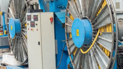
High-Flexibility Mining Cable Reels: Comprehensive Technical Comparison
High-Flexibility Mining Cable Reels: Comprehensive Technical Comparison
Type N/(N)TSCGEWOEU-TR vs (N)TMCGEW11Y Cable Systems for Open-Cast and Underground Mining Applications
Anhui Feichun Special Cable Co., Ltd. (安徽飞纯特种电缆有限公司) | Leading Manufacturer of High-Performance Mining Cables
In the demanding environments of modern mining operations, the selection of appropriate cable systems represents a critical decision that directly impacts operational efficiency, safety, and cost-effectiveness. This comprehensive technical analysis examines two sophisticated high-flexibility crane cable reel systems designed for mining applications: the Type N/(N)TSCGEWOEU-TR trailing cable and the Type (N)TMCGEW11Y mining cable. Both systems have been engineered to meet the rigorous mechanical, electrical, and environmental demands of open-cast and underground mining operations, yet each offers distinct advantages suited to specific operational requirements.
1. Executive Summary: Cable Type Overview and Application Domains
Type N/(N)TSCGEWOEU-TR
- Standard Compliance: DIN VDE 0250-813
- Voltage Range: 3.6/6 kV up to 18/30 kV
- Configuration: 3x…+3x…/3, 3x…+2x…+1x…
- Primary Application: Open-cast mining operations
- Equipment Support: Dragline excavators, shovel excavators, mobile transformers
- Design Philosophy: High-voltage trailing cable with dual rubber sheath construction
Type (N)TMCGEW11Y
- Standard Compliance: Mining industry specifications
- Voltage Range: Up to 15 kV
- Configuration: 3x…+3x…/3
- Primary Application: Underground and open-cast mining
- Equipment Support: Heavy mobile equipment in rough ambient conditions
- Design Philosophy: Extreme abrasion-resistant flexible power supply cable
2. Technical Purpose and Operational Objectives
2.1 Type N/(N)TSCGEWOEU-TR Operational Purpose
The Type N/(N)TSCGEWOEU-TR cable system has been specifically engineered for flexible power transmission in open-cast mining environments where large-scale material handling equipment operates under continuous mechanical stress. The cable designation itself reveals its construction hierarchy: “N” indicates natural rubber insulation, “T” denotes trailing cable application, “S” represents heavy duty construction, “C” signifies copper conductor material, “G” indicates the presence of an earth conductor, “E” denotes EPR (Ethylene Propylene Rubber) insulation type, “W” signifies weather-resistant properties, “OE” indicates oil-resistant outer sheath, “U” represents the cable’s suitability for underground use, and “TR” designates its trailing/reeling application capability.
The voltage range of 3.6/6 kV to 18/30 kV positions this cable system in the medium to high voltage category, enabling it to support power-intensive equipment such as dragline excavators that can handle bucket capacities exceeding 100 cubic meters and shovel excavators with digging forces surpassing 3,000 kN. The dual voltage ratings (e.g., 18/30 kV) indicate the cable’s voltage to earth (18 kV) and voltage between conductors (30 kV), providing critical information for electrical system design and safety calculations.
2.2 Type (N)TMCGEW11Y Operational Purpose
The Type (N)TMCGEW11Y cable system represents a specialized solution engineered for operations in both underground and open-cast mining environments where extreme mechanical abuse, particularly abrasion, constitutes the primary operational challenge. The “TM” designation indicates its trailing/mining classification, while “11Y” signifies its enhanced abrasion resistance characteristics achieved through advanced material formulation and construction techniques.
Operating at voltages up to 15 kV, this cable system addresses the power requirements of heavy mobile equipment including continuous miners (commonly operating with cutting head powers between 300-600 kW), shuttle cars with payload capacities of 10-15 tons, and load-haul-dump (LHD) vehicles with bucket capacities ranging from 4 to 20 cubic yards. The cable’s design philosophy prioritizes mechanical durability over maximum voltage capability, making it ideal for equipment that operates in confined spaces where cable contact with rock surfaces, machinery, and other abrasive materials occurs frequently.
3. Material Structure and Construction Engineering
3.1 Type N/(N)TSCGEWOEU-TR Construction Architecture
The construction of the NTSCGEWOEU-TR cable follows a sophisticated multi-layer architecture designed to achieve optimal electrical performance while maintaining mechanical flexibility. The conductor system typically employs stranded copper conductors conforming to Class 5 or Class 6 flexibility standards as defined by IEC 60228, with conductor cross-sections ranging from 25 mm² to 240 mm² for power cores and proportionally sized earth conductors.
| Construction Layer | Material Composition | Technical Function | Performance Parameter |
|---|---|---|---|
| Conductor Core | Stranded Copper (Class 5/6) | Current conduction and flexibility | Minimum 15 N/mm² tensile strength |
| Conductor Screen | Semi-conductive compound | Electric field control | Max resistivity 200 Ω·m |
| Core Insulation | EPR Type 3GI3 (DIN VDE 0207 Part 20) | Electrical insulation and temperature resistance | Min 300% elongation at break |
| Insulation Screen | Semi-conductive layer | Voltage stress distribution | Max resistivity 200 Ω·m |
| Assembly Structure | Cradle separator with Kevlar reinforcement | Mechanical stress distribution | Min 30 N/mm break load |
| Inner Sheath | Synthetic thermosetting compound 5GM3 | Core bundle protection | Oil and flame resistant |
| Outer Sheath | Synthetic thermosetting compound 5GM5 | Environmental protection and abrasion resistance | High resistance to UV, ozone, weather |
The dual sheath construction represents a critical design element that significantly enhances the cable’s operational reliability. The inner sheath provides a first line of defense against mechanical damage while maintaining flexibility, with typical thickness ranging from 2.0 to 3.5 mm depending on cable diameter. The outer sheath, typically 3.5 to 5.0 mm thick, offers superior resistance to environmental factors including ultraviolet radiation, ozone degradation, chemical exposure from mining operations, and physical abrasion from contact with equipment and terrain.
3.2 Type (N)TMCGEW11Y Construction Architecture
The TMCGEW11Y cable construction emphasizes extreme abrasion resistance through the strategic selection of advanced polymer compounds and reinforcement technologies. The conductor system similarly employs tinned or bare stranded copper conductors, with tin plating providing enhanced corrosion resistance in the humid and chemically aggressive environments typical of underground mining operations.
| Construction Layer | Material Composition | Technical Function | Performance Parameter |
|---|---|---|---|
| Conductor Core | Tinned stranded copper | Current conduction with corrosion protection | Enhanced oxidation resistance |
| Core Insulation | EPR or XLPE compound | Electrical insulation | Operating temp -25°C to +90°C |
| Core Assembly | Cabled with integral filled construction | Enhanced torsion resistance | Superior twist performance |
| Binder Tape | Semi-conducting polymer | Core bundle cohesion | Maintains assembly integrity |
| Outer Sheath | TPU (Thermoplastic Polyurethane) compound | Extreme abrasion resistance | Very high abrasion resistance rating |
| Color Coding | Yellow jacket (standard) | High visibility and identification | Enhanced safety compliance |
The distinctive feature of the TMCGEW11Y design lies in its utilization of Thermoplastic Polyurethane (TPU) as the outer sheath material. TPU compounds offer abrasion resistance characteristics that can exceed conventional rubber compounds by factors of 3 to 5 times under controlled testing conditions. The material exhibits shore hardness values typically ranging from 85A to 95A, providing an optimal balance between flexibility and cut-through resistance. Additionally, TPU demonstrates excellent low-temperature flexibility, maintaining pliability at temperatures as low as -40°C, which proves essential for equipment operating in various climatic conditions.
4. Standards Compliance and Regulatory Framework
4.1 DIN VDE 0250-813 Compliance Framework
The Type N/(N)TSCGEWOEU-TR cable system’s adherence to DIN VDE 0250-813 positions it within a comprehensive regulatory framework established by the Deutsches Institut für Normung (German Institute for Standardization) and the Verband der Elektrotechnik, Elektronik und Informationstechnik (Association for Electrical, Electronic & Information Technologies). This standard, originally published in 1985 and subject to periodic review and update, establishes specific requirements for trailing cables used in mining and industrial applications.
Key compliance parameters mandated by DIN VDE 0250-813 include:
Electrical Performance Requirements
Voltage testing protocols specify AC withstand voltages of 17 kV for 6/10 kV rated cables, 24 kV for 8.7/15 kV systems, and 36 kV for 14/25 kV applications, with test duration of 5 minutes under controlled conditions. The standard mandates maximum conductor resistance values at 20°C, insulation resistance minimums (typically ≥100 MΩ·km at operating voltage), and capacitance specifications to ensure proper system impedance matching.
Mechanical Performance Standards
Tensile strength requirements for insulation compounds specify minimum values of 15 N/mm² with elongation at break exceeding 300%, ensuring the cable can withstand the mechanical stresses of dragging operations. Tear propagation resistance testing verifies the cable’s ability to resist damage expansion from initial punctures or cuts. The standard establishes minimum bending radius requirements of 4D for fixed installation and 7.5D for mobile applications on cable drums.
Environmental Resistance Criteria
Temperature performance specifications define operational ranges from -25°C to +60°C for mobile installations and -40°C to +80°C for fixed installations. Oil resistance testing following DIN VDE 0207 Part 21 ensures compatibility with mining hydraulic fluids and lubricants. Weather resistance testing includes accelerated aging protocols simulating years of outdoor exposure, ozone resistance evaluation, and UV degradation assessment.
4.2 Mining Industry Standards and MSHA Compliance Considerations
While the (N)TMCGEW11Y cable may not explicitly reference a single international standard in its designation, cables of this type typically conform to multiple regulatory frameworks depending on the operational jurisdiction. In United States mining operations, the Mine Safety and Health Administration (MSHA) establishes comprehensive requirements under 30 CFR Parts 56, 57, and 75 (covering metal/nonmetal surface mines, underground mines, and coal mines respectively).
Critical MSHA compliance requirements include:
| Regulatory Aspect | MSHA Requirement | Technical Implementation |
|---|---|---|
| Flame Resistance | Vertical flame test per MSHA specifications | Self-extinguishing compounds, limited flame propagation |
| Ground Fault Protection | Ground check conductor requirement | Dedicated ground monitoring cores with pilot circuit |
| Insulation Standards | IPCEA guidelines compliance | Specified insulation thickness and dielectric properties |
| Material Restrictions | Prohibition of certain compounds (PCBs, PCTs) | Use of approved polymer systems only |
| Testing Documentation | Manufacturer certification requirements | Comprehensive test reports and traceability |
Additional international standards applicable to mining cables include IEC 60502-1 for power cables with extruded insulation, IEC 60332-3 for flame propagation testing, AS/NZS 2802 for Australian and New Zealand mining applications, and ISO 9001 quality management system certification for manufacturers. Cables intended for potentially explosive atmospheres may require additional ATEX (European) or IECEx (International) certification demonstrating compliance with explosion protection requirements.
5. Safety Thresholds and Operating Parameters
5.1 Electrical Safety Parameters
The establishment of appropriate safety thresholds for mining cable systems requires comprehensive analysis of multiple electrical parameters to ensure both personnel safety and equipment protection. For the Type N/(N)TSCGEWOEU-TR system operating at voltages up to 18/30 kV, the following safety considerations apply:
Current Carrying Capacity and Derating Factors
The ampacity (current-carrying capacity) of mining cables must account for multiple derating factors including ambient temperature, grouping effects when multiple cables operate in proximity, burial depth for partially buried installations, and duty cycle characteristics. For a typical 95 mm² conductor cable at 6/10 kV, the rated ampacity might be approximately 240-260 amperes in free air at 30°C ambient temperature. However, when operated at 40°C ambient (common in many mining environments), the capacity may derate to approximately 85-90% of the nominal rating. Continuous operation at 100% capacity should be avoided; industry best practice recommends loading to no more than 80% of rated capacity to account for transient overloads and aging effects.
Voltage Drop Considerations
For cables supplying mobile equipment, voltage drop becomes a critical parameter affecting motor performance and equipment functionality. Industry standards typically limit voltage drop to 5% for motor starting conditions and 3% for running conditions. For a 500-meter cable run carrying 200 amperes at 6 kV, a 70 mm² conductor might exhibit approximately 2.8% voltage drop, while a 95 mm² conductor would reduce this to approximately 2.0%. These calculations must account for both resistive and reactive components of impedance, with power factor correction potentially necessary for long cable runs.
Ground Fault Protection Sensitivity
Modern mining operations typically employ sensitive ground fault protection systems with trip settings in the range of 25-50 milliamperes for personnel protection and 500 milliamperes to 5 amperes for equipment protection. The cable system must maintain sufficiently low leakage current under normal operating conditions (typically less than 10% of the ground fault trip setting) to prevent nuisance tripping. Insulation resistance should exceed 100 MΩ·km when new and should not fall below 20 MΩ·km during operational life for cables rated above 1 kV.
5.2 Mechanical Safety Parameters
The mechanical loading parameters of trailing cables in mining applications require careful consideration to prevent premature failure and ensure operational safety:
| Mechanical Parameter | Type N/(N)TSCGEWOEU-TR | Type (N)TMCGEW11Y | Safety Factor |
|---|---|---|---|
| Minimum Bending Radius (dynamic) | 7.5 × cable diameter | 7.5 × cable diameter | Conservative design margin |
| Maximum Pulling Tension | 30 N/mm (cable cross-section) | 30 N/mm (cable cross-section) | 50% of break strength |
| Crush Resistance | 500-800 kg/cm | 600-900 kg/cm | 3:1 safety margin minimum |
| Torsion Resistance | ±360° per 10m length | ±360° per 10m length | Design limit for reeling |
| Abrasion Cycles (laboratory) | 5,000-10,000 cycles | 15,000-25,000 cycles | Accelerated aging test |
For dragline operations employing Type N/(N)TSCGEWOEU-TR cables, the dynamic loading environment presents particular challenges. A dragline bucket cycle typically lasts 45-60 seconds, resulting in approximately 1,000-1,200 cycles per day during continuous operation. Over a typical cable service life of 3-5 years, this translates to 1.1-2.2 million cycles, necessitating robust construction with adequate safety margins. The cable must withstand not only tensile loads from dragging operations (which can reach 40-50% of break strength during equipment startup) but also compressive forces when the cable is laid on uneven terrain and potentially crushed by equipment movement.
5.3 Environmental and Thermal Operating Thresholds
Both cable systems must operate within defined environmental envelopes to maintain safety and performance:
Temperature Operating Ranges
The Type N/(N)TSCGEWOEU-TR system demonstrates operational capability from -25°C to +60°C for mobile applications, with conductor temperatures potentially reaching +90°C under rated load conditions. The thermal coefficient of resistance for copper conductors (approximately 0.00393 per °C at 20°C) means that conductor resistance increases by approximately 28% when operating at maximum rated temperature versus 20°C ambient, directly impacting voltage drop calculations. Cable installation in extreme cold climates may require precautions including thermal pre-conditioning before installation and reduced bending operations at sub-zero temperatures to prevent insulation cracking.
Chemical Exposure Limits
Mining cables encounter various chemical exposures including diesel fuel, hydraulic oils, greases, cleaning solvents, and in some mining environments, acidic or alkaline solutions from ore processing or water treatment. The synthetic compounds used in NTSCGEWOEU-TR and TMCGEW11Y systems typically demonstrate resistance to mineral oils (as tested per IEC 60811-2-1), achieving oil resistance classifications of “resistant” to “highly resistant” depending on specific compound formulation. However, prolonged immersion (weeks to months) in aggressive solvents or highly concentrated acids/bases may degrade outer sheath properties, necessitating periodic inspection and potential cable replacement if degradation exceeds acceptable limits.
6. Comparative Advantages Analysis
6.1 Type N/(N)TSCGEWOEU-TR Distinctive Advantages
The Type N/(N)TSCGEWOEU-TR system offers several compelling advantages that make it the preferred choice for specific mining applications:
Superior High-Voltage Capability
With voltage ratings extending to 18/30 kV, this cable system enables the power transmission requirements of the largest mining equipment. Modern ultra-class draglines with bucket capacities of 80-120 cubic yards typically require power supplies of 6-10 MW, necessitating high-voltage distribution to minimize current levels and associated I²R losses. The higher voltage capability translates to reduced conductor cross-sections for equivalent power transmission, potentially reducing cable weight by 25-35% compared to lower voltage alternatives for the same power delivery requirements. This weight reduction proves particularly beneficial for cable handling systems and can extend the service life of cable reels and support equipment.
Enhanced Electrical Safety Through Dual Screening
The incorporation of semi-conductive screening layers both beneath and above the EPR insulation provides superior electric field distribution within the cable structure. This screening system, mandatory for cables above 3.6 kV according to VDE standards, ensures that voltage stress concentrations do not occur at conductor irregularities or insulation interfaces that could initiate partial discharge activity. Partial discharge, if present, can gradually degrade insulation over time, leading to premature failure. The semi-conductive screens effectively grade the electrical stress, maintaining field strength within acceptable limits (typically less than 1.5 kV/mm in the bulk insulation).
Optimized Design for Large-Scale Equipment
The cable’s construction with cradle separator and Kevlar reinforcement specifically addresses the mechanical demands of large dragline and shovel operations. The cradle separator maintains precise geometric relationships between power and earth conductors even under severe mechanical stress, ensuring consistent electrical characteristics throughout cable flexing cycles. Kevlar aramid fiber reinforcement provides exceptional tensile strength (approximately 3,600 MPa) while adding minimal weight, enabling the cable to withstand pulling forces that can exceed 15,000-20,000 N for larger cable sizes during equipment operation and cable retrieval operations.
6.2 Type (N)TMCGEW11Y Distinctive Advantages
The Type (N)TMCGEW11Y system offers complementary advantages that make it particularly suitable for underground and high-abrasion environments:
Exceptional Abrasion Resistance Performance
The utilization of Thermoplastic Polyurethane (TPU) compounds in the outer sheath delivers abrasion resistance characteristics that significantly exceed conventional rubber formulations. Laboratory testing using standardized abrasion test methods (such as DIN EN ISO 4649) typically demonstrates that TPU compounds lose 40-60% less material volume compared to chloroprene or chlorosulfonated polyethylene rubber under identical test conditions. In practical mining applications, this translates to service life extensions of 40-60% in high-abrasion scenarios such as continuous miner operations where cables regularly contact mine floor, walls, and equipment surfaces. The economic impact proves substantial: a cable costing $50-80 per meter that lasts 4-5 years instead of 2.5-3 years delivers 15-25% lower total cost of ownership over the equipment operational life.
Enhanced Flexibility in Confined Spaces
The TMCGEW11Y design philosophy emphasizes flexibility optimization for underground mining environments where working spaces may be as confined as 1.2-1.8 meters in height. The cable achieves this through several design elements: the use of fine-stranded conductors (Class 6 flexibility per IEC 60228), elimination of metallic armor that would increase stiffness, and employment of TPU compounds that maintain flexibility at lower temperatures compared to rubber alternatives. This flexibility proves critical for cable management in underground operations where cables must navigate around equipment, through tight corners, and in applications where cable loops or coils form during equipment movement. Reduced cable stiffness also decreases the forces required for cable handling, reducing wear on cable reel motors and extending their service life.
Superior Chemical and Oil Resistance
TPU compounds exhibit excellent resistance to mineral oils, hydraulic fluids, and many industrial chemicals encountered in mining operations. Unlike conventional rubber compounds that can swell by 10-25% when exposed to mineral oils (potentially compromising mechanical properties and dimensional stability), TPU typically exhibits volume swell of less than 5% after prolonged oil immersion. This characteristic proves particularly valuable in underground mining environments where hydraulic equipment operation results in frequent oil mist and occasional hydraulic fluid spills. Additionally, TPU demonstrates superior resistance to microbial attack in the humid conditions typical of underground mines, an advantage over natural rubber-based compounds that may be susceptible to biological degradation.
6.3 Application-Specific Selection Criteria
The optimal cable selection depends on a comprehensive analysis of operational parameters:
| Application Characteristic | Preferred Cable System | Technical Rationale |
|---|---|---|
| Large draglines (>50 cubic yard buckets) | Type N/(N)TSCGEWOEU-TR | High voltage capacity reduces conductor size and weight |
| Walking draglines with long cable runs (>300m) | Type N/(N)TSCGEWOEU-TR | Higher voltage minimizes voltage drop over distance |
| Continuous miners in underground coal operations | Type (N)TMCGEW11Y | Superior abrasion resistance and flexibility in confined spaces |
| Shuttle cars and LHD equipment | Type (N)TMCGEW11Y | Frequent cable movement and floor contact demands high abrasion resistance |
| Open-pit shovels with cable reels | Type N/(N)TSCGEWOEU-TR | Dual sheath provides superior weather resistance for outdoor exposure |
| High-humidity underground environments | Type (N)TMCGEW11Y | TPU exhibits superior moisture resistance and microbial resistance |
| Equipment operating in extreme temperature variations | Type (N)TMCGEW11Y | TPU maintains flexibility across wider temperature range |
7. Precautions for Use and Installation Best Practices
7.1 Pre-Installation Inspection and Handling
Proper cable handling begins before installation commences. Cable reels should be inspected immediately upon delivery to identify any transportation damage. Reels should be stored in a manner that prevents moisture ingress, with wooden reels elevated above ground level and covered with waterproof tarpaulins if outdoor storage is necessary. Cables should not be stored in direct sunlight for extended periods (generally no more than 30 days) as UV exposure can begin to degrade outer sheath compounds even before installation.
When unreeling cable, the reel should rotate to dispense cable rather than pulling cable over the reel flange, which can introduce twists and mechanical stress. The unreeling speed should be controlled to prevent cable runaway and potential kinking. For large cable sizes (particularly those above 95 mm² conductor cross-section), mechanical unreeling equipment is recommended to maintain controlled tension and prevent damage.
7.2 Installation Methodology and Critical Parameters
Minimum Bending Radius Compliance
Adherence to minimum bending radius specifications is critical for cable longevity. The 7.5D requirement for dynamic applications should be considered an absolute minimum; where possible, larger bending radii (10-12D) will extend cable service life. Cable reel designs should incorporate radius guides that physically prevent cable from bending below the minimum radius during winding and unwinding operations. For fixed installations, the 4D minimum applies, but industry best practice recommends 6D where space permits, particularly for high-voltage applications where stress cones or terminations are nearby.
Termination and Jointing Procedures
Cable terminations and joints represent the most vulnerable points in cable systems and require meticulous execution following manufacturer procedures. For medium-voltage applications (above 3.6 kV), stress control is mandatory at cable terminations to prevent voltage concentration at the insulation/air interface. Heat-shrink stress control systems, cold-shrink stress control systems, or preformed stress control components must be properly sized and installed according to manufacturer specifications. Joint compound or sealant application must be thorough to prevent moisture ingress, which can lead to tracking and eventual failure. Terminations should be periodically inspected (typically annually or semi-annually depending on environmental severity) for signs of tracking, corona discharge (indicated by a white powdery residue), or mechanical damage.
Ground Continuity Verification
Prior to energization, comprehensive ground continuity testing must verify the integrity of earth conductors throughout the cable system. Ground resistance should be measured from the power source through the complete cable length to the equipment frame, with typical acceptance criteria requiring less than 1 ohm total resistance for equipment grounding conductors. Ground fault protection circuits should be tested to verify proper operation, with trip settings confirmed and response time measured to ensure compliance with specified parameters (typically 100-200 milliseconds for sensitive ground fault protection systems).
7.3 Operational Monitoring and Maintenance Protocols
Comprehensive maintenance protocols prove essential for maximizing cable service life and preventing unexpected failures:
| Maintenance Activity | Frequency | Acceptance Criteria | Corrective Action |
|---|---|---|---|
| Visual inspection of cable sheath | Daily (operational crew) | No visible cuts, abrasions, or damage | Assess damage severity; repair or replace if damage penetrates inner sheath |
| Insulation resistance testing | Monthly to quarterly | >20 MΩ·km for cables >1 kV | Trending analysis; investigate if declining trend observed |
| Ground continuity testing | Monthly | <1 ohm total ground path resistance | Inspect connections and terminations if resistance elevated |
| Conductor resistance measurement | Quarterly to semi-annually | Within 5% of calculated value at ambient temp | Investigate for overheating or connection problems |
| Partial discharge testing (MV cables) | Annually | No partial discharge above background | Locate and repair/replace affected section if PD detected |
| Thermographic inspection during operation | Quarterly | Temperature rise <30°C above ambient at connections | Clean and retighten connections; replace if damage evident |
| Cable reel inspection | Monthly | Proper cable layering, no cable crossing | Correct cable layering to prevent damage |
Temperature monitoring of cable connections deserves particular attention. A connection exhibiting a temperature rise of 30°C above ambient under load represents a resistance approximately 2-3 times higher than properly made connections, indicating developing problems. If left unaddressed, the increasing temperature can lead to accelerated oxidation, further resistance increase, and eventual connection failure potentially resulting in arcing and fire hazard.
8. Common Problems, Root Causes, and Solutions
8.1 Premature Cable Sheath Failure
Symptom: Outer sheath exhibits excessive wear, cracking, or through-penetration damage before expected service life is reached.
Root Causes: Premature sheath failure typically results from one or more of the following factors: operation beyond minimum bending radius specifications (commonly occurring at cable entry points to reels or equipment), abrasion intensity exceeding design parameters (such as continuous dragging over particularly sharp or abrasive surfaces), chemical exposure beyond material resistance capabilities (particularly to aromatic hydrocarbons or chlorinated solvents), or UV degradation from prolonged outdoor exposure without adequate UV stabilizers in the compound formulation.
Solutions: Implement cable pathway surveys to identify and eliminate sharp edges or particularly abrasive contact points along cable routing. Install cable guides or chutes at critical wear points to minimize direct surface contact. For severe applications, consider upgrading to cables with enhanced abrasion-resistant sheaths such as TPU compounds. Establish cable rotation schedules where practical, periodically inverting cables on reels to distribute wear across the full cable circumference. For cables exhibiting localized wear patterns, installing abrasion-resistant sleeves over damaged sections can extend service life until scheduled replacement.
8.2 Conductor Overheating and Insulation Degradation
Symptom: Cable exhibits elevated temperatures during operation, potentially accompanied by softening of insulation compounds, discoloration of sheath materials, or characteristic odors indicating thermal degradation.
Root Causes: Conductor overheating generally stems from undersized conductor selection for actual load requirements (either due to initial design errors or equipment modifications increasing power draw), poor or deteriorated connections introducing additional resistance, harmonic currents from variable frequency drives or other non-linear loads increasing effective heating beyond fundamental frequency calculations, or inadequate ventilation in enclosed cable trays or conduits preventing heat dissipation.
Solutions: Conduct comprehensive load analysis including both steady-state and transient conditions to verify conductor sizing adequacy. Perform thermographic surveys of all cable connections under load to identify high-resistance points requiring attention. For harmonic-rich environments, consider cable derating or conductor upsizing to account for additional heating (harmonic currents can increase cable heating by 15-30% beyond fundamental frequency calculations). Where ventilation is inadequate, implement forced air cooling or modify installation to improve natural convection heat transfer. In severe cases, cable replacement with properly sized conductors may be necessary to prevent progressive degradation leading to catastrophic failure.
8.3 Ground Fault and Insulation Breakdown
Symptom: Intermittent or persistent ground fault trips, declining insulation resistance measurements, or complete insulation failure resulting in phase-to-ground faults.
Root Causes: Insulation breakdown can result from multiple mechanisms including progressive degradation from partial discharge activity (often initiated at termination defects or contamination), moisture ingress through damaged sheaths or inadequately sealed terminations, mechanical damage from excessive bending or impact, thermal aging from prolonged operation at elevated temperatures, or electrical trees propagating through insulation from voltage stress concentrations.
Solutions: Implement routine insulation resistance testing with trending analysis to detect declining insulation performance before complete failure occurs. For cables exhibiting declining insulation resistance, perform offline partial discharge testing to locate defects and assess severity. Ensure all terminations are properly executed with adequate moisture sealing and stress control appropriate for the voltage class. For cables in wet environments, consider enhanced sealing protocols or upgrade to cables with superior moisture barriers. When moisture ingress is detected, prompt action to dry and reseal terminations can prevent progressive damage. In cases where insulation has degraded below acceptable thresholds (typically <20 MΩ·km for MV cables), cable replacement becomes necessary to prevent failure during operation with attendant safety risks and equipment damage.
8.4 Cable Reel System Mechanical Failures
Symptom: Cable becomes tangled, crossed, or improperly layered on reels; reel drive systems exhibit excessive current draw or mechanical noise; cable sustained damage from improper winding.
Root Causes: Reel system problems often originate from improper cable storage on reels (crossed layers preventing smooth unwinding), insufficient tension control during winding operations allowing cable slack, misalignment between reel and cable pathway creating side loading, or inadequate reel size for cable diameter (attempting to wind cable onto reels smaller than minimum bend radius specifications).
Solutions: Implement level-winding guides that traverse across the reel width as cable winds, ensuring even distribution and preventing layer crossing. Install tension control systems maintaining consistent back-tension during cable winding (typically 2-5% of cable break strength). Regularly inspect and maintain reel alignment with equipment travel path to minimize side loads on cable. Verify reel sizing provides adequate bend radius for cable diameter (reel flange diameter should be at least 15D for cables operating on reels). Train equipment operators in proper cable handling techniques including visual monitoring during cable operations and prompt response to winding irregularities before damage accumulates.
9. Economic Considerations and Total Cost of Ownership
The economic analysis of mining cable systems must extend beyond initial purchase price to encompass total cost of ownership (TCO) over the cable operational lifetime. For a typical large dragline operation, a complete cable system including power and control cables may represent an initial investment of $150,000 to $300,000. However, when amortized over the expected service life and factoring in associated costs, the economic analysis becomes more nuanced.
Key cost components in TCO analysis include:
| Cost Element | Impact on TCO | Optimization Strategy |
|---|---|---|
| Initial cable purchase cost | 15-25% of total lifecycle cost | Balance quality/price; avoid lowest-cost options that compromise reliability |
| Installation labor and equipment | 5-10% of total lifecycle cost | Use experienced installation contractors; proper installation reduces future problems |
| Scheduled maintenance and inspection | 10-15% of total lifecycle cost | Implement comprehensive preventive maintenance; cost-effective compared to failure repairs |
| Unscheduled repairs and emergency service | 5-15% of total lifecycle cost (highly variable) | Minimize through quality cable selection and proper maintenance |
| Equipment downtime costs | 40-60% of total lifecycle cost | Most significant cost factor; cable reliability directly impacts downtime |
| Disposal and replacement | 2-5% of total lifecycle cost | Consider environmental disposal requirements; copper recovery offsets costs |
The equipment downtime cost component deserves particular emphasis. For a large dragline with hourly operating costs (including depreciation, labor, and overhead) of $3,000-5,000 per hour and production rates of 3,000-5,000 bank cubic meters per hour, each hour of unplanned downtime for cable failure represents direct costs of $3,000-5,000 plus the opportunity cost of lost production potentially valued at $15,000-30,000 per hour depending on commodity prices and mine profitability. A cable failure requiring 8-12 hours for emergency repair can thus represent total costs of $150,000-250,000, far exceeding the initial cable purchase price.
This economic reality underscores the value proposition of premium cable systems that offer extended service life and enhanced reliability. A cable costing 25% more than a baseline alternative but delivering 50% longer service life and 30% fewer unplanned failures provides substantially superior TCO despite the higher initial investment. Sophisticated mine operators increasingly recognize this economic relationship and specify cables based on lifecycle cost analysis rather than minimum initial cost criteria.
10. Future Trends and Technological Developments
The mining cable industry continues to evolve with emerging technologies addressing traditional limitations and enabling new operational capabilities. Several developments warrant attention:
Smart Cable Systems with Integrated Monitoring: Advanced cable designs now incorporate optical fiber or electronic sensors enabling real-time monitoring of cable temperature, tensile stress, and bending parameters. These smart cable systems can transmit data to centralized monitoring systems that employ predictive algorithms to forecast potential failures before they occur, enabling condition-based maintenance that optimizes cable replacement timing. Early implementations have demonstrated 15-25% reductions in cable-related downtime through early warning of developing problems.
Enhanced Material Technologies: Research into advanced polymer compounds continues to yield materials with improved performance characteristics. Nano-composite materials incorporating carbon nanotubes or graphene platelets demonstrate potential for significantly enhanced mechanical strength and electrical properties. Self-healing polymer systems under development could automatically repair minor damage to outer sheaths, potentially extending service life by preventing damage progression. However, these technologies remain largely in research phases with commercial availability limited to specialized applications.
Sustainability and Environmental Considerations: Increasing environmental awareness is driving development of cables with reduced environmental impact throughout their lifecycle. This includes halogen-free cable compounds that produce less toxic smoke and corrosive gases if exposed to fire, recyclable materials to facilitate end-of-life disposal, and manufacturing processes with reduced energy consumption and emissions. While these considerations traditionally received less emphasis in mining applications compared to industrial or building installation markets, regulatory trends suggest growing importance in future cable specifications.
Conclusion: Strategic Cable Selection for Optimal Mining Operations
The selection between Type N/(N)TSCGEWOEU-TR and Type (N)TMCGEW11Y cable systems—or indeed any mining cable specification—requires comprehensive analysis encompassing electrical requirements, mechanical loading conditions, environmental factors, regulatory compliance, economic considerations, and operational constraints specific to each mining application. Neither cable type represents a universally superior solution; rather, each offers distinct advantages optimally suited to particular operational scenarios.
The Type N/(N)TSCGEWOEU-TR system, with its high-voltage capability, robust dual-sheath construction, and compliance with rigorous DIN VDE 0250-813 standards, excels in open-cast mining applications supporting large dragline and shovel excavators where high power transmission over substantial distances represents a primary requirement. Its sophisticated electrical design with semi-conductive screening and enhanced weather resistance makes it the logical choice for surface mining equipment operating in exposed conditions.
Conversely, the Type (N)TMCGEW11Y system, emphasizing extreme abrasion resistance through advanced TPU sheath compounds and optimized flexibility, proves ideally suited for underground mining operations where confined spaces, frequent equipment movement, and severe mechanical abuse characterize the operating environment. Its superior resistance to chemical exposure and maintained flexibility across wide temperature ranges provide additional advantages in challenging underground conditions.
Success in mining cable applications ultimately depends on informed specification decisions based on thorough application analysis, proper installation following manufacturer guidelines and industry best practices, comprehensive preventive maintenance programs enabling early detection of developing problems, and systematic performance monitoring with continuous improvement of operational practices. Organizations that invest in these fundamentals consistently achieve superior cable performance, reduced downtime, enhanced safety, and optimized total cost of ownership compared to those taking simplistic approaches based solely on initial cost considerations.
Anhui Feichun Special Cable Co., Ltd. leverages decades of specialized experience in mining cable manufacturing to provide comprehensive technical support throughout the cable lifecycle—from initial application analysis and specification development through installation support and ongoing operational guidance. Our commitment to quality, innovation, and customer success positions us as a trusted partner for mining operations worldwide seeking reliable, high-performance cable solutions for their most demanding applications.
References and Further Reading
- DIN VDE 0250-813:1985 – “Cables, wires and flexible cords for power installation; Trailing cable” – German Institute for Standardization (Deutsches Institut für Normung)
- IEC 60502-1 – “Power cables with extruded insulation and their accessories for rated voltages from 1 kV up to 30 kV” – International Electrotechnical Commission
- Mine Safety and Health Administration (MSHA) – 30 CFR Parts 56, 57, 75 – “Safety Standards for Mining Operations” – U.S. Department of Labor https://arlweb.msha.gov
- AS/NZS 2802:2000 – “Mining and quarrying – Trailing cables for mobile equipment” – Standards Australia / Standards New Zealand
- IEC 60332-3 – “Tests on electric and optical fibre cables under fire conditions – Part 3: Test for vertical flame spread of vertically-mounted bunched wires or cables”
- IEEE Standard 525 – “IEEE Guide for the Design and Installation of Cable Systems in Substations” – Institute of Electrical and Electronics Engineers
- IPCEA Standards – Insulated Power Cable Engineers Association (now part of ICEA – Insulated Cable Engineers Association)
- IEC 60228 – “Conductors of insulated cables” – International Electrotechnical Commission
- DIN VDE 0207 Parts 20 & 21 – “Rubber compounds for cables, wires and flexible cords; Thermosetting compounds”
- Prysmian Group – “Mining and Tunnelling Cables Technical Documentation” https://www.prysmian.com
- Tratos Group – “DIN VDE 250 Part 813 Technical Specifications” https://tratosgroup.com
- Eland Cables – “Mining, Drilling & Tunnelling Cable Technical Guide” https://www.elandcables.com
- Reeling Cable Industry Standards and Applications https://reelingcable.com
- Feichun Cable AS/NZS Mining Cable Manufacturing Standards https://amplexmining.com.au
- Latin American Mining Cable Applications and Solutions https://miningcable.cl
- Anhui Feichun Special Cable Co., Ltd. Technical Resources https://feichuncable.com
Contact Our Technical Experts
For technical consultation, product specifications, or custom cable solutions tailored to your specific mining applications, our experienced engineering team is ready to assist.
Technical Support
[email protected]Sales Inquiries
[email protected]WhatsApp Direct
+86 13855 123218We offer comprehensive support including application analysis, cable specification development, installation guidance, and ongoing technical consultation to ensure optimal cable performance throughout your equipment operational life.