DIN VDE 0250 Mining Cable

Engineered for High-Voltage Single-Phase Routing Inside Space-Restricted Switchgear Cabinets, Mobile and Containerised Transformer Substations, Temporary Mine and Rail MV Jumper Connections, Festoon Systems, and Any Application Where Maximum Power Must Pass Through Minimum Space with Zero Termination Failures

BUFLEX®-SC

Engineered for High-Voltage Single-Phase Routing Inside Space-Restricted Switchgear Cabinets, Mobile and Containerised Transformer Substations, Temporary Mine and Rail MV Jumper Connections, Festoon Systems, and Any Application Where Maximum Power Must Pass Through Minimum Space with Zero Termination Failures
Engineered for Ship-to-Shore Cranes, Bucket-Wheel Excavators, Tunnel Boring Machines, and Heavy-Duty Industrial Applications Requiring Bulletproof Power Delivery Under Extreme Mechanical Stress

RHEYFIRM®(RTS) (N)TSCGEWTOEUS

RHEYFIRM®(RTS) (N)TSCGEWTOEUS OFE is a breakthrough composite reeling cable engineered by Anhui Feichun Special Cable Co., Ltd. to meet the DIN VDE 0250-813 German industrial standard. It is the engineering world’s answer to a seemingly impossible challenge: simultaneously carrying massive amounts of high-voltage power (up to 30 kV) and zero-latency, high-bandwidth fiber optic data streams, while being relentlessly spooled onto a motorized drum under extreme mechanical tension and bending stress.
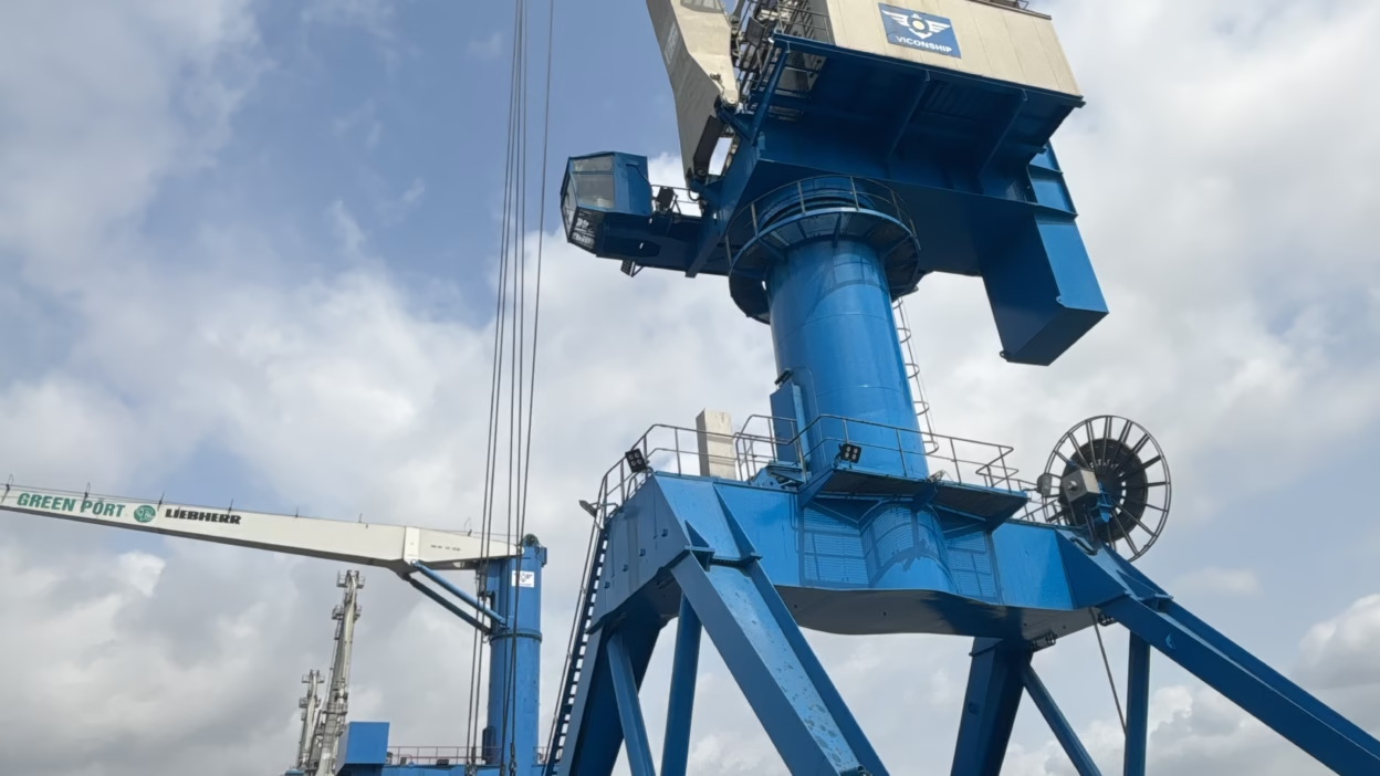
Modern container ports operate Ship-to-Shore (STS) cranes and massive gantry systems that demand unprecedented electrical power delivery. A typical STS trolley requires 18 kV to 30 kV of main power to lift 65-ton containers at speeds exceeding 600 meters per minute. This power must flow through a festoon cable system—a continuous loop of cable that unwinds and rewinds thousands of times per day as the trolley travels back and forth along the boom. Traditional round cables cannot solve this problem efficiently. A round medium voltage cable, rated for 18/30 kV, becomes rigid and difficult to bend. It occupies excessive space in the festoon track, requiring long parking lengths and increasing the footprint of the crane's electrical infrastructure. By contrast, a flat cable lays its massive phase cores side-by-side in a single plane, allowing for an incredibly tight bending radius—sometimes as small as 10 to 15 centimeters—while maintaining full electrical power delivery. This single geometric advantage reduces festoon track length by up to 40 percent, enabling faster crane acceleration and dramatically improving container terminal throughput.

RHEYFIRM®(RS)-FLAT (N)TSFLCGCWOEUS DIN VDE 0250 Medium Voltage Flat Festoon Cable: Premium Power Delivery for Ship-to-Shore Crane Trolleys, Heavy Gantry Systems, and High-Speed Container Port Automation

Modern container ports operate Ship-to-Shore (STS) cranes and massive gantry systems that demand unprecedented electrical power delivery. A typical STS trolley requires 18 kV to 30 kV of main power to lift 65-ton containers at speeds exceeding 600 meters per minute. This power must flow through a festoon cable system—a continuous loop of cable that unwinds and rewinds thousands of times per day as the trolley travels back and forth along the boom. Traditional round cables cannot solve this problem efficiently. A round medium voltage cable, rated for 18/30 kV, becomes rigid and difficult to bend. It occupies excessive space in the festoon track, requiring long parking lengths and increasing the footprint of the crane’s electrical infrastructure. By contrast, a flat cable lays its massive phase cores side-by-side in a single plane, allowing for an incredibly tight bending radius—sometimes as small as 10 to 15 centimeters—while maintaining full electrical power delivery. This single geometric advantage reduces festoon track length by up to 40 percent, enabling faster crane acceleration and dramatically improving container terminal throughput.
Manufacturer's technical guide: PROTOLON (SB) NTSCGEWOEU-LED, FeiChun's VDE 0250-813 and MSHA P-189-4 certified MV trailing cable with integrated self-powered LED illumination rated for −50 °C. Split earth three-core design. SHD-GC type. Shovel visibility. Dragline tail-rope illumination. Zero external DC supply. Direct factory manufacturer.

TENAX-CORD (RTS) NSHTOEU-LED 0,6/1 kV: Self-Powered LED Spreader Reeling Cable for High-Speed Container Crane Systems

TENAX-CORD (RTS) NSHTOEU-LED | 0,6/1 kV | FC-TPU™ P-Series Translucent Sheath | 7 Constructions 36×2.5–72×2.5 mm | Up to 3,300 A (44×2.5 core) | Port, Container Terminal, Automated Handling Applications | 240 m/min Vertical Reeling Speed
Manufacturer's technical guide: PROTOLON (SB) NTSCGEWOEU-LED, FeiChun's VDE 0250-813 and MSHA P-189-4 certified MV trailing cable with integrated self-powered LED illumination rated for −50 °C. Split earth three-core design. SHD-GC type. Shovel visibility. Dragline tail-rope illumination. Zero external DC supply. Direct factory manufacturer.

PROTOLON (SB) NTSCGEWOEU-LED 1,8/3 kV — FeiChun® Self-Powered LED Illuminated MV Trailing Cable for Electric Rope Shovels & Draglines: The Complete VDE 0250-813 & MSHA Guide

Manufacturer’s technical guide: PROTOLON (SB) NTSCGEWOEU-LED, FeiChun’s VDE 0250-813 and MSHA P-189-4 certified MV trailing cable with integrated self-powered LED illumination rated for −50 °C. Split earth three-core design. SHD-GC type. Shovel visibility. Dragline tail-rope illumination. Zero external DC supply. Direct factory manufacturer.
Manufacturer's technical guide: PROTOLON (FL) NTSFLCGEWOEU-LED — the world's first LED-illuminated MV flat reeling cable certified to DIN VDE 0250-813. FC-EMH™ harvests energy from the cable's own MV field at ≥3.6 kV — no inverter, no external wiring, no switchgear changes. Glows warning red when energised. Dark when isolated. Plug-and-play drop-in for any standard PROTOLON (FL) installation. 50,000+ reeling cycle sheath life. Zero maintenance LED system. Direct factory manufacturer.

PROTOLON (FL) NTSFLCGEWOEU-LED — FeiChun® Self-Powered LED Medium Voltage Flat Reeling Cable: The Complete VDE 0250-813 Guide for Container Cranes & Mining

Manufacturer’s technical guide: PROTOLON (FL) NTSFLCGEWOEU-LED — the world’s first LED-illuminated MV flat reeling cable certified to DIN VDE 0250-813. FC-EMH™ harvests energy from the cable’s own MV field at ≥3.6 kV — no inverter, no external wiring, no switchgear changes. Glows warning red when energised. Dark when isolated. Plug-and-play drop-in for any standard PROTOLON (FL) installation. 50,000+ reeling cycle sheath life. Zero maintenance LED system. Direct factory manufacturer.
(N)TSCGH3S-LED 6/10 kV — the VDE 0250-813 luminescent trailing cable for high-voltage electric rope shovels and draglines. Rated 6/10 kV, tested at 17 kV. FC-EMH™ harvests energy from the 10 kV field — no inverter, no external wiring. FC-LED™ strips in outer interstices replace EL phosphor wire. Glows red when energised. Dark when isolated. Zero maintenance. Direct factory manufacturer.

(N)TSCGH3S-LED 6/10 kV 

(N)TSCGH3S-LED 6/10 kV — the VDE 0250-813 luminescent trailing cable for high-voltage electric rope shovels and draglines. Rated 6/10 kV, tested at 17 kV. FC-EMH™ harvests energy from the 10 kV field — no inverter, no external wiring. FC-LED™ strips in outer interstices replace EL phosphor wire. Glows red when energised. Dark when isolated. Zero maintenance. Direct factory manufacturer.
(N)TSCGEWOEU-LED is a 3.6/6 (7.2) kV illuminated MV trailing cable for shovels and draglines, based on DIN VDE 0250-813, with GOST-R certification, Class 5 tinned copper conductors, EPR insulation, FC-EMH™ self-powered LED harvesting, FC-ASB™ stress-relief braid, and a translucent FR-TPU FC-TPU™ X-Series sheath formulated for flexibility down to −50 °C.

(N)TSCGEWOEU-LED 3.6/6 kV: A Self-Powered Illuminated Trailing Cable for Shovels, Draglines, and Extreme-Cold Open-Pit Mining Operations

(N)TSCGEWOEU-LED is a 3.6/6 (7.2) kV illuminated MV trailing cable for shovels and draglines, based on DIN VDE 0250-813, with GOST-R certification, Class 5 tinned copper conductors, EPR insulation, FC-EMH™ self-powered LED harvesting, FC-ASB™ stress-relief braid, and a translucent FR-TPU FC-TPU™ X-Series sheath formulated for flexibility down to −50 °C.
Complete Technical Guide to Specialized Vertical Reeling Cable Systems for Container Spreaders on Ship-to-Shore (STS) and Rubber-Tired Gantry (RTG) Cranes. Deep Analysis of Aramid (Kevlar) Core Strain-Relief Engineering, Gravity Suspension Load Physics, Dynamic Tension Management, Multi-Core Control Cable Architecture (24G2.5 through 48G2.5), Twist-Lock Sensor Integration, Flipper Control Circuits, High-Definition Camera Feed Transmission. VDE 0250-814 Standards, Vertical Reeling System Physics, Acceleration/Deceleration Shock Analysis, Material Selection (Rubber vs. Polyurethane), Real-World Deployment Scenarios, and Factory-Direct Procurement Strategy for Spreader Cable Replacement in High-Utilization Port Terminals.

Spreader Cable Reel Engineering Guide: Vertical Reeling Systems, Aramid Core Strain Relief, and Gravity Stress Management for Modern STS and RTG Container Cranes

Complete Technical Guide to Specialized Vertical Reeling Cable Systems for Container Spreaders on Ship-to-Shore (STS) and Rubber-Tired Gantry (RTG) Cranes. Deep Analysis of Aramid (Kevlar) Core Strain-Relief Engineering, Gravity Suspension Load Physics, Dynamic Tension Management, Multi-Core Control Cable Architecture (24G2.5 through 48G2.5), Twist-Lock Sensor Integration, Flipper Control Circuits, High-Definition Camera Feed Transmission. VDE 0250-814 Standards, Vertical Reeling System Physics, Acceleration/Deceleration Shock Analysis, Material Selection (Rubber vs. Polyurethane), Real-World Deployment Scenarios, and Factory-Direct Procurement Strategy for Spreader Cable Replacement in High-Utilization Port Terminals.
A comprehensive engineering guide for procurement managers, maintenance engineers, and electrification project leads who need to replace Prysmian/Draka PROTOMONT-branded reeling, festoon, and vertical hoist cables on port cranes and heavy industrial equipment. This document provides a complete cross-reference matrix mapping every PROTOMONT trade name to its underlying VDE (Verband der Elektrotechnik) standard designation, identifies the exact FeiChun drop-in equivalent for each variant, and specifies the critical installation and commissioning rules — including the No-Twist Spooling Rule, the Slip-Clutch Tension Limit (max 15 N/mm²), and the Multi-Layer Derating Factor — that must be enforced to prevent premature cable failure. Coverage spans low-voltage reeling cables per DIN VDE 0250-814, medium-voltage reeling cables per DIN VDE 0250-813, round and flat festoon cables, vertical hoist cables with Aramid-core reinforcement, and the specialised rubber compounds (5GM5 Neoprene, 3GI3 EPR) that determine the thermal and mechanical service life of each cable type.

PROTOMONT Crane Cable Replacement: Complete Technical Guide — Prysmian to FeiChun Cross-Reference, VDE 0250-814 / 0250-813 Compliance, and Reeling Installation Engineering for STS, RTG, RMG & Mining Applications

A comprehensive engineering guide for procurement managers, maintenance engineers, and electrification project leads who need to replace Prysmian/Draka PROTOMONT-branded reeling, festoon, and vertical hoist cables on port cranes and heavy industrial equipment. This document provides a complete cross-reference matrix mapping every PROTOMONT trade name to its underlying VDE (Verband der Elektrotechnik) standard designation, identifies the exact FeiChun drop-in equivalent for each variant, and specifies the critical installation and commissioning rules — including the No-Twist Spooling Rule, the Slip-Clutch Tension Limit (max 15 N/mm²), and the Multi-Layer Derating Factor — that must be enforced to prevent premature cable failure. Coverage spans low-voltage reeling cables per DIN VDE 0250-814, medium-voltage reeling cables per DIN VDE 0250-813, round and flat festoon cables, vertical hoist cables with Aramid-core reinforcement, and the specialised rubber compounds (5GM5 Neoprene, 3GI3 EPR) that determine the thermal and mechanical service life of each cable type.
Complete technical analysis of Prysmian CORDAFLEX SMK-V 0.6/1 kV low-voltage vertical reeling cable for STS cranes, spreader bar systems, container handlers: central Kevlar aramid core absorbs 20+ kN tensile load preventing copper core elongation under gravity, anti-torsion polyester braid prevents helical collapse during 240 m/min vertical operation, yellow neoprene PROTOFIRM sheath resists marine UV/ozone/salt-spray, Class FS tinned copper conductors maintain flexibility at -35°C. FeiChun NSHTOU-V — VDE 0250-814 certified direct equivalent with triple-extrusion process, 30–35% cost savings, 45–60 day lead time. Replaces CORDAFLEX SMK-V for global port terminals under import-substitution programs without equipment recalibration.

CORDAFLEX SMK-V Vertical Reeling Cable Replacement: Complete Engineering Analysis and Drop-In Solution for High-Speed STS Crane Spreader Hoists, Container Handlers, and Port Electrification Systems

Complete technical analysis of Prysmian CORDAFLEX SMK-V 0.6/1 kV low-voltage vertical reeling cable for STS cranes, spreader bar systems, container handlers: central Kevlar aramid core absorbs 20+ kN tensile load preventing copper core elongation under gravity, anti-torsion polyester braid prevents helical collapse during 240 m/min vertical operation, yellow neoprene PROTOFIRM sheath resists marine UV/ozone/salt-spray, Class FS tinned copper conductors maintain flexibility at -35°C. FeiChun NSHTOU-V — VDE 0250-814 certified direct equivalent with triple-extrusion process, 30–35% cost savings, 45–60 day lead time. Replaces CORDAFLEX SMK-V for global port terminals under import-substitution programs without equipment recalibration.
VDE Naming Scheme Breakdown—(N)TSFLCGEWÖU Structure: German DIN VDE 0298 cable designation uses a strictly defined letter code: (1) (N) = Nominal voltage 0.6–6 kV range (parentheses indicate optional designation, present only for medium-voltage cables), (2) T = Thermoplastic insulation (vs. R = rubber insulation), (3) S = Individual core screens present, (4) F = Flexible (Class 5 or 6 conductor stranding), (5) L = Oil-resistant sheath (vs. other designations), (6) C = PCP (polychloroprene, chloroprene rubber) sheath, (7) G = Multicore (bundled cores, vs. single-conductor), (8) E = Extra flame-retardant outer jacket, (9) WÖ = Special German designation indicating weather-resistant outer covering (Witterungsbeständig = weathering-resistant), (10) U = Unarmored construction. Result: (N)TSFLCGEWÖU = Medium-voltage flexible thermoplastic-insulated cable with individual core screens, oil-resistant + polychloroprene sheath, multicore, flame-retardant, weathering-resistant, unarmored. VDE命名体系严格按字母代码定义:(N)=0.6-6 kV额定电压(括号表可选)、T=热塑绝缘、S=独立芯屏蔽、F=柔性(Class 5/6导体)、L=耐油护套、C=PCP(聚氯橡胶)、G=多芯、E=特殊阻燃、WÖ=耐候性(Witterungsbeständig=防风化)、U=非铠装。整体意义:中压6 kV柔性热塑绝缘、多芯屏蔽、耐油+聚氯橡胶、阻燃、耐候、非铠装。

VDE Rubber Cracking at -50°C? Material Science Solution for (N)TSFLCGEWÖU 6kV Siberian Winter Deployment

VDE Naming Scheme Breakdown—(N)TSFLCGEWÖU Structure: German DIN VDE 0298 cable designation uses a strictly defined letter code: (1) (N) = Nominal voltage 0.6–6 kV range (parentheses indicate optional designation, present only for medium-voltage cables), (2) T = Thermoplastic insulation (vs. R = rubber insulation), (3) S = Individual core screens present, (4) F = Flexible (Class 5 or 6 conductor stranding), (5) L = Oil-resistant sheath (vs. other designations), (6) C = PCP (polychloroprene, chloroprene rubber) sheath, (7) G = Multicore (bundled cores, vs. single-conductor), (8) E = Extra flame-retardant outer jacket, (9) WÖ = Special German designation indicating weather-resistant outer covering (Witterungsbeständig = weathering-resistant), (10) U = Unarmored construction. Result: (N)TSFLCGEWÖU = Medium-voltage flexible thermoplastic-insulated cable with individual core screens, oil-resistant + polychloroprene sheath, multicore, flame-retardant, weathering-resistant, unarmored. VDE命名体系严格按字母代码定义:(N)=0.6-6 kV额定电压(括号表可选)、T=热塑绝缘、S=独立芯屏蔽、F=柔性(Class 5/6导体)、L=耐油护套、C=PCP(聚氯橡胶)、G=多芯、E=特殊阻燃、WÖ=耐候性(Witterungsbeständig=防风化)、U=非铠装。整体意义:中压6 kV柔性热塑绝缘、多芯屏蔽、耐油+聚氯橡胶、阻燃、耐候、非铠装。
The fundamental difference between mold-cured and continuous vulcanization processes lies in the physical pressure and thermal constraints applied to the rubber jacket during the cross-linking (vulcanization) phase. In continuous vulcanization, the extruded cable jacket enters a pressurized tube where steam or nitrogen provides only ambient fluid pressure (typically 20 to 100 psi), allowing microscopic air voids to persist within the rubber matrix—a manufacturing-efficient but mechanically compromising approach. In contrast, Nexans AmerCable's proprietary lead-mold curing process encloses the entire extruded cable within a continuous solid lead sheath that subjects the expanding rubber to extreme physical confinement pressure (1,000 to 3,000 psi or higher), forcing virtually all microscopic air voids out of the rubber and enabling optimal cross-linking of polymer chains. The resulting mold-cured jacket exhibits tensile strength 15 to 25 percent higher, tear resistance 20 to 40 percent superior, and abrasion resistance 25 to 50 percent greater than equivalent continuous vulcanization designs—advantages that justify the Tiger Brand's premium positioning and explain its dominant market share in high-altitude Chilean and Peruvian copper mining where cables endure continuous abrasion on jagged rocks, mechanical crushing from heavy loads, and environmental stress from sulfide ore compounds.

Mold-Cured Jacket: AmerCable Tiger Brand vs. Continuous Vulcanization – Why Is Mold-Cured Considered Tougher?

The fundamental difference between mold-cured and continuous vulcanization processes lies in the physical pressure and thermal constraints applied to the rubber jacket during the cross-linking (vulcanization) phase. In continuous vulcanization, the extruded cable jacket enters a pressurized tube where steam or nitrogen provides only ambient fluid pressure (typically 20 to 100 psi), allowing microscopic air voids to persist within the rubber matrix—a manufacturing-efficient but mechanically compromising approach. In contrast, Nexans AmerCable’s proprietary lead-mold curing process encloses the entire extruded cable within a continuous solid lead sheath that subjects the expanding rubber to extreme physical confinement pressure (1,000 to 3,000 psi or higher), forcing virtually all microscopic air voids out of the rubber and enabling optimal cross-linking of polymer chains. The resulting mold-cured jacket exhibits tensile strength 15 to 25 percent higher, tear resistance 20 to 40 percent superior, and abrasion resistance 25 to 50 percent greater than equivalent continuous vulcanization designs—advantages that justify the Tiger Brand’s premium positioning and explain its dominant market share in high-altitude Chilean and Peruvian copper mining where cables endure continuous abrasion on jagged rocks, mechanical crushing from heavy loads, and environmental stress from sulfide ore compounds.
RHEYFIRM® (XT) "Extreme" is a specialized arctic-grade flexible reeling cable engineered specifically for continuous dynamic operation in permafrost mining zones and open-pit operations where temperatures fall to -50°C (-58°F), whereas RHEYFIRM® (RS) standard versions are designed for conventional industrial and port environments operating down to approximately -25°C to -35°C maximum. The XT extreme variant differs from the RS standard version through four fundamental structural and chemical modifications. First, the outer jacket compound transitions from standard chlorinated rubber (5GM5 formulation) to an ultra-low-temperature advanced elastomer or specialized cold-resistant polyurethane (PUR) blend that remains flexible and resistant to crystallization and embrittlement even when exposed to -50°C arctic blasts. Second, the internal structure incorporates enhanced cold-adapted synthetic anti-torsion braids fabricated from Kevlar and Aramid fibers instead of conventional braid materials, which maintain their reinforcement properties at extreme temperatures where standard materials would lose rigidity. Third, the insulation material evolves from standard EPR (ethylene propylene rubber) to an optimized cold-flexible EPR formulation that prevents micro-cracking around copper conductors under severe thermal stress. Fourth, the cable incorporates specialized core lubrication systems and internal slip-layers designed to reduce friction between conductor wires at sub-zero temperatures, where natural friction increases dramatically and would otherwise cause internal conductor fatigue and snapping. The result is a cable system that remains mechanically robust and electrically reliable for continuous high-speed reeling (up to 190 meters per minute) on frozen ground and ice-covered surfaces in the harshest mining environments on Earth. The electrical specifications remain identical to RS standard cables (same voltage ratings, same current capacity), but the physical behavior and mechanical reliability at extreme cold are fundamentally different. You should specify RHEYFIRM® (XT) when your mining operation is located in permafrost regions, when winter operations regularly experience temperatures below -40°C, when continuous reeling stress is combined with sub-zero conditions, and when cable failure could result in equipment shutdown in a remote arctic location where emergency replacement is logistically impossible.

RHEYFIRM® (XT): How Does the “Extreme” Version Differ from Standard (RS) for Operations in -50°C Arctic Mines?

RHEYFIRM® (XT) “Extreme” is a specialized arctic-grade flexible reeling cable engineered specifically for continuous dynamic operation in permafrost mining zones and open-pit operations where temperatures fall to -50°C (-58°F), whereas RHEYFIRM® (RS) standard versions are designed for conventional industrial and port environments operating down to approximately -25°C to -35°C maximum. The XT extreme variant differs from the RS standard version through four fundamental structural and chemical modifications. First, the outer jacket compound transitions from standard chlorinated rubber (5GM5 formulation) to an ultra-low-temperature advanced elastomer or specialized cold-resistant polyurethane (PUR) blend that remains flexible and resistant to crystallization and embrittlement even when exposed to -50°C arctic blasts. Second, the internal structure incorporates enhanced cold-adapted synthetic anti-torsion braids fabricated from Kevlar and Aramid fibers instead of conventional braid materials, which maintain their reinforcement properties at extreme temperatures where standard materials would lose rigidity. Third, the insulation material evolves from standard EPR (ethylene propylene rubber) to an optimized cold-flexible EPR formulation that prevents micro-cracking around copper conductors under severe thermal stress. Fourth, the cable incorporates specialized core lubrication systems and internal slip-layers designed to reduce friction between conductor wires at sub-zero temperatures, where natural friction increases dramatically and would otherwise cause internal conductor fatigue and snapping. The result is a cable system that remains mechanically robust and electrically reliable for continuous high-speed reeling (up to 190 meters per minute) on frozen ground and ice-covered surfaces in the harshest mining environments on Earth. The electrical specifications remain identical to RS standard cables (same voltage ratings, same current capacity), but the physical behavior and mechanical reliability at extreme cold are fundamentally different. You should specify RHEYFIRM® (XT) when your mining operation is located in permafrost regions, when winter operations regularly experience temperatures below -40°C, when continuous reeling stress is combined with sub-zero conditions, and when cable failure could result in equipment shutdown in a remote arctic location where emergency replacement is logistically impossible.
RHEYFIRM® is Nexans' premium line of flexible medium-voltage reeling cables specifically engineered for the extreme mechanical and environmental stresses of port machinery (STS cranes, automated stacker-reclaimers) and mining equipment (continuous dragline cables, mobile crusher power systems). Unlike fixed installation cables that remain stationary throughout their service life, reeling cables experience constant dynamic stress—deploying and retracting hundreds to thousands of times over their operational life. This continuous reeling duty subjects the cable to millions of bending cycles, sustained tensile loads, electromagnetic stress, salt spray corrosion, intense ultraviolet radiation, and temperature extremes far exceeding what conventional industrial cables are designed to tolerate. The physical diameter of a reeling cable is not simply a matter of aesthetics or standardization—it directly affects how much cable can fit on a physical drum of fixed dimensions. Consider a stacker-reclaimer with an existing cable drum that has a fixed flange width (say, 1,200 millimeters) and a fixed core diameter (say, 400 millimeters). The amount of cable that can be wound onto this drum depends on how tightly the cable packs around the core. A cable with a 59-millimeter outer diameter will create a larger spiral as it is wound layer by layer, limiting the total cable length to perhaps 600 meters. That same physical drum, if fitted with a 55.8-millimeter diameter cable, creates a tighter spiral and accommodates perhaps 750 meters of cable—a 25 percent increase in usable length with zero change to the physical equipment. For equipment where travel distance requirements have increased due to terminal expansion or operational upgrades, this diameter optimization can mean the difference between being able to extend operations and being forced into an expensive drum replacement project costing hundreds of thousands of dollars.

RHEYFIRM® (RS) vs. RHEYFIRM® (RTS): When to Choose the “Reduced Diameter” Version for Space-Constrained Reels

RHEYFIRM® is Nexans’ premium line of flexible medium-voltage reeling cables specifically engineered for the extreme mechanical and environmental stresses of port machinery (STS cranes, automated stacker-reclaimers) and mining equipment (continuous dragline cables, mobile crusher power systems). Unlike fixed installation cables that remain stationary throughout their service life, reeling cables experience constant dynamic stress—deploying and retracting hundreds to thousands of times over their operational life. This continuous reeling duty subjects the cable to millions of bending cycles, sustained tensile loads, electromagnetic stress, salt spray corrosion, intense ultraviolet radiation, and temperature extremes far exceeding what conventional industrial cables are designed to tolerate. The physical diameter of a reeling cable is not simply a matter of aesthetics or standardization—it directly affects how much cable can fit on a physical drum of fixed dimensions. Consider a stacker-reclaimer with an existing cable drum that has a fixed flange width (say, 1,200 millimeters) and a fixed core diameter (say, 400 millimeters). The amount of cable that can be wound onto this drum depends on how tightly the cable packs around the core. A cable with a 59-millimeter outer diameter will create a larger spiral as it is wound layer by layer, limiting the total cable length to perhaps 600 meters. That same physical drum, if fitted with a 55.8-millimeter diameter cable, creates a tighter spiral and accommodates perhaps 750 meters of cable—a 25 percent increase in usable length with zero change to the physical equipment. For equipment where travel distance requirements have increased due to terminal expansion or operational upgrades, this diameter optimization can mean the difference between being able to extend operations and being forced into an expensive drum replacement project costing hundreds of thousands of dollars.
NSHTÖU-J 24G2.5 flexible reeling cable is the globally recognized industry standard for ship-to-shore crane spreader basket vertical lift systems, featuring 24 conductors with 2.5 mm² cross-section per core (one conductor designated green/yellow for grounding/safety) providing approximately 30 amperes current capacity in free-air installation at 30°C ambient, but derating to approximately 15 amperes actual safe continuous current when accounting for the multi-core bundle derating factor of 0.45 to 0.50 and tropical port ambient temperatures. The cable's nominal outer diameter ranges from 28.5 to 32.5 millimeters, with total weight of approximately 1,350 kilograms per kilometer, making it manageable for standard spreader basket spools while maintaining the conductor density necessary for reliable simultaneous power and control signal transmission. The cable features proprietary anti-torsion braid structure embedded between inner and outer sheaths—a critical innovation that provides resistance to ±50° per meter torsional deformation, fundamentally preventing the destructive corkscrew effect that kills ordinary flexible cables within 3 to 6 months of tropical port operation. The cable incorporates Class 5 tinned copper conductors engineered specifically for the fatigue resistance required by continuous 160 meters per minute reeling cycles, EPDM insulation maintaining electrical integrity at the 90°C conductor temperatures that result from high-speed duty cycles in multi-core bundles, 5GM5 elastomer outer sheath providing exceptional resistance to salt-spray corrosion, UV degradation, petroleum-based oils, and mechanical abrasion encountered in global container ports. The cable is rated for 0.6/1.0 kilovolt nominal operation, with dielectric test voltage capability reaching 3 kilovolts, more than adequate for spreader basket control circuits and auxiliary power distribution. Unlike generic "marine-grade" cables or rebranded industrial flexible cables, NSHTÖU-J 24G2.5 is purpose-built to tolerate the combined mechanical, thermal, and environmental stresses unique to STS crane spreader applications—making it not simply the preferred option but the only technically defensible choice for reliability-critical spreader systems operating in high-intensity container port environments.

STS Crane Spreader Baskets: Why NSHTÖU-J 24G2.5 is the Industry Standard for Vertical Lift Power & Control

NSHTÖU-J 24G2.5 flexible reeling cable is the globally recognized industry standard for ship-to-shore crane spreader basket vertical lift systems, featuring 24 conductors with 2.5 mm² cross-section per core (one conductor designated green/yellow for grounding/safety) providing approximately 30 amperes current capacity in free-air installation at 30°C ambient, but derating to approximately 15 amperes actual safe continuous current when accounting for the multi-core bundle derating factor of 0.45 to 0.50 and tropical port ambient temperatures. The cable’s nominal outer diameter ranges from 28.5 to 32.5 millimeters, with total weight of approximately 1,350 kilograms per kilometer, making it manageable for standard spreader basket spools while maintaining the conductor density necessary for reliable simultaneous power and control signal transmission. The cable features proprietary anti-torsion braid structure embedded between inner and outer sheaths—a critical innovation that provides resistance to ±50° per meter torsional deformation, fundamentally preventing the destructive corkscrew effect that kills ordinary flexible cables within 3 to 6 months of tropical port operation. The cable incorporates Class 5 tinned copper conductors engineered specifically for the fatigue resistance required by continuous 160 meters per minute reeling cycles, EPDM insulation maintaining electrical integrity at the 90°C conductor temperatures that result from high-speed duty cycles in multi-core bundles, 5GM5 elastomer outer sheath providing exceptional resistance to salt-spray corrosion, UV degradation, petroleum-based oils, and mechanical abrasion encountered in global container ports. The cable is rated for 0.6/1.0 kilovolt nominal operation, with dielectric test voltage capability reaching 3 kilovolts, more than adequate for spreader basket control circuits and auxiliary power distribution. Unlike generic “marine-grade” cables or rebranded industrial flexible cables, NSHTÖU-J 24G2.5 is purpose-built to tolerate the combined mechanical, thermal, and environmental stresses unique to STS crane spreader applications—making it not simply the preferred option but the only technically defensible choice for reliability-critical spreader systems operating in high-intensity container port environments.
(N)TSCGEWÖU 3x120+3x70/3 12/20kV cable is the correct choice for most tunnel boring machine main cutterhead power supplies operating at medium voltage with cutterhead thrust loads in the range of 8,000 to 12,000 kilonewtons, featuring three 120 mm² phase conductors providing approximately 350 to 380 amperes current capacity in free-air installation at 30°C ambient and 90°C conductor operating temperature. The cable's nominal outer diameter is 73 to 81 millimeters, with total weight of approximately 9,800 to 10,500 kilograms per kilometer, making it manageable for most standard cable spools while still providing sufficient conductor cross-section to limit voltage drop to acceptable levels over tunnel distances extending several kilometers. The cable features Class 5 tinned copper conductors engineered for fatigue resistance in continuously flexing applications, EPR insulation maintaining exceptional thermal stability even when subjected to the 90°C conductor temperature that results from high-current excavation duty, semi-conductive shielding layers that uniformly distribute electric stress and prevent partial discharge initiation in the high-voltage environment, and a heavy-duty CPE jacket providing abrasion resistance in the confined underground spaces where the cable is routed. However, the critical distinction between simply selecting a cable model and properly sizing a cable for your specific tunnel boring installation lies in understanding the difference between the cable's theoretical free-air current capacity and its actual safe operating current when coiled on a cable drum—a difference that can reduce safe current by 30 to 50 percent depending on the spooling configuration. For tunnel boring machines operating in continental European or Asian tunneling projects with tunnel lengths of 5 to 15 kilometers and cutterhead thrust loads in the moderate to high range, the 3x120+3x70/3 12/20kV cable provides excellent balance between current capacity, voltage drop performance, mechanical durability, and cost. However, for shorter tunnels where voltage drop is not a concern, smaller conductor sizes (such as 3x95 mm²) may provide adequate performance at lower material cost, while for exceptionally long tunnels or extremely high thrust conditions, larger sizes (such as 3x150 mm² or 3x185 mm²) become necessary to maintain safe operating currents and acceptable voltage drop. Proper cable sizing requires engineering analysis specific to your tunnel length, expected cutterhead current demand, acceptable voltage drop limits, available cable drum diameters, and operational duty cycle.

Tunnel Boring Machines (TBM): Sizing (N)TSCGEWÖU 3×120+3×70/3 12/20kV for the Main Cutterhead Power Supply

(N)TSCGEWÖU 3×120+3×70/3 12/20kV cable is the correct choice for most tunnel boring machine main cutterhead power supplies operating at medium voltage with cutterhead thrust loads in the range of 8,000 to 12,000 kilonewtons, featuring three 120 mm² phase conductors providing approximately 350 to 380 amperes current capacity in free-air installation at 30°C ambient and 90°C conductor operating temperature. The cable’s nominal outer diameter is 73 to 81 millimeters, with total weight of approximately 9,800 to 10,500 kilograms per kilometer, making it manageable for most standard cable spools while still providing sufficient conductor cross-section to limit voltage drop to acceptable levels over tunnel distances extending several kilometers. The cable features Class 5 tinned copper conductors engineered for fatigue resistance in continuously flexing applications, EPR insulation maintaining exceptional thermal stability even when subjected to the 90°C conductor temperature that results from high-current excavation duty, semi-conductive shielding layers that uniformly distribute electric stress and prevent partial discharge initiation in the high-voltage environment, and a heavy-duty CPE jacket providing abrasion resistance in the confined underground spaces where the cable is routed. However, the critical distinction between simply selecting a cable model and properly sizing a cable for your specific tunnel boring installation lies in understanding the difference between the cable’s theoretical free-air current capacity and its actual safe operating current when coiled on a cable drum—a difference that can reduce safe current by 30 to 50 percent depending on the spooling configuration. For tunnel boring machines operating in continental European or Asian tunneling projects with tunnel lengths of 5 to 15 kilometers and cutterhead thrust loads in the moderate to high range, the 3×120+3×70/3 12/20kV cable provides excellent balance between current capacity, voltage drop performance, mechanical durability, and cost. However, for shorter tunnels where voltage drop is not a concern, smaller conductor sizes (such as 3×95 mm²) may provide adequate performance at lower material cost, while for exceptionally long tunnels or extremely high thrust conditions, larger sizes (such as 3×150 mm² or 3×185 mm²) become necessary to maintain safe operating currents and acceptable voltage drop. Proper cable sizing requires engineering analysis specific to your tunnel length, expected cutterhead current demand, acceptable voltage drop limits, available cable drum diameters, and operational duty cycle.
The Type W 4/C 2/0 AWG 2000V cable features a heavy-duty thermoset CPE (chlorinated polyethylene) jacket that is specifically formulated with UV stabilizers and ozone-resistant additives, providing robust protection against continuous direct sunlight and high ozone concentrations found in desert port environments. The cable is rated to withstand prolonged outdoor exposure in desert conditions, typically maintaining 80 to 90 percent of its physical properties after 5 to 10 years of continuous unshaded sunlight exposure, compared to standard elastomeric jackets that degrade to 50 to 70 percent property retention under identical conditions. The nominal outer diameter of this cable is 46.8 to 49.1 mm (1.845 to 1.935 inches), with approximate weight of 4,390 to 5,133 kg per kilometer. The cable features 259-strand rope-lay copper conductors (2/0 AWG per core), four 67.4 mm² cores, EPDM insulation rated for 90°C conductor temperature, and current carrying capacity of 237 amperes (based on 30°C ambient, 90°C conductor temperature). However, the critical distinction that separates viable long-term desert service from premature field failures lies in understanding the difference between a cable jacket that merely resists UV degradation and a comprehensively designed system where all exposed components—including terminal connections, stripped insulation, and mechanical attachment points—receive appropriate protection from direct sunlight. In actual desert port applications, failures are as frequently caused by UV damage at unprotected termination points as by jacket degradation itself, making installation and maintenance procedures as important as material selection. For typical desert port power systems, RTG (rubber-tired gantry) crane power leads, shore-to-ship power cables, and fixed deck-mounted power distribution systems operating in Middle Eastern, North African, and Australian port environments, the Type W 4/C 2/0 AWG cable with standard CPE jacket provides reliable field-proven performance when properly installed and maintained, but premium UV-resistant cable variants should be considered for applications where service life extension beyond 7 to 10 years is critical or where inspection and maintenance infrastructure is limited.

UV & Ozone Resistance of Type W 4/C 2/0 AWG 2000V: Is the CPE Jacket Durable Enough for Constant Direct Sunlight in Desert Ports?

The Type W 4/C 2/0 AWG 2000V cable features a heavy-duty thermoset CPE (chlorinated polyethylene) jacket that is specifically formulated with UV stabilizers and ozone-resistant additives, providing robust protection against continuous direct sunlight and high ozone concentrations found in desert port environments. The cable is rated to withstand prolonged outdoor exposure in desert conditions, typically maintaining 80 to 90 percent of its physical properties after 5 to 10 years of continuous unshaded sunlight exposure, compared to standard elastomeric jackets that degrade to 50 to 70 percent property retention under identical conditions. The nominal outer diameter of this cable is 46.8 to 49.1 mm (1.845 to 1.935 inches), with approximate weight of 4,390 to 5,133 kg per kilometer. The cable features 259-strand rope-lay copper conductors (2/0 AWG per core), four 67.4 mm² cores, EPDM insulation rated for 90°C conductor temperature, and current carrying capacity of 237 amperes (based on 30°C ambient, 90°C conductor temperature). However, the critical distinction that separates viable long-term desert service from premature field failures lies in understanding the difference between a cable jacket that merely resists UV degradation and a comprehensively designed system where all exposed components—including terminal connections, stripped insulation, and mechanical attachment points—receive appropriate protection from direct sunlight. In actual desert port applications, failures are as frequently caused by UV damage at unprotected termination points as by jacket degradation itself, making installation and maintenance procedures as important as material selection. For typical desert port power systems, RTG (rubber-tired gantry) crane power leads, shore-to-ship power cables, and fixed deck-mounted power distribution systems operating in Middle Eastern, North African, and Australian port environments, the Type W 4/C 2/0 AWG cable with standard CPE jacket provides reliable field-proven performance when properly installed and maintained, but premium UV-resistant cable variants should be considered for applications where service life extension beyond 7 to 10 years is critical or where inspection and maintenance infrastructure is limited.
Type SHD-GC 3/C 4/0 AWG 8kV trailing cable, rated for 321 to 327 amperes continuous current at sea level (0 meters) assuming typical mining conditions with natural air cooling, experiences substantial reduction in current-carrying capacity when deployed at 4,000 meters elevation in the Andes Mountains. At 4,000 meters, the atmospheric pressure is only approximately 60 percent of sea-level pressure, and air density is reduced proportionally. This thin-air environment reduces the cable's cooling efficiency dramatically, resulting in derated ampacity of approximately 185 to 210 amperes—a reduction of 40 to 45 percent compared to sea-level capacity. This derating is not optional or conservative—it is physically necessary to prevent the cable conductor from exceeding the maximum allowable operating temperature of 90°C under continuous load. If a cable rated at 321A at sea level were operated at full sea-level ampacity while installed at 4,000 meters elevation, the conductor temperature would rise to approximately 120°C to 140°C or higher, severely accelerating insulation degradation and risking catastrophic failure within months. The derating magnitude is driven by fundamental thermodynamic principles: as altitude increases and air density decreases, the convective heat transfer coefficient that governs how efficiently the cable surface transfers heat to the surrounding air decreases proportionally. The relationship between air density and cooling efficiency is not linear—it follows approximately the 0.6 power relationship, meaning that reducing air density to 60 percent of sea-level value reduces cooling efficiency to approximately 70 percent. Additionally, in high-altitude Andes mining regions where ambient temperatures reach 25°C to 35°C in tropical regions or 40°C to 50°C in equipment enclosures, the combined effect of altitude derating plus temperature derating can reduce ampacity to values as low as 150 to 160 amperes—less than half the sea-level rating. Understanding and properly accounting for altitude derating in equipment selection, protection device settings, and operational procedures is essential for safe and reliable operation of power distribution systems at high-altitude mining facilities.

High-Altitude Ampacity Derating: How Does Operating at 4,000m in the Andes Mountains Affect Type SHD-GC 3/C 4/0 AWG 8kV Cable Current Capacity?

Type SHD-GC 3/C 4/0 AWG 8kV trailing cable, rated for 321 to 327 amperes continuous current at sea level (0 meters) assuming typical mining conditions with natural air cooling, experiences substantial reduction in current-carrying capacity when deployed at 4,000 meters elevation in the Andes Mountains. At 4,000 meters, the atmospheric pressure is only approximately 60 percent of sea-level pressure, and air density is reduced proportionally. This thin-air environment reduces the cable’s cooling efficiency dramatically, resulting in derated ampacity of approximately 185 to 210 amperes—a reduction of 40 to 45 percent compared to sea-level capacity. This derating is not optional or conservative—it is physically necessary to prevent the cable conductor from exceeding the maximum allowable operating temperature of 90°C under continuous load. If a cable rated at 321A at sea level were operated at full sea-level ampacity while installed at 4,000 meters elevation, the conductor temperature would rise to approximately 120°C to 140°C or higher, severely accelerating insulation degradation and risking catastrophic failure within months. The derating magnitude is driven by fundamental thermodynamic principles: as altitude increases and air density decreases, the convective heat transfer coefficient that governs how efficiently the cable surface transfers heat to the surrounding air decreases proportionally. The relationship between air density and cooling efficiency is not linear—it follows approximately the 0.6 power relationship, meaning that reducing air density to 60 percent of sea-level value reduces cooling efficiency to approximately 70 percent. Additionally, in high-altitude Andes mining regions where ambient temperatures reach 25°C to 35°C in tropical regions or 40°C to 50°C in equipment enclosures, the combined effect of altitude derating plus temperature derating can reduce ampacity to values as low as 150 to 160 amperes—less than half the sea-level rating. Understanding and properly accounting for altitude derating in equipment selection, protection device settings, and operational procedures is essential for safe and reliable operation of power distribution systems at high-altitude mining facilities.
For cables deployed in the extreme radiant heat environment near steel mill slag transfer cars, where surface temperatures frequently reach 120°C to 150°C and occasionally exceed 160°C, the LAPP ÖLFLEX HEAT 180 silicone cable is substantially better suited than the standard (N)GRXGöu rubber cable, provided appropriate thermal monitoring and distance spacing are maintained. The LAPP ÖLFLEX HEAT 180, with its continuous operating temperature rating of 180°C (short-term to 200°C), provides a practical safety margin that allows reliable operation even when cable surface temperatures approach 150°C, whereas the (N)GRXGöu, rated for 90°C continuous operation (or 120°C for specialized high-temperature variants), begins to experience unacceptable material degradation at surface temperatures above 100°C to 110°C. However, the critical distinction that engineers often overlook is that a cable rated for 180°C continuous operation is not automatically safe when placed near a radiant heat source at 150°C surface temperature. The actual service life and reliability depend on multiple factors beyond the simple temperature comparison: the duration of exposure, whether the radiant heat exposure is continuous or intermittent, thermal cycling between high and low temperatures, the specific material composition and thermal cycling resistance of the insulation, cable routing distance from the heat source, and implementation of heat shielding or protective conduit. In actual steel mill deployments at integrated steelworks and open-hearth facilities, cables properly routed with 1 to 2 meters clearance from slag cars and protected with ceramic or reflective heat shielding can achieve 3 to 5 years of reliable service using LAPP ÖLFLEX HEAT 180, compared to approximately 6 to 12 months of acceptable service for standard (N)GRXGöu in the same thermal environment. The premium cost of LAPP ÖLFLEX HEAT 180—typically 40 to 60 percent higher than standard (N)GRXGöu—is economically justified in steel mill applications primarily because the extended service life and reduced replacement frequency far outweigh the higher initial cable cost, and secondarily because unplanned cable failures in integrated steelworks can cause production shutdowns costing tens of thousands of euros per hour.

High-Temperature Cable Selection: Can (N)GRXGöu or LAPP ÖLFLEX HEAT 180 Survive Radiant Heat Near Steel Mill Slag Transfer Cars?

For cables deployed in the extreme radiant heat environment near steel mill slag transfer cars, where surface temperatures frequently reach 120°C to 150°C and occasionally exceed 160°C, the LAPP ÖLFLEX HEAT 180 silicone cable is substantially better suited than the standard (N)GRXGöu rubber cable, provided appropriate thermal monitoring and distance spacing are maintained. The LAPP ÖLFLEX HEAT 180, with its continuous operating temperature rating of 180°C (short-term to 200°C), provides a practical safety margin that allows reliable operation even when cable surface temperatures approach 150°C, whereas the (N)GRXGöu, rated for 90°C continuous operation (or 120°C for specialized high-temperature variants), begins to experience unacceptable material degradation at surface temperatures above 100°C to 110°C. However, the critical distinction that engineers often overlook is that a cable rated for 180°C continuous operation is not automatically safe when placed near a radiant heat source at 150°C surface temperature. The actual service life and reliability depend on multiple factors beyond the simple temperature comparison: the duration of exposure, whether the radiant heat exposure is continuous or intermittent, thermal cycling between high and low temperatures, the specific material composition and thermal cycling resistance of the insulation, cable routing distance from the heat source, and implementation of heat shielding or protective conduit. In actual steel mill deployments at integrated steelworks and open-hearth facilities, cables properly routed with 1 to 2 meters clearance from slag cars and protected with ceramic or reflective heat shielding can achieve 3 to 5 years of reliable service using LAPP ÖLFLEX HEAT 180, compared to approximately 6 to 12 months of acceptable service for standard (N)GRXGöu in the same thermal environment. The premium cost of LAPP ÖLFLEX HEAT 180—typically 40 to 60 percent higher than standard (N)GRXGöu—is economically justified in steel mill applications primarily because the extended service life and reduced replacement frequency far outweigh the higher initial cable cost, and secondarily because unplanned cable failures in integrated steelworks can cause production shutdowns costing tens of thousands of euros per hour.
The NSSHÖU-J 4G95 0.6/1kV industrial mining cable is technically rated for temporary water immersion and is commonly used in open-pit and underground mining environments, but it is not specifically qualified for permanent submersion in acidic mine water and using it in this application is classified as beyond its design envelope. While the cable's EPR insulation (3GI3) and CPE outer sheath (5GM5) provide adequate resistance to neutral water and brief acidic exposure, permanent submersion in acidic mine water with pH values of 2.0 to 4.0—typical of copper and gold mining operations—accelerates material degradation to the point where service life drops to approximately 18 to 36 months compared to 8 to 10 years in neutral water applications. The fundamental issue is not that the cable fails immediately when deployed in acidic water (it does not), but rather that the aggressive acidic environment causes progressive swelling of the jacket, penetration of H⁺ ions into the insulation layer, electrochemical corrosion of the tinned copper conductor, and cumulative electrical property loss that eventually results in insulation breakdown. This distinction between "survives temporary exposure" and "safe for permanent submersion" is critically important to understand: a cable can physically remain intact for months or even a year or more in acidic water, but the electrical properties are degrading silently, and catastrophic failure can occur suddenly when the insulation resistance drops below critical thresholds. For submersible pump applications in acidic mine water, engineers should specify cables explicitly designed for this service, such as H07RN8-F submersible pump cables with specialized halogen-free formulations, or upgrade to acidic-resistant variants of marine-grade cables rated for chemical exposure. The standard NSSHÖU-J cable can be used in acidic mine water applications only if the operational requirement is for temporary or seasonal service (less than 6 months per year), coupled with rigorous monitoring protocols and planned replacement intervals of 12 to 18 months rather than the standard 5 to 7 year intervals appropriate for neutral water service.

Submersible Pump Cable Safety: Can NSSHÖU-J 4G95 0.6/1kV Withstand Permanent Submersion in Acidic Mine Water?

The NSSHÖU-J 4G95 0.6/1kV industrial mining cable is technically rated for temporary water immersion and is commonly used in open-pit and underground mining environments, but it is not specifically qualified for permanent submersion in acidic mine water and using it in this application is classified as beyond its design envelope. While the cable’s EPR insulation (3GI3) and CPE outer sheath (5GM5) provide adequate resistance to neutral water and brief acidic exposure, permanent submersion in acidic mine water with pH values of 2.0 to 4.0—typical of copper and gold mining operations—accelerates material degradation to the point where service life drops to approximately 18 to 36 months compared to 8 to 10 years in neutral water applications. The fundamental issue is not that the cable fails immediately when deployed in acidic water (it does not), but rather that the aggressive acidic environment causes progressive swelling of the jacket, penetration of H⁺ ions into the insulation layer, electrochemical corrosion of the tinned copper conductor, and cumulative electrical property loss that eventually results in insulation breakdown. This distinction between “survives temporary exposure” and “safe for permanent submersion” is critically important to understand: a cable can physically remain intact for months or even a year or more in acidic water, but the electrical properties are degrading silently, and catastrophic failure can occur suddenly when the insulation resistance drops below critical thresholds. For submersible pump applications in acidic mine water, engineers should specify cables explicitly designed for this service, such as H07RN8-F submersible pump cables with specialized halogen-free formulations, or upgrade to acidic-resistant variants of marine-grade cables rated for chemical exposure. The standard NSSHÖU-J cable can be used in acidic mine water applications only if the operational requirement is for temporary or seasonal service (less than 6 months per year), coupled with rigorous monitoring protocols and planned replacement intervals of 12 to 18 months rather than the standard 5 to 7 year intervals appropriate for neutral water service.
The standard (N)TSCGEWÖU 3x50+3x25/3 trailing cable is technically rated for ambient temperatures down to approximately -10°C to -15°C under normal industrial conditions according to DIN VDE 0250 Part 813, with the 5GM5 CPE (chlorinated polyethylene) rubber jacket remaining flexible and maintaining mechanical integrity within this range. However, operating this cable in Arctic mining environments at sustained -40°C temperatures requires significant engineering reevaluation and is not recommended without specialized modifications and enhanced installation protocols. While the cable does not spontaneously fail at -40°C, the rubber jacket becomes progressively more rigid and brittle, and the minimum allowable bending radius must be expanded from the standard 15D (15 times the outer diameter) to approximately 25D to 30D or greater to prevent jacket cracking during dynamic reeling operations. At -50°C, which occurs frequently in Siberia and parts of Northern Canada during winter, standard TECWATER-family cables experience material brittleness that pushes them toward structural failure risk even without bending stress. A cable suitable for -15°C temperate mining operations is fundamentally different in its application safety profile from a cable operating continuously at -40°C in an open-pit mine where the cable must flex regularly during equipment deployment and retrieval. The distinction between "technically possible" and "operationally safe" is critical to understand: equipment that operates at extreme cold requires more than just survival—it requires predictable, controlled behavior under stress. The standard (N)TSCGEWÖU can survive brief exposure to -40°C without immediate failure, but extended service in this temperature regime demands either specification of cold-hardened alternatives or acceptance of significant operational constraints.

Arctic Mining Cable Performance: Is (N)TSCGEWÖU 3×50+3×25/3 Rated for -40°C Extreme Cold Conditions in Russia and Canada?

The standard (N)TSCGEWÖU 3×50+3×25/3 trailing cable is technically rated for ambient temperatures down to approximately -10°C to -15°C under normal industrial conditions according to DIN VDE 0250 Part 813, with the 5GM5 CPE (chlorinated polyethylene) rubber jacket remaining flexible and maintaining mechanical integrity within this range. However, operating this cable in Arctic mining environments at sustained -40°C temperatures requires significant engineering reevaluation and is not recommended without specialized modifications and enhanced installation protocols. While the cable does not spontaneously fail at -40°C, the rubber jacket becomes progressively more rigid and brittle, and the minimum allowable bending radius must be expanded from the standard 15D (15 times the outer diameter) to approximately 25D to 30D or greater to prevent jacket cracking during dynamic reeling operations. At -50°C, which occurs frequently in Siberia and parts of Northern Canada during winter, standard TECWATER-family cables experience material brittleness that pushes them toward structural failure risk even without bending stress. A cable suitable for -15°C temperate mining operations is fundamentally different in its application safety profile from a cable operating continuously at -40°C in an open-pit mine where the cable must flex regularly during equipment deployment and retrieval. The distinction between “technically possible” and “operationally safe” is critical to understand: equipment that operates at extreme cold requires more than just survival—it requires predictable, controlled behavior under stress. The standard (N)TSCGEWÖU can survive brief exposure to -40°C without immediate failure, but extended service in this temperature regime demands either specification of cold-hardened alternatives or acceptance of significant operational constraints.
Prysmian TECWATER 3x120 mm² submersible pump cable has a standardized maximum operating depth of approximately 10 meters under the VDE certification standard (DIN VDE 0298-300) in typical industrial environments. This 10-meter specification assumes normal freshwater conditions, moderate water quality without unusual corrosive properties, and water temperature not exceeding 40°C. However, in extended applications involving less corrosive water sources (such as industrial cooling water circuits, mining surface drainage, or rainwater collection systems) where inspection and maintenance requirements are relaxed, the cable can operate at depths up to 500 meters, provided all mechanical stresses are carefully managed and the cable is protected from snapping or mechanical damage during deployment. The relationship between depth and service life is non-linear and governed by hydrostatic pressure physics, material science principles regarding polymer behavior under sustained compression, and the synergistic effects of pressure and temperature on insulation degradation. Understanding the distinction between the standardized 10-meter specification and the extended 500-meter capability requires appreciation for how hydrostatic pressure actually affects cable materials, what additional engineering controls are necessary at greater depths, and what real-world scenarios justify each depth rating. A cable suitable for a 10-meter municipal wastewater pumping station is fundamentally different in its application requirements from a cable operating at 500 meters in a deep mining shaft, yet both use the same basic material formulation because the cable itself is equally capable—the difference lies in system design, installation procedures, and operational monitoring protocols.

Water Submersion Depth: Maximum Continuous Operating Depth for Prysmian TECWATER 3×120 mm² Submersible Pump Cable

Prysmian TECWATER 3×120 mm² submersible pump cable has a standardized maximum operating depth of approximately 10 meters under the VDE certification standard (DIN VDE 0298-300) in typical industrial environments. This 10-meter specification assumes normal freshwater conditions, moderate water quality without unusual corrosive properties, and water temperature not exceeding 40°C. However, in extended applications involving less corrosive water sources (such as industrial cooling water circuits, mining surface drainage, or rainwater collection systems) where inspection and maintenance requirements are relaxed, the cable can operate at depths up to 500 meters, provided all mechanical stresses are carefully managed and the cable is protected from snapping or mechanical damage during deployment. The relationship between depth and service life is non-linear and governed by hydrostatic pressure physics, material science principles regarding polymer behavior under sustained compression, and the synergistic effects of pressure and temperature on insulation degradation. Understanding the distinction between the standardized 10-meter specification and the extended 500-meter capability requires appreciation for how hydrostatic pressure actually affects cable materials, what additional engineering controls are necessary at greater depths, and what real-world scenarios justify each depth rating. A cable suitable for a 10-meter municipal wastewater pumping station is fundamentally different in its application requirements from a cable operating at 500 meters in a deep mining shaft, yet both use the same basic material formulation because the cable itself is equally capable—the difference lies in system design, installation procedures, and operational monitoring protocols.
4G16 (3 power cores + 1 earth core, 16 mm²) AWG 6 equivalent Outer diameter: 25.5-32.3 mm (nominal 26.5 mm) Copper weight: 614.4 kg/km Total weight: 1200-1380 kg/km Current carrying capacity: 82A (30°C free air) Rated voltage: 0.6/1 kV Conductor: Bare copper or tinned copper, Class 5 (flexible) Temperature range: -25°C to +80°C (mobile/flexing), -40°C to +80°C (fixed) Min bending radius: 8 × OD (about 215 mm) Materials: EPR insulation, dual-layer Neoprene sheath with anti-torsion braid Heavy-duty reeling cable for ports, mining, mobile equipment

Flame Retardant Ratings: Does NSHTÖU-J 4G16 meet IEC 60332-1-2 single wire flame tests?

4G16 (3 power cores + 1 earth core, 16 mm²) AWG 6 equivalent Outer diameter: 25.5-32.3 mm (nominal 26.5 mm) Copper weight: 614.4 kg/km Total weight: 1200-1380 kg/km Current carrying capacity: 82A (30°C free air) Rated voltage: 0.6/1 kV Conductor: Bare copper or tinned copper, Class 5 (flexible) Temperature range: -25°C to +80°C (mobile/flexing), -40°C to +80°C (fixed) Min bending radius: 8 × OD (about 215 mm) Materials: EPR insulation, dual-layer Neoprene sheath with anti-torsion braid Heavy-duty reeling cable for ports, mining, mobile equipment
Type MMV 8kV 3/C #2 AWG marine and mining medium voltage cable is designed to withstand brief exposure to 250°C (482°F) emergency fault temperatures, specifically for fault durations not exceeding 5 seconds as defined in IEEE 45 and IEC 60092-502 international standards. This 250°C specification represents the absolute maximum temperature that the EPR (ethylene propylene rubber) insulation can tolerate without experiencing irreversible chemical degradation, mechanical property loss, or immediate failure. The cable will remain mechanically and electrically intact during this emergency thermal exposure provided the fault is cleared by protective devices (circuit breakers, fuses, or automatic shutdown systems) before the five-second threshold is exceeded. However, this specification does not mean the cable is unaffected by this thermal stress—even brief exposure to 250°C causes permanent changes to the EPR insulation chemistry, partial annealing of the tinned copper conductors, and measurable loss of mechanical properties. A cable that has experienced a 250°C fault event and survived instantaneous rupture is not necessarily suitable for continued service at full ampacity without comprehensive testing and damage assessment. Understanding what the 250°C specification guarantees and what it does not guarantee is essential for engineers making repair versus replacement decisions following fault events in mining and offshore applications.

Short-Circuit Temperature Limit: Can Type MMV 8kV 3/C #2 AWG Withstand a 250°C Fault?

Type MMV 8kV 3/C #2 AWG marine and mining medium voltage cable is designed to withstand brief exposure to 250°C (482°F) emergency fault temperatures, specifically for fault durations not exceeding 5 seconds as defined in IEEE 45 and IEC 60092-502 international standards. This 250°C specification represents the absolute maximum temperature that the EPR (ethylene propylene rubber) insulation can tolerate without experiencing irreversible chemical degradation, mechanical property loss, or immediate failure. The cable will remain mechanically and electrically intact during this emergency thermal exposure provided the fault is cleared by protective devices (circuit breakers, fuses, or automatic shutdown systems) before the five-second threshold is exceeded. However, this specification does not mean the cable is unaffected by this thermal stress—even brief exposure to 250°C causes permanent changes to the EPR insulation chemistry, partial annealing of the tinned copper conductors, and measurable loss of mechanical properties. A cable that has experienced a 250°C fault event and survived instantaneous rupture is not necessarily suitable for continued service at full ampacity without comprehensive testing and damage assessment. Understanding what the 250°C specification guarantees and what it does not guarantee is essential for engineers making repair versus replacement decisions following fault events in mining and offshore applications.
The (N)TSCGEWÖU 3x95+3x50/3 6/10kV reeling cable, which represents a three-conductor medium-voltage power cable with three equally-sized 50 mm² grounding conductors distributed around the cable circumference, achieves a maximum continuous operating conductor temperature of 90°C according to DIN VDE 0250-813 and VDE 0298-4 standards. This 90°C temperature rating represents the absolute upper limit at which the cable can be operated indefinitely without experiencing accelerated insulation degradation or mechanical property loss. The three-phase power conductors, each with 95 mm² copper cross-section (approximately AWG 3/0), are designed to operate continuously at this 90°C conductor temperature under normal load conditions without exceeding the safe design envelope established by European electrical standards. Regarding the theoretical 125°C overload temperature: high-quality EPR (ethylene propylene rubber, type 3GI3) insulation can theoretically tolerate brief exposure to temperatures of 125°C to 130°C during emergency overload conditions lasting no more than 100 hours per year or 5 seconds for short-circuit faults. However, DIN VDE 0250-813 and VDE 0298-4 do not officially recommend 125°C as a design basis for the (N)TSCGEWÖU cable, particularly because this cable is a flexible reeling cable subject to frequent mechanical stress, dynamic bending, and repeated thermal cycling. Operating routinely at elevated temperatures significantly accelerates the rubber jacketing's aging process, dramatically reducing the cable's mechanical flexibility and service life in the demanding coil-wound configurations typical of dragline and excavator equipment. The professional engineering recommendation is clear: design all (N)TSCGEWÖU installations for 90°C operation as the safe design maximum, treat any sustained operation above 90°C as an emergency condition requiring immediate investigation, and never use 125°C as a routine design basis without explicit written approval from both the cable manufacturer and the equipment operator.

Maximum Conductor Temperature: Is (N)TSCGEWÖU 3×95+3×50/3 Rated for 90°C or 125°C Overload?

The (N)TSCGEWÖU 3×95+3×50/3 6/10kV reeling cable, which represents a three-conductor medium-voltage power cable with three equally-sized 50 mm² grounding conductors distributed around the cable circumference, achieves a maximum continuous operating conductor temperature of 90°C according to DIN VDE 0250-813 and VDE 0298-4 standards. This 90°C temperature rating represents the absolute upper limit at which the cable can be operated indefinitely without experiencing accelerated insulation degradation or mechanical property loss. The three-phase power conductors, each with 95 mm² copper cross-section (approximately AWG 3/0), are designed to operate continuously at this 90°C conductor temperature under normal load conditions without exceeding the safe design envelope established by European electrical standards. Regarding the theoretical 125°C overload temperature: high-quality EPR (ethylene propylene rubber, type 3GI3) insulation can theoretically tolerate brief exposure to temperatures of 125°C to 130°C during emergency overload conditions lasting no more than 100 hours per year or 5 seconds for short-circuit faults. However, DIN VDE 0250-813 and VDE 0298-4 do not officially recommend 125°C as a design basis for the (N)TSCGEWÖU cable, particularly because this cable is a flexible reeling cable subject to frequent mechanical stress, dynamic bending, and repeated thermal cycling. Operating routinely at elevated temperatures significantly accelerates the rubber jacketing’s aging process, dramatically reducing the cable’s mechanical flexibility and service life in the demanding coil-wound configurations typical of dragline and excavator equipment. The professional engineering recommendation is clear: design all (N)TSCGEWÖU installations for 90°C operation as the safe design maximum, treat any sustained operation above 90°C as an emergency condition requiring immediate investigation, and never use 125°C as a routine design basis without explicit written approval from both the cable manufacturer and the equipment operator.
The (N)TSCGEWÖU 3x50+3x25/3 12/20kV reeling cable has a base ampacity of approximately 210 amperes when installed in free air with standard ambient conditions of 30°C (86°F) and conductor temperature not exceeding 90°C. However, when this same cable is wound in a 3-layer configuration on a cylindrical motorized reel drum—a typical arrangement for port cranes, ship-to-shore gantries, mining equipment, and mobile cargo handling systems—the effective ampacity is dramatically reduced through application of the DIN VDE 0298-4 thermal derating factor of 0.49. This produces a practical continuous ampacity of approximately 102.9 amperes (calculated as 210 A × 0.49), representing less than half the free-air capacity. The cable features three 50 mm² main phase conductors and three 25 mm² grounding conductors arranged in a compact helical geometry, with an outer diameter of approximately 52–58 mm and total weight of approximately 4,300–4,600 kg/km. The derating factor reflects the fundamental thermal reality that cable layers wound inside the drum cannot radiate heat to the surrounding air, trapping thermal energy and forcing the cable to operate at temperatures significantly above the ambient reference condition.

Derating Factors: Current Carrying Capacity of (N)TSCGEWÖU 3×50+3×25/3 12/20kV Wound in 3 Layers on a Reel

The (N)TSCGEWÖU 3×50+3×25/3 12/20kV reeling cable has a base ampacity of approximately 210 amperes when installed in free air with standard ambient conditions of 30°C (86°F) and conductor temperature not exceeding 90°C. However, when this same cable is wound in a 3-layer configuration on a cylindrical motorized reel drum—a typical arrangement for port cranes, ship-to-shore gantries, mining equipment, and mobile cargo handling systems—the effective ampacity is dramatically reduced through application of the DIN VDE 0298-4 thermal derating factor of 0.49. This produces a practical continuous ampacity of approximately 102.9 amperes (calculated as 210 A × 0.49), representing less than half the free-air capacity. The cable features three 50 mm² main phase conductors and three 25 mm² grounding conductors arranged in a compact helical geometry, with an outer diameter of approximately 52–58 mm and total weight of approximately 4,300–4,600 kg/km. The derating factor reflects the fundamental thermal reality that cable layers wound inside the drum cannot radiate heat to the surrounding air, trapping thermal energy and forcing the cable to operate at temperatures significantly above the ambient reference condition.
Type MMV 15kV 3/C 4/0 AWG marine medium voltage cable has a base continuous ampacity of 270 amperes when the conductor temperature reaches 90°C under standard ambient conditions of 45°C (113°F) in free air. This rating follows IEEE 45-2002 and IEEE 1580 marine standards and represents the maximum sustained current the cable can safely carry without exceeding the EPR insulation thermal limit. The cable features three 4/0 AWG (107.2 mm²) main power conductors of Class 5 highly flexible tinned copper stranding, supplemented by symmetrical grounding and shielding geometry optimized for maritime power distribution in offshore drilling units (MODUs), floating production storage offloading (FPSO) vessels, and port machinery applications. Approximate copper weight is 3,345 kg/km, and total cable weight is approximately 5,950 kg/km (unarmored) or 6,400 kg/km (bronze-braided armored variant).

Ampacity Chart: How Much Current Can Type MMV 15kV 3/C 4/0 AWG Marine Cable Carry at 90°C?

Understanding ampacity for marine cables differs fundamentally from standard industrial land-based cables because marine environments present unique thermal challenges. Shipboard cable routing often passes through engine rooms, boiler compartments, and tropical climates where ambient air temperatures routinely exceed the standard reference condition of 45°C. Additionally, marine cables must account for the physical constraints of vessel design—cables are bundled in trays, enclosed in cable trunking, and subjected to continuous vibration from engine operation and heavy sea state conditions. These factors necessitate precise ampacity derating calculations to ensure the cable operates safely throughout its design life without insulation degradation.