industrial cable

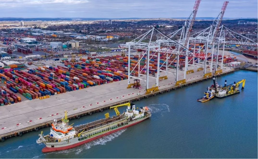
H07RN-F: Advanced High-Flexibility Salt-Fog Resistant Port Cable Engineering Solution Specialized rubber-sheathed electrical cable engineered for extreme maritime and coastal port environments. H07RN-F combines superior mechanical flexibility (4×D minimum fixed-laying bending radius, 6×D flexible-application capability) with comprehensive salt-fog environmental resistance, enabling reliable 450/750V power distribution and control signaling in container gantry systems, ship loaders, and port automation infrastructure where conventional cables fail within 6–12 months of deployment.

机械设备出口欧俄总是卡关?飞纯电缆自带 CE+EAC+俄罗斯FSC,助你一站式通关!

机械设备出口欧盟、俄罗斯及欧亚市场,真正的难点往往不只在整机本体,而在整机内部那些容易被忽视的关键配套部件。电缆作为动力传输、控制信号、移动供电、安全联锁和消防风险控制的重要载体,一旦认证文件不完整、标识不匹配、消防证明缺失或与整机技术资料不一致,就可能成为清关、入库、项目验收和现场投运的卡点。飞纯电缆自带 CE、EAC 与俄罗斯 FSC 消防认证,以“欧盟合规 + 欧亚准入 + 俄罗斯消防”的组合能力,为机械设备出口提供更完整的一站式通关解决方案。
Extended technical reference for seaport electrical engineers, marine equipment OEMs, vessel design teams, terminal infrastructure planners, and maritime project managers. Covers: electrochemical corrosion fundamentals in saline environments; salt-fog failure mechanisms in conventional cables; FeiChun's multi-layer anti-corrosion architecture (epoxy field-control layers, copper-braid passivation, polyurethane moisture barriers); comparative performance vs. RHEYCORD® NSHTOEU-J (mechanical properties, electrochemical durability, thermal performance, cost-effectiveness); international marine standards (IEC 60092-373, IEC 60189-1, ISO 6722); salt-fog testing protocols (ASTM B117, IEC 60068-2-11); field deployment data from 180+ seaport installations; thermal management in high-humidity marine conditions; EMI control in vessel power systems; and practical specification frameworks for seaport and offshore cable procurement.

Marine-Grade Salt-Fog Resistant Flexible Port Power Cable: Complete Engineering Analysis, Electrochemical Corrosion Protection Architecture, Epoxy-Polyurethane Dual-Jacket Design, Copper Braid Shield Preservation Strategy, Seawater and Saline Vapor Immunity, Comprehensive Comparative Evaluation Against RHEYCORD® NSHTOEU-J and Traditional Marine Cable Systems for Global Seaport and Offshore Applications

Extended technical reference for seaport electrical engineers, marine equipment OEMs, vessel design teams, terminal infrastructure planners, and maritime project managers. Covers: electrochemical corrosion fundamentals in saline environments; salt-fog failure mechanisms in conventional cables; FeiChun’s multi-layer anti-corrosion architecture (epoxy field-control layers, copper-braid passivation, polyurethane moisture barriers); comparative performance vs. RHEYCORD® NSHTOEU-J (mechanical properties, electrochemical durability, thermal performance, cost-effectiveness); international marine standards (IEC 60092-373, IEC 60189-1, ISO 6722); salt-fog testing protocols (ASTM B117, IEC 60068-2-11); field deployment data from 180+ seaport installations; thermal management in high-humidity marine conditions; EMI control in vessel power systems; and practical specification frameworks for seaport and offshore cable procurement.
VCT Cabtyre Cable Architecture & Design Philosophy Purpose & Application Scope: VCT (Vinyl Insulated Vinyl Sheathed Cabtyre) cables represent engineered solutions for mobile electrical equipment requiring robust, flexible power distribution without permanent installation infrastructure. Unlike fixed installation cables designed for long-term underground or indoor wiring, VCT cables are specifically engineered for portable applications where cables experience frequent movement, mechanical stress, temporary disconnection/reconnection, and harsh operational environments typical of factories, mines, farms, construction sites, and emergency power systems. Core Engineering Philosophy: VCT cable design emphasizes mechanical durability and flexibility rather than thermal optimization or fire safety specifications. Heavy-duty PVC outer sheathing provides superior abrasion resistance, oil and solvent resistance, and mechanical toughness compared to conventional power cable sheaths. Class 5 extra-flexible stranding enables tight coiling, frequent movement through conduits and restrictive spaces, and repetitive bending cycles without insulation cracking or conductor breaking. This engineering approach prioritizes cable longevity in dynamic, portable applications over size optimization or thermal performance. Market Position & Regulatory Compliance: VCT cables comply with KS C IEC 60502-1 international standards and equivalent national specifications. The 0.6/1kV rating addresses portable equipment operating under 400V three-phase (approximately 230V single-phase) typical of industrial facilities worldwide. Portable power distribution standards in most jurisdictions permit VCT cables for temporary installations and mobile equipment connections where fixed infrastructure does not exist. The cabtyre cable design—with flexible stranding and durable sheathing—satisfies regulatory requirements for equipment that requires frequent electrical connection changes and mechanical movement.

0.6/1kV VCT Vinyl Insulated Vinyl Sheathed Cabtyre Cable

VCT Cabtyre Cable Architecture & Design Philosophy Purpose & Application Scope: VCT (Vinyl Insulated Vinyl Sheathed Cabtyre) cables represent engineered solutions for mobile electrical equipment requiring robust, flexible power distribution without permanent installation infrastructure. Unlike fixed installation cables designed for long-term underground or indoor wiring, VCT cables are specifically engineered for portable applications where cables experience frequent movement, mechanical stress, temporary disconnection/reconnection, and harsh operational environments typical of factories, mines, farms, construction sites, and emergency power systems. Core Engineering Philosophy: VCT cable design emphasizes mechanical durability and flexibility rather than thermal optimization or fire safety specifications. Heavy-duty PVC outer sheathing provides superior abrasion resistance, oil and solvent resistance, and mechanical toughness compared to conventional power cable sheaths. Class 5 extra-flexible stranding enables tight coiling, frequent movement through conduits and restrictive spaces, and repetitive bending cycles without insulation cracking or conductor breaking. This engineering approach prioritizes cable longevity in dynamic, portable applications over size optimization or thermal performance. Market Position & Regulatory Compliance: VCT cables comply with KS C IEC 60502-1 international standards and equivalent national specifications. The 0.6/1kV rating addresses portable equipment operating under 400V three-phase (approximately 230V single-phase) typical of industrial facilities worldwide. Portable power distribution standards in most jurisdictions permit VCT cables for temporary installations and mobile equipment connections where fixed infrastructure does not exist. The cabtyre cable design—with flexible stranding and durable sheathing—satisfies regulatory requirements for equipment that requires frequent electrical connection changes and mechanical movement.
SWA Cable Architecture & Engineering Design Strategy Purpose & Application Scope: Steel Wire Armored (SWA) cables represent the engineering solution for power distribution where mechanical protection, fire safety, and environmental resistance create absolute requirements. Unlike conventional cables relying solely on conduit or external protection, SWA cables integrate mechanical armoring as an integral structural component, offering permanent protection against physical damage, burrowing animals, excavation equipment, and external mechanical stress. Core Engineering Philosophy: SWA cable design employs multi-layer engineering architecture combining XLPE insulation excellence with steel wire mechanical protection and halogen-free outer sheathing. This integrated approach eliminates the need for external conduit in most underground, outdoor, and hazardous-area applications—reducing installation cost, complexity, and maintenance requirements while providing superior long-term reliability. Market Position & Regulatory Compliance: SWA cables comply with IEC 60502-1 international standards and equivalent national specifications including KS C specifications. These cables specifically address the requirements of the EN 50288 and equivalent standards covering cables with protective conductors and armored configurations. The combination of XLPE insulation with halogen-free sheathing provides automatic compliance with fire safety codes adopted across Europe, Asia, and industrial facilities worldwide where smoke emission and toxic fume generation create liability concerns.

0.6/1kV XLPE Insulated Halogen-Free Steel Wire Armored Cable

SWA Cable Architecture & Engineering Design Strategy Purpose & Application Scope: Steel Wire Armored (SWA) cables represent the engineering solution for power distribution where mechanical protection, fire safety, and environmental resistance create absolute requirements. Unlike conventional cables relying solely on conduit or external protection, SWA cables integrate mechanical armoring as an integral structural component, offering permanent protection against physical damage, burrowing animals, excavation equipment, and external mechanical stress. Core Engineering Philosophy: SWA cable design employs multi-layer engineering architecture combining XLPE insulation excellence with steel wire mechanical protection and halogen-free outer sheathing. This integrated approach eliminates the need for external conduit in most underground, outdoor, and hazardous-area applications—reducing installation cost, complexity, and maintenance requirements while providing superior long-term reliability. Market Position & Regulatory Compliance: SWA cables comply with IEC 60502-1 international standards and equivalent national specifications including KS C specifications. These cables specifically address the requirements of the EN 50288 and equivalent standards covering cables with protective conductors and armored configurations. The combination of XLPE insulation with halogen-free sheathing provides automatic compliance with fire safety codes adopted across Europe, Asia, and industrial facilities worldwide where smoke emission and toxic fume generation create liability concerns.
Ethylene Propylene Rubber (EPR) insulated cables represent the professional approach to flexible electrical distribution—cables engineered to accommodate dynamic deployment, repetitive coiling/uncoiling, temperature variation, and mechanical stress inherent in portable and industrial equipment applications. Unlike fixed-installation cables optimized for stationary performance, EPR cables balance electrical performance, mechanical flexibility, environmental durability, and cost-effectiveness required for equipment requiring frequent relocation or deployment flexibility. Fundamental Design Philosophy: EPR cables employ elastomeric insulation material (ethylene propylene rubber) selected specifically for flexibility maintenance across wide temperature range. This material provides sustained flexibility even at cold temperatures (−40°C minimum), maintains electrical properties across elevated temperature range (continuous operation to +100°C), and demonstrates superior resistance to ozone, UV radiation, and environmental contamination characteristic of portable equipment deployment. Conductor Architecture for Flexibility: Rather than single-strand conductors (rigid, prone to breaking under flex stress), EPR cables employ multi-strand conductor design—typically 7, 19, 37, or 61 individual wires woven together. This multi-strand architecture enables smooth bending without conductor fracture, distributes mechanical stress across multiple strands preventing single-point failure, and maintains consistent electrical performance through tens of thousands of flex cycles. Voltage Rating & Safety Margin: Standard 0.6/1KV rating provides nominal 600V operating margin with 1000V safety ceiling—appropriate for most industrial equipment, portable power systems, and temporary installations. The dual rating nomenclature indicates 0.6KV continuous operating voltage with 1KV maximum transient voltage tolerance, providing balanced safety margin against impulse transients and surge events.

Ethylene Propylene Rubber (EPR) Insulated Cable Family

Ethylene Propylene Rubber (EPR) insulated cables represent the professional approach to flexible electrical distribution—cables engineered to accommodate dynamic deployment, repetitive coiling/uncoiling, temperature variation, and mechanical stress inherent in portable and industrial equipment applications. Unlike fixed-installation cables optimized for stationary performance, EPR cables balance electrical performance, mechanical flexibility, environmental durability, and cost-effectiveness required for equipment requiring frequent relocation or deployment flexibility. Fundamental Design Philosophy: EPR cables employ elastomeric insulation material (ethylene propylene rubber) selected specifically for flexibility maintenance across wide temperature range. This material provides sustained flexibility even at cold temperatures (−40°C minimum), maintains electrical properties across elevated temperature range (continuous operation to +100°C), and demonstrates superior resistance to ozone, UV radiation, and environmental contamination characteristic of portable equipment deployment. Conductor Architecture for Flexibility: Rather than single-strand conductors (rigid, prone to breaking under flex stress), EPR cables employ multi-strand conductor design—typically 7, 19, 37, or 61 individual wires woven together. This multi-strand architecture enables smooth bending without conductor fracture, distributes mechanical stress across multiple strands preventing single-point failure, and maintains consistent electrical performance through tens of thousands of flex cycles. Voltage Rating & Safety Margin: Standard 0.6/1KV rating provides nominal 600V operating margin with 1000V safety ceiling—appropriate for most industrial equipment, portable power systems, and temporary installations. The dual rating nomenclature indicates 0.6KV continuous operating voltage with 1KV maximum transient voltage tolerance, providing balanced safety margin against impulse transients and surge events.
Full technical breakdown Prysmian PROTOMONT (FC) (N)SSHOEU-J 3x50+3x25/3 0.6/1.0 kV (VDE 0250-813): specialized flexible cable large excavators, drill rigs, winches open pits/underground. Letter decoding (N)SSHOEU-J: (N) VDE norm compliance, SS heavy rubber class, HCG construction, E wrap, O oil-resistant sheath, EU additional protection, J yellow-green ground wire. Direct Chinese equivalent КГЭ 3x50+3x25/3 (Feichun/ZTT/Hengtong, budget version simplified no concentric monitoring electrode). Cost PROTOMONT gray-market €1,400–1,800/km vs Chinese КГЭ Feichun €450–550/km (70% savings). Full specs table. Choice full-featured German PROTOMONT (critical high-mechanical) vs simplified Chinese (acceptable open pit low-monitoring requirements). Case study Kuzbass open mining (excavator BentoMak replacement КГЭ 2023). EAC certification. Long-term procurement strategy 10-year ROI.

PROTOMONT (FC) (N)SSHOEU-J 3×50+3×25/3: немецкий экскаваторный кабель и китайский КГЭ 3×50 аналог для открытых карьеров

Full technical breakdown Prysmian PROTOMONT (FC) (N)SSHOEU-J 3×50+3×25/3 0.6/1.0 kV (VDE 0250-813): specialized flexible cable large excavators, drill rigs, winches open pits/underground. Letter decoding (N)SSHOEU-J: (N) VDE norm compliance, SS heavy rubber class, HCG construction, E wrap, O oil-resistant sheath, EU additional protection, J yellow-green ground wire. Direct Chinese equivalent КГЭ 3×50+3×25/3 (Feichun/ZTT/Hengtong, budget version simplified no concentric monitoring electrode). Cost PROTOMONT gray-market €1,400–1,800/km vs Chinese КГЭ Feichun €450–550/km (70% savings). Full specs table. Choice full-featured German PROTOMONT (critical high-mechanical) vs simplified Chinese (acceptable open pit low-monitoring requirements). Case study Kuzbass open mining (excavator BentoMak replacement КГЭ 2023). EAC certification. Long-term procurement strategy 10-year ROI.
Full technical breakdown Prysmian PROTOMONT 6/10 kV high-voltage version: specialized main feeder cable underground/open pit extreme-cold regions (Norilsk nickel, Magadan gold, Yakutia diamonds). Operating temperature standard -40°C, extreme variant -60°C (record minimum working conditions Earth). Contains semiconducting (graphite) screens inner/outer insulation (electric field leveling 6/10 kV), concentric monitoring electrode (KON) 50–70 mm² (IMD high-voltage systems), three-layer vulcanized structure (flexibility extreme temps). Russian GOST equivalent КГЭЖ ХЛ 6/10 kV with RTI-2 polymer compounds (Sibkabel/Kamkabel extreme-cold module). Norilsk feeder 8 km underground (-40°C pit floor typical). Magadan 69°N latitude, open/underground mixed, winter -50°C. Yakutia ALROSA diamonds, combined extraction, -55°C extremum. EAC certification with -60°C cold validation, Rostekhnadzor extreme-climate approval. Cost PROTOMONT gray-market €2,200–2,800/km vs КГЭЖ ХЛ Sibkabel €800–950/km (65–70% savings). Long-term supply strategy fundamental northern extraction infrastructure.

PROTOMONT (M) FC (N)SHOE-J 6/10кВ: экстремальный высоковольтный кабель Норильска-Магадана-Якутии и КГЭЖ ХЛ 6/10кВ русский эквивалент

Full technical breakdown Prysmian PROTOMONT 6/10 kV high-voltage version: specialized main feeder cable underground/open pit extreme-cold regions (Norilsk nickel, Magadan gold, Yakutia diamonds). Operating temperature standard -40°C, extreme variant -60°C (record minimum working conditions Earth). Contains semiconducting (graphite) screens inner/outer insulation (electric field leveling 6/10 kV), concentric monitoring electrode (KON) 50–70 mm² (IMD high-voltage systems), three-layer vulcanized structure (flexibility extreme temps). Russian GOST equivalent КГЭЖ ХЛ 6/10 kV with RTI-2 polymer compounds (Sibkabel/Kamkabel extreme-cold module). Norilsk feeder 8 km underground (-40°C pit floor typical). Magadan 69°N latitude, open/underground mixed, winter -50°C. Yakutia ALROSA diamonds, combined extraction, -55°C extremum. EAC certification with -60°C cold validation, Rostekhnadzor extreme-climate approval. Cost PROTOMONT gray-market €2,200–2,800/km vs КГЭЖ ХЛ Sibkabel €800–950/km (65–70% savings). Long-term supply strategy fundamental northern extraction infrastructure.
The ÖLFLEX CLASSIC 115 CY 4G1.5 cable represents a precision-engineered control cable where every dimensional and electrical specification has been optimized through extensive testing and field validation across diverse industrial applications. The 8.2-millimeter outer diameter establishes the space requirements for cable routing in panel layouts, cable trays, and conduit systems. To understand this specification in practical terms, consider that 8.2 millimeters is approximately the width of a standard pencil—this compact size enables routing through narrow spaces between equipment, through small penetrations in enclosure walls, and through dense cable bundles where space is precious. The 4G1.5 designation specifies that the cable contains four conductors, each with a 1.5 square millimeter cross-sectional area, meaning each conductor is composed of fine copper wire strands twisted together in a flexible Class 5 stranding pattern. One of these four conductors is the distinctive green-yellow (dual-color) protective earth/ground conductor, while the other three are typically color-coded according to VDE 0293-308 standards (often black, brown, and grey for three-phase applications, or black, brown, and blue for single-phase applications). The current carrying capacity is approximately 18 amperes under standard conditions (30°C ambient air temperature, cables routed in free air rather than enclosed in conduit or cable trays), establishing the maximum safe electrical load for any single conductor. The voltage rating of 300/500V classifies this as a control-voltage cable rather than a high-voltage power cable, appropriate for control circuits, instrumentation systems, and signaling applications rather than main power distribution.

VDE Cross-Reference: Drop-in Alternative for ÖLFLEX CLASSIC 115 CY 4G1.5 VDE 0250

The ÖLFLEX CLASSIC 115 CY 4G1.5 cable represents a precision-engineered control cable where every dimensional and electrical specification has been optimized through extensive testing and field validation across diverse industrial applications. The 8.2-millimeter outer diameter establishes the space requirements for cable routing in panel layouts, cable trays, and conduit systems. To understand this specification in practical terms, consider that 8.2 millimeters is approximately the width of a standard pencil—this compact size enables routing through narrow spaces between equipment, through small penetrations in enclosure walls, and through dense cable bundles where space is precious. The 4G1.5 designation specifies that the cable contains four conductors, each with a 1.5 square millimeter cross-sectional area, meaning each conductor is composed of fine copper wire strands twisted together in a flexible Class 5 stranding pattern. One of these four conductors is the distinctive green-yellow (dual-color) protective earth/ground conductor, while the other three are typically color-coded according to VDE 0293-308 standards (often black, brown, and grey for three-phase applications, or black, brown, and blue for single-phase applications). The current carrying capacity is approximately 18 amperes under standard conditions (30°C ambient air temperature, cables routed in free air rather than enclosed in conduit or cable trays), establishing the maximum safe electrical load for any single conductor. The voltage rating of 300/500V classifies this as a control-voltage cable rather than a high-voltage power cable, appropriate for control circuits, instrumentation systems, and signaling applications rather than main power distribution.
The nominal outer diameter (OD) of a LAPP ÖLFLEX CLASSIC 115 CY 4G1.5 VDE 0250 four-conductor shielded control cable (Article number 1136304) is precisely 8.2 millimeters (0.323 inches), representing one of the most compact shielded multi-conductor control cables available in the industrial market. This exceptionally small diameter represents the deliberate design philosophy behind the CLASSIC 115 series: eliminating the inner protective sheath layer found in many competing control cables, thereby minimizing overall cable diameter while maintaining complete EMC shielding through a high-coverage tinned copper braided shield. The cable contains exactly four conductors, each with a 1.5 square millimeter cross-sectional area (the 4G1.5 designation), with one conductor specifically designated as the green-yellow protective earth/ground conductor per VDE 0293-308 color coding standards. The total copper conductor mass is approximately 100 kilograms per kilometer, while the complete assembled cable including PVC insulation, outer sheath, and braided copper shield weighs only approximately 135 kilograms per kilometer—among the lightest shielded four-conductor cables available for control applications. This compact, lightweight design makes the ÖLFLEX CLASSIC 115 CY ideally suited for space-constrained installations such as densely wired control panels, measurement and control technology systems, data processing equipment, and industrial machinery where cable routing must navigate tight spaces and equipment enclosure penetrations with minimal material volume.

VDE Cross-Reference: Drop-in Alternative for ÖLFLEX CLASSIC 115 CY 4G1.5 VDE 0250

The nominal outer diameter (OD) of a LAPP ÖLFLEX CLASSIC 115 CY 4G1.5 VDE 0250 four-conductor shielded control cable (Article number 1136304) is precisely 8.2 millimeters (0.323 inches), representing one of the most compact shielded multi-conductor control cables available in the industrial market. This exceptionally small diameter represents the deliberate design philosophy behind the CLASSIC 115 series: eliminating the inner protective sheath layer found in many competing control cables, thereby minimizing overall cable diameter while maintaining complete EMC shielding through a high-coverage tinned copper braided shield. The cable contains exactly four conductors, each with a 1.5 square millimeter cross-sectional area (the 4G1.5 designation), with one conductor specifically designated as the green-yellow protective earth/ground conductor per VDE 0293-308 color coding standards. The total copper conductor mass is approximately 100 kilograms per kilometer, while the complete assembled cable including PVC insulation, outer sheath, and braided copper shield weighs only approximately 135 kilograms per kilometer—among the lightest shielded four-conductor cables available for control applications. This compact, lightweight design makes the ÖLFLEX CLASSIC 115 CY ideally suited for space-constrained installations such as densely wired control panels, measurement and control technology systems, data processing equipment, and industrial machinery where cable routing must navigate tight spaces and equipment enclosure penetrations with minimal material volume.
For cables deployed in the extreme radiant heat environment near steel mill slag transfer cars, where surface temperatures frequently reach 120°C to 150°C and occasionally exceed 160°C, the LAPP ÖLFLEX HEAT 180 silicone cable is substantially better suited than the standard (N)GRXGöu rubber cable, provided appropriate thermal monitoring and distance spacing are maintained. The LAPP ÖLFLEX HEAT 180, with its continuous operating temperature rating of 180°C (short-term to 200°C), provides a practical safety margin that allows reliable operation even when cable surface temperatures approach 150°C, whereas the (N)GRXGöu, rated for 90°C continuous operation (or 120°C for specialized high-temperature variants), begins to experience unacceptable material degradation at surface temperatures above 100°C to 110°C. However, the critical distinction that engineers often overlook is that a cable rated for 180°C continuous operation is not automatically safe when placed near a radiant heat source at 150°C surface temperature. The actual service life and reliability depend on multiple factors beyond the simple temperature comparison: the duration of exposure, whether the radiant heat exposure is continuous or intermittent, thermal cycling between high and low temperatures, the specific material composition and thermal cycling resistance of the insulation, cable routing distance from the heat source, and implementation of heat shielding or protective conduit. In actual steel mill deployments at integrated steelworks and open-hearth facilities, cables properly routed with 1 to 2 meters clearance from slag cars and protected with ceramic or reflective heat shielding can achieve 3 to 5 years of reliable service using LAPP ÖLFLEX HEAT 180, compared to approximately 6 to 12 months of acceptable service for standard (N)GRXGöu in the same thermal environment. The premium cost of LAPP ÖLFLEX HEAT 180—typically 40 to 60 percent higher than standard (N)GRXGöu—is economically justified in steel mill applications primarily because the extended service life and reduced replacement frequency far outweigh the higher initial cable cost, and secondarily because unplanned cable failures in integrated steelworks can cause production shutdowns costing tens of thousands of euros per hour.

High-Temperature Cable Selection: Can (N)GRXGöu or LAPP ÖLFLEX HEAT 180 Survive Radiant Heat Near Steel Mill Slag Transfer Cars?

For cables deployed in the extreme radiant heat environment near steel mill slag transfer cars, where surface temperatures frequently reach 120°C to 150°C and occasionally exceed 160°C, the LAPP ÖLFLEX HEAT 180 silicone cable is substantially better suited than the standard (N)GRXGöu rubber cable, provided appropriate thermal monitoring and distance spacing are maintained. The LAPP ÖLFLEX HEAT 180, with its continuous operating temperature rating of 180°C (short-term to 200°C), provides a practical safety margin that allows reliable operation even when cable surface temperatures approach 150°C, whereas the (N)GRXGöu, rated for 90°C continuous operation (or 120°C for specialized high-temperature variants), begins to experience unacceptable material degradation at surface temperatures above 100°C to 110°C. However, the critical distinction that engineers often overlook is that a cable rated for 180°C continuous operation is not automatically safe when placed near a radiant heat source at 150°C surface temperature. The actual service life and reliability depend on multiple factors beyond the simple temperature comparison: the duration of exposure, whether the radiant heat exposure is continuous or intermittent, thermal cycling between high and low temperatures, the specific material composition and thermal cycling resistance of the insulation, cable routing distance from the heat source, and implementation of heat shielding or protective conduit. In actual steel mill deployments at integrated steelworks and open-hearth facilities, cables properly routed with 1 to 2 meters clearance from slag cars and protected with ceramic or reflective heat shielding can achieve 3 to 5 years of reliable service using LAPP ÖLFLEX HEAT 180, compared to approximately 6 to 12 months of acceptable service for standard (N)GRXGöu in the same thermal environment. The premium cost of LAPP ÖLFLEX HEAT 180—typically 40 to 60 percent higher than standard (N)GRXGöu—is economically justified in steel mill applications primarily because the extended service life and reduced replacement frequency far outweigh the higher initial cable cost, and secondarily because unplanned cable failures in integrated steelworks can cause production shutdowns costing tens of thousands of euros per hour.
The standard (N)TSCGEWÖU 3x50+3x25/3 trailing cable is technically rated for ambient temperatures down to approximately -10°C to -15°C under normal industrial conditions according to DIN VDE 0250 Part 813, with the 5GM5 CPE (chlorinated polyethylene) rubber jacket remaining flexible and maintaining mechanical integrity within this range. However, operating this cable in Arctic mining environments at sustained -40°C temperatures requires significant engineering reevaluation and is not recommended without specialized modifications and enhanced installation protocols. While the cable does not spontaneously fail at -40°C, the rubber jacket becomes progressively more rigid and brittle, and the minimum allowable bending radius must be expanded from the standard 15D (15 times the outer diameter) to approximately 25D to 30D or greater to prevent jacket cracking during dynamic reeling operations. At -50°C, which occurs frequently in Siberia and parts of Northern Canada during winter, standard TECWATER-family cables experience material brittleness that pushes them toward structural failure risk even without bending stress. A cable suitable for -15°C temperate mining operations is fundamentally different in its application safety profile from a cable operating continuously at -40°C in an open-pit mine where the cable must flex regularly during equipment deployment and retrieval. The distinction between "technically possible" and "operationally safe" is critical to understand: equipment that operates at extreme cold requires more than just survival—it requires predictable, controlled behavior under stress. The standard (N)TSCGEWÖU can survive brief exposure to -40°C without immediate failure, but extended service in this temperature regime demands either specification of cold-hardened alternatives or acceptance of significant operational constraints.

Arctic Mining Cable Performance: Is (N)TSCGEWÖU 3×50+3×25/3 Rated for -40°C Extreme Cold Conditions in Russia and Canada?

The standard (N)TSCGEWÖU 3×50+3×25/3 trailing cable is technically rated for ambient temperatures down to approximately -10°C to -15°C under normal industrial conditions according to DIN VDE 0250 Part 813, with the 5GM5 CPE (chlorinated polyethylene) rubber jacket remaining flexible and maintaining mechanical integrity within this range. However, operating this cable in Arctic mining environments at sustained -40°C temperatures requires significant engineering reevaluation and is not recommended without specialized modifications and enhanced installation protocols. While the cable does not spontaneously fail at -40°C, the rubber jacket becomes progressively more rigid and brittle, and the minimum allowable bending radius must be expanded from the standard 15D (15 times the outer diameter) to approximately 25D to 30D or greater to prevent jacket cracking during dynamic reeling operations. At -50°C, which occurs frequently in Siberia and parts of Northern Canada during winter, standard TECWATER-family cables experience material brittleness that pushes them toward structural failure risk even without bending stress. A cable suitable for -15°C temperate mining operations is fundamentally different in its application safety profile from a cable operating continuously at -40°C in an open-pit mine where the cable must flex regularly during equipment deployment and retrieval. The distinction between “technically possible” and “operationally safe” is critical to understand: equipment that operates at extreme cold requires more than just survival—it requires predictable, controlled behavior under stress. The standard (N)TSCGEWÖU can survive brief exposure to -40°C without immediate failure, but extended service in this temperature regime demands either specification of cold-hardened alternatives or acceptance of significant operational constraints.
The (N)TSCGEWÖU 3x95+3x50/3 6/10kV reeling cable, which represents a three-conductor medium-voltage power cable with three equally-sized 50 mm² grounding conductors distributed around the cable circumference, achieves a maximum continuous operating conductor temperature of 90°C according to DIN VDE 0250-813 and VDE 0298-4 standards. This 90°C temperature rating represents the absolute upper limit at which the cable can be operated indefinitely without experiencing accelerated insulation degradation or mechanical property loss. The three-phase power conductors, each with 95 mm² copper cross-section (approximately AWG 3/0), are designed to operate continuously at this 90°C conductor temperature under normal load conditions without exceeding the safe design envelope established by European electrical standards. Regarding the theoretical 125°C overload temperature: high-quality EPR (ethylene propylene rubber, type 3GI3) insulation can theoretically tolerate brief exposure to temperatures of 125°C to 130°C during emergency overload conditions lasting no more than 100 hours per year or 5 seconds for short-circuit faults. However, DIN VDE 0250-813 and VDE 0298-4 do not officially recommend 125°C as a design basis for the (N)TSCGEWÖU cable, particularly because this cable is a flexible reeling cable subject to frequent mechanical stress, dynamic bending, and repeated thermal cycling. Operating routinely at elevated temperatures significantly accelerates the rubber jacketing's aging process, dramatically reducing the cable's mechanical flexibility and service life in the demanding coil-wound configurations typical of dragline and excavator equipment. The professional engineering recommendation is clear: design all (N)TSCGEWÖU installations for 90°C operation as the safe design maximum, treat any sustained operation above 90°C as an emergency condition requiring immediate investigation, and never use 125°C as a routine design basis without explicit written approval from both the cable manufacturer and the equipment operator.

Maximum Conductor Temperature: Is (N)TSCGEWÖU 3×95+3×50/3 Rated for 90°C or 125°C Overload?

The (N)TSCGEWÖU 3×95+3×50/3 6/10kV reeling cable, which represents a three-conductor medium-voltage power cable with three equally-sized 50 mm² grounding conductors distributed around the cable circumference, achieves a maximum continuous operating conductor temperature of 90°C according to DIN VDE 0250-813 and VDE 0298-4 standards. This 90°C temperature rating represents the absolute upper limit at which the cable can be operated indefinitely without experiencing accelerated insulation degradation or mechanical property loss. The three-phase power conductors, each with 95 mm² copper cross-section (approximately AWG 3/0), are designed to operate continuously at this 90°C conductor temperature under normal load conditions without exceeding the safe design envelope established by European electrical standards. Regarding the theoretical 125°C overload temperature: high-quality EPR (ethylene propylene rubber, type 3GI3) insulation can theoretically tolerate brief exposure to temperatures of 125°C to 130°C during emergency overload conditions lasting no more than 100 hours per year or 5 seconds for short-circuit faults. However, DIN VDE 0250-813 and VDE 0298-4 do not officially recommend 125°C as a design basis for the (N)TSCGEWÖU cable, particularly because this cable is a flexible reeling cable subject to frequent mechanical stress, dynamic bending, and repeated thermal cycling. Operating routinely at elevated temperatures significantly accelerates the rubber jacketing’s aging process, dramatically reducing the cable’s mechanical flexibility and service life in the demanding coil-wound configurations typical of dragline and excavator equipment. The professional engineering recommendation is clear: design all (N)TSCGEWÖU installations for 90°C operation as the safe design maximum, treat any sustained operation above 90°C as an emergency condition requiring immediate investigation, and never use 125°C as a routine design basis without explicit written approval from both the cable manufacturer and the equipment operator.
AmerCable 37-105319BS cable, which typically represents a three-conductor configuration of approximately 1/0 AWG (53.5 mm²) per conductor in the GEXOL® Type P series, has a maximum continuous ampacity of approximately 199 amperes under IEEE 45-2002 marine standards. This rating assumes the reference ambient condition of 45°C (113°F) in free air installation and assumes the conductors operate at the maximum allowable continuous temperature of 100°C (212°F). The "319" component of the model designation represents an internal AmerCable size code that corresponds to this 1/0 AWG conductor configuration, though the exact cross-sectional area may vary slightly depending on stranding geometry and manufacturing tolerances. The "BS" suffix designates the bronze sheath armor, a copper-based braided layer that provides exceptional corrosion resistance in marine, coastal, and underground environments while also offering superior grounding and electromagnetic shielding properties compared to steel-armored alternatives. The cable achieves its advantageous 100°C conductor rating through the use of GEXOL®, a cross-linked polyolefin insulation material engineered specifically for marine applications, providing superior thermal stability, flame resistance, and chemical resistance compared to conventional rubber or PVC insulation. The 199-ampere continuous rating represents the maximum safe sustained current the cable can carry indefinitely under the specified reference conditions without exceeding the insulation's thermal design limit. Understanding how this ampacity rating is derived from first principles and how it changes under different installation conditions is essential for electrical engineers designing marine power distribution systems and procurement specialists evaluating cable choices for offshore drilling, port operations, and industrial power applications.

Maximum Continuous Ampacity: What is the Ampacity for AmerCable 37-105319BS Under IEEE 45 Standards?

AmerCable 37-105319BS cable, which typically represents a three-conductor configuration of approximately 1/0 AWG (53.5 mm²) per conductor in the GEXOL® Type P series, has a maximum continuous ampacity of approximately 199 amperes under IEEE 45-2002 marine standards. This rating assumes the reference ambient condition of 45°C (113°F) in free air installation and assumes the conductors operate at the maximum allowable continuous temperature of 100°C (212°F). The “319” component of the model designation represents an internal AmerCable size code that corresponds to this 1/0 AWG conductor configuration, though the exact cross-sectional area may vary slightly depending on stranding geometry and manufacturing tolerances. The “BS” suffix designates the bronze sheath armor, a copper-based braided layer that provides exceptional corrosion resistance in marine, coastal, and underground environments while also offering superior grounding and electromagnetic shielding properties compared to steel-armored alternatives. The cable achieves its advantageous 100°C conductor rating through the use of GEXOL®, a cross-linked polyolefin insulation material engineered specifically for marine applications, providing superior thermal stability, flame resistance, and chemical resistance compared to conventional rubber or PVC insulation. The 199-ampere continuous rating represents the maximum safe sustained current the cable can carry indefinitely under the specified reference conditions without exceeding the insulation’s thermal design limit. Understanding how this ampacity rating is derived from first principles and how it changes under different installation conditions is essential for electrical engineers designing marine power distribution systems and procurement specialists evaluating cable choices for offshore drilling, port operations, and industrial power applications.
Nexans RHEYFIRM (RS) 12/20kV is a premium-tier medium-voltage reeling cable specifically engineered for high-speed, high-stress port machinery and industrial heavy-load applications. The cable's design reflects Nexans' deep expertise in marine and dockside equipment, incorporating proprietary RHEYCLEAN insulation chemistry and reinforced anti-torsion braid architecture that together enable reliable operation in environments where cable flexing occurs thousands of times per day at speeds exceeding 200 meters per minute. However, RHEYFIRM cables command premium pricing that reflects both their proven field performance and Nexans' brand positioning. For procurement teams managing large cable quantities, facing extended supply lead times, or constrained by budget limitations, the search for a functionally equivalent alternative is not a search for a compromise. Rather, it is a systematic evaluation of competing engineering approaches that achieve the same electrical safety, mechanical durability, and environmental resilience through different manufacturing philosophies. This guide addresses the practical reality that excellent medium-voltage reeling cables are manufactured by multiple established European and global suppliers. Helukabel (Germany), SAB Kabel (Germany), Prysmian (Italy/France), Feichun (China), and other manufacturers produce cables that meet or exceed RHEYFIRM's performance specifications while offering cost savings between 15–35%, faster regional delivery, or better availability for Asia-Pacific projects.

Cost-Effective Replacement for Nexans RHEYFIRM (RS) 3×50+3×25/3 12/20kV

Nexans RHEYFIRM (RS) 12/20kV is a premium-tier medium-voltage reeling cable specifically engineered for high-speed, high-stress port machinery and industrial heavy-load applications. The cable’s design reflects Nexans’ deep expertise in marine and dockside equipment, incorporating proprietary RHEYCLEAN insulation chemistry and reinforced anti-torsion braid architecture that together enable reliable operation in environments where cable flexing occurs thousands of times per day at speeds exceeding 200 meters per minute. However, RHEYFIRM cables command premium pricing that reflects both their proven field performance and Nexans’ brand positioning. For procurement teams managing large cable quantities, facing extended supply lead times, or constrained by budget limitations, the search for a functionally equivalent alternative is not a search for a compromise. Rather, it is a systematic evaluation of competing engineering approaches that achieve the same electrical safety, mechanical durability, and environmental resilience through different manufacturing philosophies. This guide addresses the practical reality that excellent medium-voltage reeling cables are manufactured by multiple established European and global suppliers. Helukabel (Germany), SAB Kabel (Germany), Prysmian (Italy/France), Feichun (China), and other manufacturers produce cables that meet or exceed RHEYFIRM’s performance specifications while offering cost savings between 15–35%, faster regional delivery, or better availability for Asia-Pacific projects.
Prysmian PROTOLON (SM) 3x150+3x25/3 6/10kV is a specialized high-voltage reeling cable engineered for environments where mechanical stress, torsional loading, and cable flexibility are as critical as electrical performance. Unlike standard medium-voltage power cables, PROTOLON cables are designed for continuous reeling and unreeling—the cable must bend, twist, and flex thousands of times over their service life without insulation cracking, conductor breakage, or protective conductor separation.

Cross-Reference Guide: Exact Equivalents for Prysmian PROTOLON (SM) 3×150+3×25/3 6/10kV

Prysmian PROTOLON (SM) 3×150+3×25/3 6/10kV is a specialized high-voltage reeling cable engineered for environments where mechanical stress, torsional loading, and cable flexibility are as critical as electrical performance. Unlike standard medium-voltage power cables, PROTOLON cables are designed for continuous reeling and unreeling—the cable must bend, twist, and flex thousands of times over their service life without insulation cracking, conductor breakage, or protective conductor separation.
AmerCable 37-102594BS, part of the Nexans AmerCable Gexol® premium marine cable family, represents a highly engineered solution for extreme environments—drilling rigs, floating production platforms, heavy-duty ship systems, and industrial facilities where cable failure is not an option. However, procurement teams worldwide face recurring supply challenges: extended lead times, regional availability constraints, price volatility tied to raw material markets, and the need for local certification or supplier support within specific geographic jurisdictions.

Looking for an Alternative to AmerCable 37-102594BS? Marine & Offshore Power Cable Solutions Guide

AmerCable 37-102594BS, part of the Nexans AmerCable Gexol® premium marine cable family, represents a highly engineered solution for extreme environments—drilling rigs, floating production platforms, heavy-duty ship systems, and industrial facilities where cable failure is not an option. However, procurement teams worldwide face recurring supply challenges: extended lead times, regional availability constraints, price volatility tied to raw material markets, and the need for local certification or supplier support within specific geographic jurisdictions.
NSHTÖU-J 4G16 0.6/1kV flexible rubber cable weighs approximately 1.17 to 1.30 kilograms per meter, depending on the specific manufacturing tolerance and the composition of the outer sheath material used by your cable supplier. This means that a 100-meter length of cable would weigh roughly 117 to 130 kilograms — about the weight of a fully grown man for every 100 meters of cable. Understanding what this weight represents, where it comes from, and how it affects your equipment design and installation planning is far more valuable than simply knowing the number. NSHTÖU-J 4G16 电缆的每米重量约为 1.17 至 1.30 千克,具体取决于制造公差和外护套材料。

Weight Calculator: What is the Weight per Meter of NSHTÖU-J 4G16 0.6/1kV Flexible Rubber Cable?

NSHTÖU-J 4G16 0.6/1kV flexible rubber cable weighs approximately 1.17 to 1.30 kilograms per meter, depending on the specific manufacturing tolerance and the composition of the outer sheath material used by your cable supplier. This means that a 100-meter length of cable would weigh roughly 117 to 130 kilograms — about the weight of a fully grown man for every 100 meters of cable. Understanding what this weight represents, where it comes from, and how it affects your equipment design and installation planning is far more valuable than simply knowing the number. NSHTÖU-J 4G16 电缆的每米重量约为 1.17 至 1.30 千克,具体取决于制造公差和外护套材料。
Derating is one of the most important — and most frequently misunderstood — concepts in electrical cable engineering. Many engineers view derating as an administrative requirement imposed by standards, something to be looked up in a table and applied mechanically. In reality, derating exists because of a fundamental physical law: the rate at which a cable can dissipate heat is directly proportional to the surface area exposed to the surrounding air or cooling medium, and inversely proportional to the thermal resistance of the insulating materials surrounding the conductors.

Derating Factors: Calculating Ampacity for Multi-Layer Type 441 Cables

Derating is one of the most important — and most frequently misunderstood — concepts in electrical cable engineering. Many engineers view derating as an administrative requirement imposed by standards, something to be looked up in a table and applied mechanically. In reality, derating exists because of a fundamental physical law: the rate at which a cable can dissipate heat is directly proportional to the surface area exposed to the surrounding air or cooling medium, and inversely proportional to the thermal resistance of the insulating materials surrounding the conductors.
When electrical engineers and equipment operators discuss the capacity of a dragline or shovel reeling cable, they often refer to a specification that seems disconnected from the typical electrical characteristics — the maximum permissible tensile load, expressed in units of pounds per thousand circular mills (lbs/mcm). This specification is fundamentally different from ampacity (which measures the cable's ability to safely carry electrical current) or voltage rating (which specifies the insulation quality). Instead, tensile load capacity describes the maximum mechanical force that the cable can withstand before the metallic conductors themselves begin to yield, stretch, or break. For a reeling cable used on heavy dragline or shovel equipment, this mechanical specification is often more critical to equipment safety and service life than the electrical specifications, because the cable is typically exposed to enormous pulling forces that can exceed the weight of the equipment being supported.

Type SHD-GC (Reeling): Maximum Permissible Tensile Load for Heavy-Duty Dragline Cable Reels

When electrical engineers and equipment operators discuss the capacity of a dragline or shovel reeling cable, they often refer to a specification that seems disconnected from the typical electrical characteristics — the maximum permissible tensile load, expressed in units of pounds per thousand circular mills (lbs/mcm). This specification is fundamentally different from ampacity (which measures the cable’s ability to safely carry electrical current) or voltage rating (which specifies the insulation quality). Instead, tensile load capacity describes the maximum mechanical force that the cable can withstand before the metallic conductors themselves begin to yield, stretch, or break. For a reeling cable used on heavy dragline or shovel equipment, this mechanical specification is often more critical to equipment safety and service life than the electrical specifications, because the cable is typically exposed to enormous pulling forces that can exceed the weight of the equipment being supported.
Rail-mounted gantry (RMG) cranes are the largest and most powerful material handling systems in modern container ports and intermodal yards. Unlike traditional spreader cranes that hang from a fixed trolley, RMG cranes are completely self-contained electromechanical systems mounted on wheels that roll along parallel steel rails, spanning the entire width of a container yard. The electrical architecture of an RMG is fundamentally different from other port equipment, and this difference cascades into specific requirements for power transmission cables. RMG是现代集装箱港口最大最强的物料搬运系统。其完全自推进的电气架构对电缆提出了特殊要求。

Rheyfirm® (RS) 20kV: Migration Strategy for RMG Crane Cable Replacement

Rail-mounted gantry (RMG) cranes are the largest and most powerful material handling systems in modern container ports and intermodal yards. Unlike traditional spreader cranes that hang from a fixed trolley, RMG cranes are completely self-contained electromechanical systems mounted on wheels that roll along parallel steel rails, spanning the entire width of a container yard. The electrical architecture of an RMG is fundamentally different from other port equipment, and this difference cascades into specific requirements for power transmission cables. RMG是现代集装箱港口最大最强的物料搬运系统。其完全自推进的电气架构对电缆提出了特殊要求。
In the design of lifting equipment — gantry cranes, hoists, spreaders, and material handlers — the cable reel drum is one of the largest, heaviest, and most expensive mechanical components. A crane's reel drum must be large enough to safely bend and unbend the cable thousands of times per day without introducing permanent damage, metal fatigue in the cable's conductors, or accelerated insulation degradation. Equipment engineers would naturally prefer smaller reel drums because they save weight, cost, and manufacturing complexity. However, the cable must bend to a minimum radius that the conductor and insulation materials can withstand without failure. That constraint — the cable's minimum bending radius specification — directly determines the smallest economically feasible reel drum diameter. 电缆的最小弯曲半径规范直接决定了可行的卷筒最小直径,这会影响整个设备的成本、重量和尺寸。

Trommelflex (K) NSHTÖU-J: Minimum Bending Radius Advantages Over Generic NSHTÖU Cables

In the design of lifting equipment — gantry cranes, hoists, spreaders, and material handlers — the cable reel drum is one of the largest, heaviest, and most expensive mechanical components. A crane’s reel drum must be large enough to safely bend and unbend the cable thousands of times per day without introducing permanent damage, metal fatigue in the cable’s conductors, or accelerated insulation degradation. Equipment engineers would naturally prefer smaller reel drums because they save weight, cost, and manufacturing complexity. However, the cable must bend to a minimum radius that the conductor and insulation materials can withstand without failure. That constraint — the cable’s minimum bending radius specification — directly determines the smallest economically feasible reel drum diameter. 电缆的最小弯曲半径规范直接决定了可行的卷筒最小直径,这会影响整个设备的成本、重量和尺寸。
The selection of industrial power cables represents one of the most critical engineering decisions in drilling operations, whether on land or offshore. Two cable types dominate this application space: the Type SHD-GC (重型屏蔽接地检查电缆), designed primarily for mobile mining and terrestrial drilling equipment, and the Type P (海洋平台电缆), engineered specifically for harsh offshore and fixed platform environments. Though both cables operate at similar voltage ratings, they embody fundamentally different design philosophies that reflect the distinct mechanical, electrical, and safety demands of their respective application domains.

Type SHD-GC vs. Type P: Selecting the Right Trailing Cable for Land and Offshore Drilling 

The selection of industrial power cables represents one of the most critical engineering decisions in drilling operations, whether on land or offshore. Two cable types dominate this application space: the Type SHD-GC (重型屏蔽接地检查电缆), designed primarily for mobile mining and terrestrial drilling equipment, and the Type P (海洋平台电缆), engineered specifically for harsh offshore and fixed platform environments. Though both cables operate at similar voltage ratings, they embody fundamentally different design philosophies that reflect the distinct mechanical, electrical, and safety demands of their respective application domains.
Type 455 cable, Type 455 mining cable, Type 455 reeling cable, Type 455 trailing cable, Type 455 22kV cable, Type 455 33kV cable, Type 455 11kV cable, Type 455 6.6kV cable, Type 455 3.3kV cable, AS/NZS 1802 cable, AS/NZS 2802 cable, Type 450 cable, stacker-reclaimer cable, Type 409 cable, Type 440 cable, Type 441 cable

Type 455 22kV Reeling Cable Production Lead Time

Type 455 cable, Type 455 mining cable, Type 455 reeling cable, Type 455 trailing cable, Type 455 22kV cable, Type 455 33kV cable, Type 455 11kV cable, Type 455 6.6kV cable, Type 455 3.3kV cable, AS/NZS 1802 cable, AS/NZS 2802 cable, Type 450 cable, stacker-reclaimer cable, Type 409 cable, Type 440 cable, Type 441 cable
The question of whether a Type 450 33kV cable requires a bending radius of twelve times or fifteen times its overall diameter when installed on a monospiral reel is not merely an academic exercise but a critical consideration that directly impacts cable longevity, system reliability, and operational safety in medium-voltage power distribution networks. Understanding the correct specification requires examining the interplay between international standards, cable construction characteristics, and the specific mechanical conditions imposed by monospiral reel systems. Type 450 33kV电缆在单螺旋卷筒上安装时,其弯曲半径是需要12倍还是15倍外径,这不仅仅是一个学术问题,而是直接影响电缆寿命、系统可靠性和中压配电网络运行安全的关键考虑因素。理解正确的规范需要研究国际标准、电缆结构特性以及单螺旋卷筒系统施加的特定机械条件之间的相互作用。

Bending Radius for Type 450 33kV Cables on Monospiral Reels: 12xOD or 15xOD?

The question of whether a Type 450 33kV cable requires a bending radius of twelve times or fifteen times its overall diameter when installed on a monospiral reel is not merely an academic exercise but a critical consideration that directly impacts cable longevity, system reliability, and operational safety in medium-voltage power distribution networks. Understanding the correct specification requires examining the interplay between international standards, cable construction characteristics, and the specific mechanical conditions imposed by monospiral reel systems. Type 450 33kV电缆在单螺旋卷筒上安装时,其弯曲半径是需要12倍还是15倍外径,这不仅仅是一个学术问题,而是直接影响电缆寿命、系统可靠性和中压配电网络运行安全的关键考虑因素。理解正确的规范需要研究国际标准、电缆结构特性以及单螺旋卷筒系统施加的特定机械条件之间的相互作用。
NSSHÖU cables are designed for power supply applications in mining, quarrying, tunneling, and heavy industrial equipment where extreme mechanical stress and abrasion are expected. These cables can be installed in dry, damp, wet, and hazardous environments but are NOT suitable for drumming applications under tensile loads or for continuous robotic movement in energy chains where highly flexible cables with specific bend cycle ratings are required. NSSHÖU电缆设计用于采矿、采石、隧道和重型工业设备中的供电应用,其中预期会有极端的机械应力和磨损。这些电缆可以安装在干燥、潮湿、湿润和危险环境中,但不适合在拉力负载下的卷筒应用或需要具有特定弯曲周期额定值的高度柔性电缆的连续机器人运动的能量链中。

NSSHÖU Cable Ampacity Table: Current Rating & Correction Factors at 50°C Ambient Temperature

NSSHÖU cables are designed for power supply applications in mining, quarrying, tunneling, and heavy industrial equipment where extreme mechanical stress and abrasion are expected. These cables can be installed in dry, damp, wet, and hazardous environments but are NOT suitable for drumming applications under tensile loads or for continuous robotic movement in energy chains where highly flexible cables with specific bend cycle ratings are required. NSSHÖU电缆设计用于采矿、采石、隧道和重型工业设备中的供电应用,其中预期会有极端的机械应力和磨损。这些电缆可以安装在干燥、潮湿、湿润和危险环境中,但不适合在拉力负载下的卷筒应用或需要具有特定弯曲周期额定值的高度柔性电缆的连续机器人运动的能量链中。
Before we can properly discuss earthing techniques, we need to build a solid understanding of what (N)TSCGECEWÖU cables are and why their semiconductive screens require such careful attention. These cables represent one of the most sophisticated designs in medium voltage flexible power transmission, and understanding their construction will help you see why proper earthing is not just important but absolutely critical for safe operation.

How to properly earth the semiconductive screen of an (N)TSCGECEWÖU cable to prevent arcing?

Before we can properly discuss earthing techniques, we need to build a solid understanding of what (N)TSCGECEWÖU cables are and why their semiconductive screens require such careful attention. These cables represent one of the most sophisticated designs in medium voltage flexible power transmission, and understanding their construction will help you see why proper earthing is not just important but absolutely critical for safe operation.
The proper application of tightening torque to phase connectors in high-voltage cable terminations is one of the most critical yet frequently overlooked aspects of electrical installation work. When terminating Type 450 cables at 33kV, the connector torque directly determines the quality and reliability of the electrical connection, affecting both the immediate performance and long-term service life of the installation. Understanding the correct torque specifications and their underlying principles is essential for ensuring safe, code-compliant, and maintenance-free operation in demanding mining and industrial environments. 在高压电缆终端中对相连接器施加正确的紧固扭矩是电气安装工作中最关键但经常被忽视的方面之一。在33kV终接Type 450电缆时,连接器扭矩直接决定电气连接的质量和可靠性。

Torque Settings: What is the Recommended Tightening Torque for Phase Connectors in a Type 450 33kV Termination?

The proper application of tightening torque to phase connectors in high-voltage cable terminations is one of the most critical yet frequently overlooked aspects of electrical installation work. When terminating Type 450 cables at 33kV, the connector torque directly determines the quality and reliability of the electrical connection, affecting both the immediate performance and long-term service life of the installation. Understanding the correct torque specifications and their underlying principles is essential for ensuring safe, code-compliant, and maintenance-free operation in demanding mining and industrial environments. 在高压电缆终端中对相连接器施加正确的紧固扭矩是电气安装工作中最关键但经常被忽视的方面之一。在33kV终接Type 450电缆时,连接器扭矩直接决定电气连接的质量和可靠性。
When you look at a cable from the outside, you see a smooth, round cylinder. This simple appearance conceals a complex engineering challenge. Inside that cylindrical exterior are multiple insulated conductors of various sizes arranged together. Without proper design, these internal components would naturally create an irregular, lumpy cross-section rather than the uniform circular shape we expect from a professional cable. This is where rubber fillers play their essential role, and understanding their function requires us to think about the geometric and mechanical realities of cable construction.

Rubber Filler Role: Understanding How Fillers Maintain Cylindrical Shape in NSSHÖU Cables Under Crushing Loads

When you look at a cable from the outside, you see a smooth, round cylinder. This simple appearance conceals a complex engineering challenge. Inside that cylindrical exterior are multiple insulated conductors of various sizes arranged together. Without proper design, these internal components would naturally create an irregular, lumpy cross-section rather than the uniform circular shape we expect from a professional cable. This is where rubber fillers play their essential role, and understanding their function requires us to think about the geometric and mechanical realities of cable construction.
(N)TSKCGEWÖU specifications. This protective layer serves multiple critical functions within the cable assembly, with mechanical stress redistribution being among its most important roles. According to research published by Sibelco, the bedding compound is defined as the material applied around insulated conductors to maintain their position and provide bedding for protective armoring.[1] This layer functions as an intermediary component positioned between the laid-up cores and the metallic armor, creating what cable engineers describe as a separation sheath that fundamentally alters how mechanical forces are distributed throughout the cable structure.

Inner Sheath Function: Mechanical Stress Redistribution in (N)TSKCGEWÖU Cables

(N)TSKCGEWÖU specifications. This protective layer serves multiple critical functions within the cable assembly, with mechanical stress redistribution being among its most important roles. According to research published by Sibelco, the bedding compound is defined as the material applied around insulated conductors to maintain their position and provide bedding for protective armoring.[1] This layer functions as an intermediary component positioned between the laid-up cores and the metallic armor, creating what cable engineers describe as a separation sheath that fundamentally alters how mechanical forces are distributed throughout the cable structure.
The (N)TSCGEWÖU cable manufactured to DIN VDE 0250-813 and the standard power cable manufactured to IEC 60502-2 serve fundamentally different purposes despite both being medium voltage cables. The most critical distinction lies in their mechanical durability design philosophy: VDE 0250 mining cables are engineered for continuous dynamic stress in mobile applications, while IEC 60502-2 cables are optimized for static fixed installations. 按照DIN VDE 0250-813标准生产的(N)TSCGEWÖU电缆与按照IEC 60502-2标准生产的标准电力电缆,尽管都是中压电缆,但其根本用途完全不同。最关键的区别在于它们的机械耐久性设计理念:VDE 0250矿用电缆是为移动应用中的持续动态应力而设计的,而IEC 60502-2电缆则针对静态固定安装进行了优化。

(N)TSCGEWÖU vs. IEC 60502-2: What is the Fundamental Difference in Mechanical Durability?

The (N)TSCGEWÖU cable manufactured to DIN VDE 0250-813 and the standard power cable manufactured to IEC 60502-2 serve fundamentally different purposes despite both being medium voltage cables. The most critical distinction lies in their mechanical durability design philosophy: VDE 0250 mining cables are engineered for continuous dynamic stress in mobile applications, while IEC 60502-2 cables are optimized for static fixed installations. 按照DIN VDE 0250-813标准生产的(N)TSCGEWÖU电缆与按照IEC 60502-2标准生产的标准电力电缆,尽管都是中压电缆,但其根本用途完全不同。最关键的区别在于它们的机械耐久性设计理念:VDE 0250矿用电缆是为移动应用中的持续动态应力而设计的,而IEC 60502-2电缆则针对静态固定安装进行了优化。
In industrial cable applications involving continuous reeling and unreeling operations, cable integrity under mechanical stress is paramount. One critical structural element that ensures operational reliability is the anti-torsion braid, also known as an embedded textile mesh, positioned within the cable sheath. This technical component plays a vital role in maintaining cable performance in demanding environments such as crane systems, hoists, conveyor belts, and mobile machinery. 在涉及连续收卷和放卷操作的工业电缆应用中,机械应力下的电缆完整性至关重要。确保操作可靠性的一个关键结构元件是反扭转编织层,也称为嵌入式纺织网,位于电缆护套内。该技术组件在起重机系统、提升机、传送带和移动机械等苛刻环境中维护电缆性能方面起着至关重要的作用。

How Does the Anti-Torsion Braid Prevent Cable Twisting During Reeling?

In industrial cable applications involving continuous reeling and unreeling operations, cable integrity under mechanical stress is paramount. One critical structural element that ensures operational reliability is the anti-torsion braid, also known as an embedded textile mesh, positioned within the cable sheath. This technical component plays a vital role in maintaining cable performance in demanding environments such as crane systems, hoists, conveyor belts, and mobile machinery. 在涉及连续收卷和放卷操作的工业电缆应用中,机械应力下的电缆完整性至关重要。确保操作可靠性的一个关键结构元件是反扭转编织层,也称为嵌入式纺织网,位于电缆护套内。该技术组件在起重机系统、提升机、传送带和移动机械等苛刻环境中维护电缆性能方面起着至关重要的作用。
The VDE (Verband der Elektrotechnik) designation system is widely adopted across Europe for identifying cable properties and specifications. According to the DIN VDE 0292 standard, type designation codes provide systematic identification of cable characteristics including conductor material, insulation type, and structural features. (VDE命名系统在欧洲广泛采用,用于标识电缆特性和规格。根据DIN VDE 0292标准,型号代码系统性地标识电缆特性,包括导体材料、绝缘类型和结构特征。)

VDE Cable Designation: Understanding “G”, “2G”, and “3G” Insulation Material Codes

The VDE (Verband der Elektrotechnik) designation system is widely adopted across Europe for identifying cable properties and specifications. According to the DIN VDE 0292 standard, type designation codes provide systematic identification of cable characteristics including conductor material, insulation type, and structural features. (VDE命名系统在欧洲广泛采用,用于标识电缆特性和规格。根据DIN VDE 0292标准,型号代码系统性地标识电缆特性,包括导体材料、绝缘类型和结构特征。)