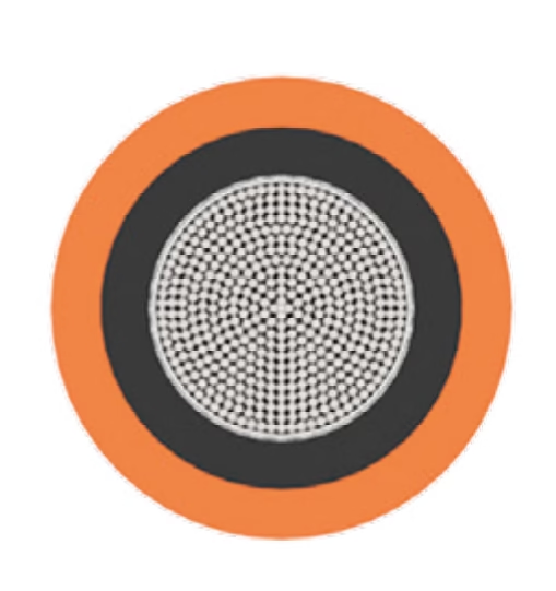
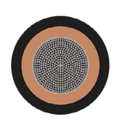
IEC 60332-1-2 cable

To understand tensile strength and why it matters for industrial crane cables, imagine the experience of hanging from a rope. Your body weight creates a downward pulling force—tension—that the rope must support without breaking. If the rope is strong enough, it successfully supports your weight. If the rope is too weak or has internal flaws, it snaps under the load. This pulling force is tensile stress, and it creates mechanical stress fundamentally different from bending stress. When a cable bends, as in drag chain applications, the stress is distributed through the cable's cross-section with the outer surface experiencing tension and the inner surface experiencing compression. Tensile stress, by contrast, is uniform throughout the entire cable cross-section—every fiber of every conductor, every layer of insulation, and every section of the outer sheath must collectively resist the pulling force. Now imagine a cable that has never been designed for sustained vertical loading. A standard flexible control cable like many ÖLFLEX variants is engineered for signal transmission and moderate power delivery in fixed or gently bending installations where the cable's weight and the connected equipment weight are supported by external structures (mounting points, cable trays, junction boxes). Such a cable experiences minimal tensile stress because the infrastructure—not the cable itself—supports the load. However, when that same cable is attached to a crane hook or reeling drum, the situation changes dramatically. The cable must now support the weight of equipment hanging below it, the weight of the cable itself accumulating as the cable extends downward, and dynamic shock loads when equipment is suddenly engaged or when the cable experiences jerking motions from crane acceleration. The cable is subjected to sustained tension for hours during a working day, and it experiences repeated tension cycles as equipment is lifted, held at elevated height, and lowered. This sustained and repetitive tensile loading creates stress states that standard flexible cables cannot safely tolerate. The ÖLFLEX CRANE 4G2.5 is specifically engineered to handle this sustained tensile loading through a special central supporting element (strain relief core), optimized rubber compound formulation, and carefully engineered conductor geometry that will be the focus of this technical guide.

Rubber Reeling Specs: Equivalent Tensile Strength for ÖLFLEX CRANE 4G2.5 0.5kV

To understand tensile strength and why it matters for industrial crane cables, imagine the experience of hanging from a rope. Your body weight creates a downward pulling force—tension—that the rope must support without breaking. If the rope is strong enough, it successfully supports your weight. If the rope is too weak or has internal flaws, it snaps under the load. This pulling force is tensile stress, and it creates mechanical stress fundamentally different from bending stress. When a cable bends, as in drag chain applications, the stress is distributed through the cable’s cross-section with the outer surface experiencing tension and the inner surface experiencing compression. Tensile stress, by contrast, is uniform throughout the entire cable cross-section—every fiber of every conductor, every layer of insulation, and every section of the outer sheath must collectively resist the pulling force. Now imagine a cable that has never been designed for sustained vertical loading. A standard flexible control cable like many ÖLFLEX variants is engineered for signal transmission and moderate power delivery in fixed or gently bending installations where the cable’s weight and the connected equipment weight are supported by external structures (mounting points, cable trays, junction boxes). Such a cable experiences minimal tensile stress because the infrastructure—not the cable itself—supports the load. However, when that same cable is attached to a crane hook or reeling drum, the situation changes dramatically. The cable must now support the weight of equipment hanging below it, the weight of the cable itself accumulating as the cable extends downward, and dynamic shock loads when equipment is suddenly engaged or when the cable experiences jerking motions from crane acceleration. The cable is subjected to sustained tension for hours during a working day, and it experiences repeated tension cycles as equipment is lifted, held at elevated height, and lowered. This sustained and repetitive tensile loading creates stress states that standard flexible cables cannot safely tolerate. The ÖLFLEX CRANE 4G2.5 is specifically engineered to handle this sustained tensile loading through a special central supporting element (strain relief core), optimized rubber compound formulation, and carefully engineered conductor geometry that will be the focus of this technical guide.
To understand why the ÖLFLEX CRANE F 4G16 uses flat geometry rather than the round cross-sections we discussed in previous technical guides, let me start with a fundamental insight about space utilization and mechanical engineering. When a cable delivers electrical power through an overhead crane system—whether a gantry crane moving horizontally across a factory floor, a hoist lifting loads vertically, or an aerial work platform moving in multiple directions—the cable must be routed overhead through a confined space. Picture the challenge: the cable must travel along the length of the crane runway, then hang down to the moving load-handling equipment. This overhead routing space is precious and limited. The crane runway has architectural constraints from building structure. Weather protection enclosures limit available vertical space. Multiple independent circuits might need to be routed in parallel (one cable for hoist movement, another for load rotation, another for operator pendant communication). In this constrained space, a round cable is geometrically inefficient. A round cable with 76-ampere capacity might have a circular cross-section 30+ millimeters in diameter, requiring substantial overhead routing infrastructure and producing significant cable sag that stresses the support structure. A flat cable delivering identical 76-ampere capacity might have a rectangular cross-section of 38 millimeters wide by 13 millimeters thick—same electrical capacity, but dramatically better space utilization. The flat geometry fits within tighter vertical spaces. Multiple flat cables can be stacked side-by-side with their 38-millimeter widths taking minimal combined space. The reduced cable sag from the lighter, more compact design reduces stress on overhead support structures. This is the fundamental advantage of flat cable geometry: superior space utilization without sacrificing electrical performance. However, flat geometry introduces unique engineering challenges that round cables do not have. A round cable bends uniformly in all directions around its circular cross-section. A flat cable bends very differently depending on direction: bending along the wide dimension (38 millimeters) creates different mechanical stress than bending along the thick dimension (13 millimeters). The flat geometry creates stress concentration points at the corners where the wide flat surfaces meet the thin edges. The electrical current distribution becomes non-uniform across the flat conductor—current density is higher in the center of the flat surface and lower at the edges. Engineers must carefully design flat cables to manage these geometric-specific challenges while exploiting the space-utilization advantages. The ÖLFLEX CRANE F 4G16 represents sophisticated engineering optimization that takes advantage of flat geometry benefits while carefully addressing the unique challenges that rectangular cross-sections introduce.

Heavy Duty Festoon: Flat Cable Cross-Reference for LAPP ÖLFLEX CRANE F 4G16

To understand why the ÖLFLEX CRANE F 4G16 uses flat geometry rather than the round cross-sections we discussed in previous technical guides, let me start with a fundamental insight about space utilization and mechanical engineering. When a cable delivers electrical power through an overhead crane system—whether a gantry crane moving horizontally across a factory floor, a hoist lifting loads vertically, or an aerial work platform moving in multiple directions—the cable must be routed overhead through a confined space. Picture the challenge: the cable must travel along the length of the crane runway, then hang down to the moving load-handling equipment. This overhead routing space is precious and limited. The crane runway has architectural constraints from building structure. Weather protection enclosures limit available vertical space. Multiple independent circuits might need to be routed in parallel (one cable for hoist movement, another for load rotation, another for operator pendant communication). In this constrained space, a round cable is geometrically inefficient. A round cable with 76-ampere capacity might have a circular cross-section 30+ millimeters in diameter, requiring substantial overhead routing infrastructure and producing significant cable sag that stresses the support structure. A flat cable delivering identical 76-ampere capacity might have a rectangular cross-section of 38 millimeters wide by 13 millimeters thick—same electrical capacity, but dramatically better space utilization. The flat geometry fits within tighter vertical spaces. Multiple flat cables can be stacked side-by-side with their 38-millimeter widths taking minimal combined space. The reduced cable sag from the lighter, more compact design reduces stress on overhead support structures. This is the fundamental advantage of flat cable geometry: superior space utilization without sacrificing electrical performance. However, flat geometry introduces unique engineering challenges that round cables do not have. A round cable bends uniformly in all directions around its circular cross-section. A flat cable bends very differently depending on direction: bending along the wide dimension (38 millimeters) creates different mechanical stress than bending along the thick dimension (13 millimeters). The flat geometry creates stress concentration points at the corners where the wide flat surfaces meet the thin edges. The electrical current distribution becomes non-uniform across the flat conductor—current density is higher in the center of the flat surface and lower at the edges. Engineers must carefully design flat cables to manage these geometric-specific challenges while exploiting the space-utilization advantages. The ÖLFLEX CRANE F 4G16 represents sophisticated engineering optimization that takes advantage of flat geometry benefits while carefully addressing the unique challenges that rectangular cross-sections introduce.
To understand why the ÖLFLEX HEAT 180 EWKF cable uses silicone and why generic silicone cannot match specialized EWKF performance, let me start with a fundamental question about material chemistry that many engineers never consciously consider: what is the difference between silicone and the polyurethane, polyvinyl chloride, and other organic polymers we discussed in previous technical guides? The answer lies in the fundamental backbone structure of the polymer chain itself. Most common cable insulation materials—polyurethane (PUR), polyvinyl chloride (PVC), thermoplastic elastomer (TPE)—are organic polymers built from long chains of carbon atoms bonded together. Carbon is chemically very stable and provides the flexibility and electrical properties these cables need. However, carbon-based polymers have a critical limitation: at elevated temperatures, the carbon bonds begin breaking down through a process called thermal degradation. As temperature increases, thermal energy causes the chemical bonds holding the polymer chain together to vibrate more intensely. Eventually, if temperature gets high enough, the vibration becomes so vigorous that bonds actually rupture. Once bonds break, the polymer chain fragments into smaller pieces, losing all the properties that made it useful as an insulation material. This thermal breakdown becomes severe around 150°C for most organic polymers. Silicone, by contrast, is built from a fundamentally different backbone: alternating silicon and oxygen atoms (Si-O-Si-O-Si-O...). Silicon-oxygen bonds are significantly more thermally stable than carbon-carbon bonds. The silicon-oxygen bond is stronger and vibrates less readily at high temperatures. As a result, silicone polymers can tolerate sustained temperatures of 180°C, 200°C, or even higher without the carbon-carbon bonds breaking down. This is the fundamental reason silicone is essential for cables used in industrial furnaces, steel mills, and other extreme thermal environments where organic polymers would literally fall apart. Now here is the critical insight for this guide: not all silicone formulations are created equal. Generic silicone, while thermally more stable than organic polymers, still includes various additives and plasticizers that are organic (carbon-based) compounds. These additives can themselves degrade at high temperature, leaching out of the silicone matrix or chemically breaking down and causing the silicone's properties to deteriorate. Specialized EWKF silicone addresses this problem by engineering the entire formulation—not just the silicone backbone but also all the additives, plasticizers, and crosslinking chemistry—to maintain stability at extreme temperatures. This is why EWKF silicone achieves 180°C continuous operation while generic silicone degrades progressively and fails prematurely.

High-Temp Silicon: Cost-Saving Alternative for LAPP ÖLFLEX HEAT 180 EWKF 3G1.5

To understand why the ÖLFLEX HEAT 180 EWKF cable uses silicone and why generic silicone cannot match specialized EWKF performance, let me start with a fundamental question about material chemistry that many engineers never consciously consider: what is the difference between silicone and the polyurethane, polyvinyl chloride, and other organic polymers we discussed in previous technical guides? The answer lies in the fundamental backbone structure of the polymer chain itself. Most common cable insulation materials—polyurethane (PUR), polyvinyl chloride (PVC), thermoplastic elastomer (TPE)—are organic polymers built from long chains of carbon atoms bonded together. Carbon is chemically very stable and provides the flexibility and electrical properties these cables need. However, carbon-based polymers have a critical limitation: at elevated temperatures, the carbon bonds begin breaking down through a process called thermal degradation. As temperature increases, thermal energy causes the chemical bonds holding the polymer chain together to vibrate more intensely. Eventually, if temperature gets high enough, the vibration becomes so vigorous that bonds actually rupture. Once bonds break, the polymer chain fragments into smaller pieces, losing all the properties that made it useful as an insulation material. This thermal breakdown becomes severe around 150°C for most organic polymers. Silicone, by contrast, is built from a fundamentally different backbone: alternating silicon and oxygen atoms (Si-O-Si-O-Si-O…). Silicon-oxygen bonds are significantly more thermally stable than carbon-carbon bonds. The silicon-oxygen bond is stronger and vibrates less readily at high temperatures. As a result, silicone polymers can tolerate sustained temperatures of 180°C, 200°C, or even higher without the carbon-carbon bonds breaking down. This is the fundamental reason silicone is essential for cables used in industrial furnaces, steel mills, and other extreme thermal environments where organic polymers would literally fall apart. Now here is the critical insight for this guide: not all silicone formulations are created equal. Generic silicone, while thermally more stable than organic polymers, still includes various additives and plasticizers that are organic (carbon-based) compounds. These additives can themselves degrade at high temperature, leaching out of the silicone matrix or chemically breaking down and causing the silicone’s properties to deteriorate. Specialized EWKF silicone addresses this problem by engineering the entire formulation—not just the silicone backbone but also all the additives, plasticizers, and crosslinking chemistry—to maintain stability at extreme temperatures. This is why EWKF silicone achieves 180°C continuous operation while generic silicone degrades progressively and fails prematurely.
NSSHÖU cables are designed for power supply applications in mining, quarrying, tunneling, and heavy industrial equipment where extreme mechanical stress and abrasion are expected. These cables can be installed in dry, damp, wet, and hazardous environments but are NOT suitable for drumming applications under tensile loads or for continuous robotic movement in energy chains where highly flexible cables with specific bend cycle ratings are required. NSSHÖU电缆设计用于采矿、采石、隧道和重型工业设备中的供电应用,其中预期会有极端的机械应力和磨损。这些电缆可以安装在干燥、潮湿、湿润和危险环境中,但不适合在拉力负载下的卷筒应用或需要具有特定弯曲周期额定值的高度柔性电缆的连续机器人运动的能量链中。

NSSHÖU Cable Ampacity Table: Current Rating & Correction Factors at 50°C Ambient Temperature

NSSHÖU cables are designed for power supply applications in mining, quarrying, tunneling, and heavy industrial equipment where extreme mechanical stress and abrasion are expected. These cables can be installed in dry, damp, wet, and hazardous environments but are NOT suitable for drumming applications under tensile loads or for continuous robotic movement in energy chains where highly flexible cables with specific bend cycle ratings are required. NSSHÖU电缆设计用于采矿、采石、隧道和重型工业设备中的供电应用,其中预期会有极端的机械应力和磨损。这些电缆可以安装在干燥、潮湿、湿润和危险环境中,但不适合在拉力负载下的卷筒应用或需要具有特定弯曲周期额定值的高度柔性电缆的连续机器人运动的能量链中。
2192Y / H03VVH2-F - Light duty flat cable for pendant drops 218-Y / H03VV-F - Light duty for portable appliances 309-Y / H05V2V2-F - High temperature applications 318-TRS / H05RR-F - Rubber cords for domestic use 318-Y / H05VV-F - Ordinary duty PVC cable

What is BS6500 Cable?

2192Y / H03VVH2-F – Light duty flat cable for pendant drops 218-Y / H03VV-F – Light duty for portable appliances 309-Y / H05V2V2-F – High temperature applications 318-TRS / H05RR-F – Rubber cords for domestic use 318-Y / H05VV-F – Ordinary duty PVC cable
Arc welding power sources, equipment and accessories manufactured in accordance with British Standard BS638, particularly Part 4, covers single-core flexible cables carrying the welding current in metal arc welding circuits. Although the British Standards BS638 has been officially withdrawn, it remains commonly referenced in the welding industry, particularly for cables connecting welding power sources to electrode holders and workpieces.

What is BS638 Part 4 Cable?

Arc welding power sources, equipment and accessories manufactured in accordance with British Standard BS638, particularly Part 4, covers single-core flexible cables carrying the welding current in metal arc welding circuits. Although the British Standards BS638 has been officially withdrawn, it remains commonly referenced in the welding industry, particularly for cables connecting welding power sources to electrode holders and workpieces.
BS6195 Standard covers the requirements for insulated flexible cables and cords typically known as coil end leads. These specialized cables are engineered for permanent and direct connection to coil windings or other electrical equipment, providing the essential flexibility and durability required in demanding industrial environments where motors, generators, transformers, and circuit breakers operate.

What is BS6195 Cable?

BS6195 Standard covers the requirements for insulated flexible cables and cords typically known as coil end leads. These specialized cables are engineered for permanent and direct connection to coil windings or other electrical equipment such as motors, generators, transformers, and circuit breakers.
NSHXAFÖ represents a specialized category of single conductor halogen-free flexible power cables engineered for demanding industrial applications, including wind turbine installations where exceptional flexibility, fire safety, and multi-voltage capability are critical requirements. This cable series spans three voltage classes from 0.6/1 kV through 3.6/6 kV, providing comprehensive solutions for both low and medium voltage power distribution within wind energy systems.

What is NSHXAFÖ 0.6/1 to 3.6/6 kV Wind Turbine Cable?

NSHXAFÖ represents a specialized category of single conductor halogen-free flexible power cables engineered for demanding industrial applications, including wind turbine installations where exceptional flexibility, fire safety, and multi-voltage capability are critical requirements. This cable series spans three voltage classes from 0.6/1 kV through 3.6/6 kV, providing comprehensive solutions for both low and medium voltage power distribution within wind energy systems.
Comprehensive Technical Guide to Halogen-Free Rubber Cables for Wind Energy Applications — Standards, Parameters, and Engineering Specifications

What is H07ZZ-F WIND 450/750V Wind Turbine Cable?

H07ZZ-F WIND represents a specialized category of flexible power cables engineered explicitly for wind turbine installations and renewable energy infrastructure. This cable type combines cross-linked halogen-free compound technology with enhanced torsion resistance, making it indispensable for modern wind energy systems where both electrical performance and fire safety are paramount considerations.