dynamic application cable

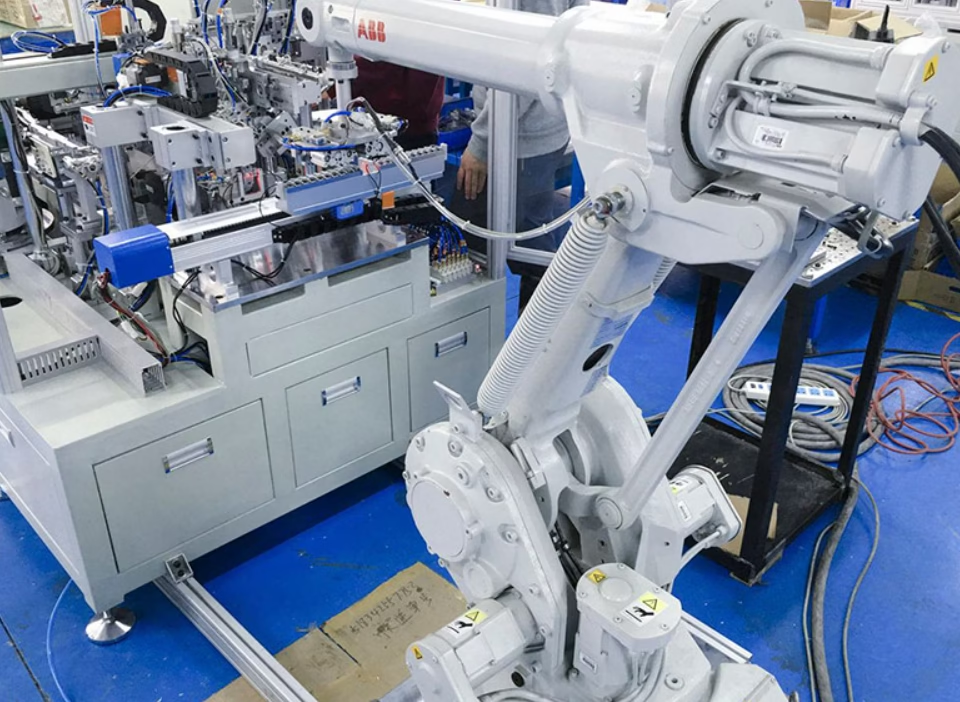
Full decoding of RTS (Robotic/Torsion Standard) conductor class for ultra-fine stranded copper: wire diameter ≤0.10–0.15 mm, 5–10M+ flex cycles, min bend radius 5×OD dynamic, travel speed up to 10 m/s in drag chains. Letter-by-letter decoding of (N)TSCGEWÖU (also searched as NTSCGEWOEU or NTSCGEWOU). Comparison Class 5 → Class 6 → RTS/special. Construction: short-pitch bunch-in-bunch stranding, pressure-extruded sheath, central tension member. Why Class 5 fails in energy chains: bird-caging, wire fracture, contact loss. Sample spec 4G1.5 mm² RTS (300/500 V). Pricing: Igus €8–14/m, Lapp €6–12/m vs Feichun FC-RTS €2.5–5.5/m (45–60% savings). 5-year TCO for 6-axis robot cells. EAC, GOST-R, CE, UL certified.
Проводник медный сверхтонкий многожильный, класс „RTS”: почему он лучше IEC 60228 / DIN VDE 0295 Класс 5

Full decoding of RTS (Robotic/Torsion Standard) conductor class for ultra-fine stranded copper: wire diameter ≤0.10–0.15 mm, 5–10M+ flex cycles, min bend radius 5×OD dynamic, travel speed up to 10 m/s in drag chains. Letter-by-letter decoding of (N)TSCGEWÖU (also searched as NTSCGEWOEU or NTSCGEWOU). Comparison Class 5 → Class 6 → RTS/special. Construction: short-pitch bunch-in-bunch stranding, pressure-extruded sheath, central tension member. Why Class 5 fails in energy chains: bird-caging, wire fracture, contact loss. Sample spec 4G1.5 mm² RTS (300/500 V). Pricing: Igus €8–14/m, Lapp €6–12/m vs Feichun FC-RTS €2.5–5.5/m (45–60% savings). 5-year TCO for 6-axis robot cells. EAC, GOST-R, CE, UL certified.
Electromagnetic compatibility shielding is one of the most misunderstood concepts in industrial cable specification, because understanding it requires integrating knowledge from physics, electrical engineering, materials science, and practical manufacturing. Let me build your understanding of this critical topic from first principles, starting with the fundamental question: what problem does shielding actually solve? In industrial factories, electrical equipment generates electromagnetic noise constantly. Variable frequency drives (VFDs) switching high current on and off create radio-frequency interference. Motors create electromagnetic fields as magnetic flux patterns change. Welding equipment creates severe high-frequency noise. Radio frequency heating systems generate intense electromagnetic energy. This electromagnetic energy radiates outward from all these equipment sources, filling the factory air with invisible electromagnetic waves traveling at the speed of light. Now imagine control cables routed through this electrically noisy environment—cables carrying sensitive information such as sensor measurements, position feedback from encoders, or safety interlock status. When this unshielded cable passes through the electromagnetic noise field, the noise energy couples directly onto the conductor wires inside the cable. The effect is like trying to hear someone whisper in a crowded, loud nightclub—the noise overwhelms the desired signal. A shielded cable solves this problem by surrounding the inner conductors with a conductive barrier—a braid of copper wires—that intercepts the electromagnetic noise before it can couple onto the signal conductors. The shielding acts like a physical wall, or more precisely, like a Faraday cage (a complete electrical enclosure that blocks external electromagnetic fields). However, a Faraday cage is only effective if it has complete coverage—if there are gaps, electromagnetic energy penetrates through the gaps and reaches the inner contents. This is precisely why braid coverage percentage matters so profoundly: it directly determines whether the shielding provides near-complete electromagnetic protection or whether gaps allow significant noise penetration. A cable with 50 percent braid coverage has gaps that allow substantial electromagnetic energy to penetrate. A cable with 85 percent braid coverage has much smaller gaps that allow minimal penetration. The coverage percentage directly determines the shielding effectiveness, measured in decibels, which quantifies how much electromagnetic interference is blocked. Understanding this relationship—how coverage percentage translates into shielding effectiveness—is essential for electrical engineers selecting cables and designing systems that will operate reliably in electromagnetically noisy environments.

EMC Shielding Specs: Tinned Copper Braid Coverage on LAPP ÖLFLEX FD 855 CP 36G0.75

Electromagnetic compatibility shielding is one of the most misunderstood concepts in industrial cable specification, because understanding it requires integrating knowledge from physics, electrical engineering, materials science, and practical manufacturing. Let me build your understanding of this critical topic from first principles, starting with the fundamental question: what problem does shielding actually solve? In industrial factories, electrical equipment generates electromagnetic noise constantly. Variable frequency drives (VFDs) switching high current on and off create radio-frequency interference. Motors create electromagnetic fields as magnetic flux patterns change. Welding equipment creates severe high-frequency noise. Radio frequency heating systems generate intense electromagnetic energy. This electromagnetic energy radiates outward from all these equipment sources, filling the factory air with invisible electromagnetic waves traveling at the speed of light. Now imagine control cables routed through this electrically noisy environment—cables carrying sensitive information such as sensor measurements, position feedback from encoders, or safety interlock status. When this unshielded cable passes through the electromagnetic noise field, the noise energy couples directly onto the conductor wires inside the cable. The effect is like trying to hear someone whisper in a crowded, loud nightclub—the noise overwhelms the desired signal. A shielded cable solves this problem by surrounding the inner conductors with a conductive barrier—a braid of copper wires—that intercepts the electromagnetic noise before it can couple onto the signal conductors. The shielding acts like a physical wall, or more precisely, like a Faraday cage (a complete electrical enclosure that blocks external electromagnetic fields). However, a Faraday cage is only effective if it has complete coverage—if there are gaps, electromagnetic energy penetrates through the gaps and reaches the inner contents. This is precisely why braid coverage percentage matters so profoundly: it directly determines whether the shielding provides near-complete electromagnetic protection or whether gaps allow significant noise penetration. A cable with 50 percent braid coverage has gaps that allow substantial electromagnetic energy to penetrate. A cable with 85 percent braid coverage has much smaller gaps that allow minimal penetration. The coverage percentage directly determines the shielding effectiveness, measured in decibels, which quantifies how much electromagnetic interference is blocked. Understanding this relationship—how coverage percentage translates into shielding effectiveness—is essential for electrical engineers selecting cables and designing systems that will operate reliably in electromagnetically noisy environments.
To understand bending radius in the context of electrical cables, imagine a cable being bent around a curved path. The bending radius is the radius of curvature of that path—specifically, it measures the distance from the center point of the curve to the centerline of the cable as it follows the curve. For a cable being routed around a small pulley or through a tight corner in a power chain, the bending radius is the radius of the pulley or corner curve. The reason bending radius matters profoundly is that when a cable bends, the material on the inside of the curve is compressed and the material on the outside is stretched. This creates mechanical stress throughout the cable's cross-section. The conductors on the inside of the bend are under compressive stress, while those on the outside are under tensile stress. The insulation around the conductors experiences similar stress. If the bending is too tight—if the radius of curvature is too small—the mechanical stress exceeds what the conductor strands and insulation materials can tolerate, leading to permanent deformation, cracking of the insulation, or even breaking of individual conductor strands. Over time, repeated bending at excessive stress levels leads to progressive damage accumulation and eventual cable failure. The specified minimum bending radius is the tightest curve the cable can safely navigate repeatedly without suffering mechanical damage. Understanding this distinction is essential for mechanical and electrical engineers designing cable routing systems for moving equipment.

Bending Radius Guide: How Tight Can You Bend ÖLFLEX FD 855 P 18G1.5 Continuous Flex Cable?

To understand bending radius in the context of electrical cables, imagine a cable being bent around a curved path. The bending radius is the radius of curvature of that path—specifically, it measures the distance from the center point of the curve to the centerline of the cable as it follows the curve. For a cable being routed around a small pulley or through a tight corner in a power chain, the bending radius is the radius of the pulley or corner curve. The reason bending radius matters profoundly is that when a cable bends, the material on the inside of the curve is compressed and the material on the outside is stretched. This creates mechanical stress throughout the cable’s cross-section. The conductors on the inside of the bend are under compressive stress, while those on the outside are under tensile stress. The insulation around the conductors experiences similar stress. If the bending is too tight—if the radius of curvature is too small—the mechanical stress exceeds what the conductor strands and insulation materials can tolerate, leading to permanent deformation, cracking of the insulation, or even breaking of individual conductor strands. Over time, repeated bending at excessive stress levels leads to progressive damage accumulation and eventual cable failure. The specified minimum bending radius is the tightest curve the cable can safely navigate repeatedly without suffering mechanical damage. Understanding this distinction is essential for mechanical and electrical engineers designing cable routing systems for moving equipment.
The dielectric constant of the 3GI3 elastomeric insulation used in (N)3GHSSYCY 3x150+3x25/3 cable is approximately 6.2 to 6.8 at standard reference frequency of 1 kHz, with typical measured value around 6.5 for new cable material. The insulation breakdown voltage (also called dielectric strength or withstand voltage) exceeds 30 kV when measured under controlled laboratory conditions on fresh cable samples with 8 mm insulation thickness, typically achieving 32–38 kV before electrical breakdown occurs.

Dielectric Constant Specs: What is the exact dielectric constant and insulation breakdown voltage for (N)3GHSSYCY 3×150+3×25/3 medium-voltage cable in long VFD motor runs? 

The dielectric constant of the 3GI3 elastomeric insulation used in (N)3GHSSYCY 3×150+3×25/3 cable is approximately 6.2 to 6.8 at standard reference frequency of 1 kHz, with typical measured value around 6.5 for new cable material. The insulation breakdown voltage (also called dielectric strength or withstand voltage) exceeds 30 kV when measured under controlled laboratory conditions on fresh cable samples with 8 mm insulation thickness, typically achieving 32–38 kV before electrical breakdown occurs.
(N)TSCGEWÖU 3x185+3x35/3 6/10kV cables in large-scale mining operations, the outer diameter is not merely a specification number—it is a critical interface parameter determining whether the cable fits your reel system, passes through underground shaft collars, mates with terminal connectors, and allows proper tension management during deployment and retrieval.

What is the Exact Outer Diameter of (N)TSCGEWÖU 3×185+3×35/3 6/10kV Reeling Cable?

(N)TSCGEWÖU 3×185+3×35/3 6/10kV cables in large-scale mining operations, the outer diameter is not merely a specification number—it is a critical interface parameter determining whether the cable fits your reel system, passes through underground shaft collars, mates with terminal connectors, and allows proper tension management during deployment and retrieval.
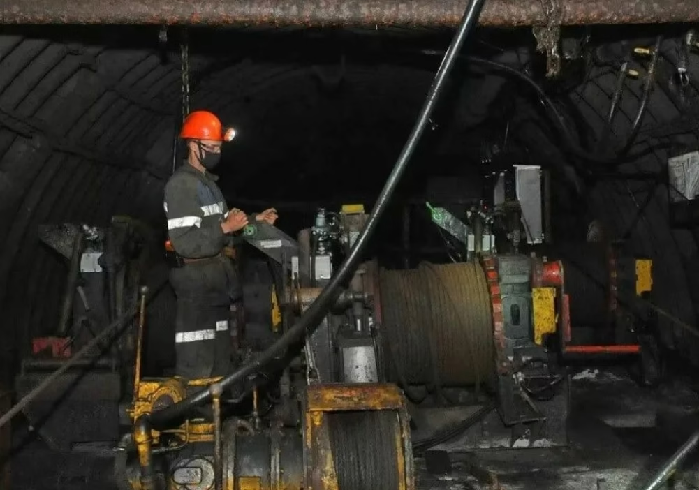
Longwall mining represents the most productive underground coal extraction method available to modern mining operations, with a single longwall face capable of producing over 5,000 tonnes of coal per hour in optimized installations. At the heart of this productivity lies the longwall shearer, a massive mobile machine that travels back and forth along the coal face, cutting coal with rotating drums while advancing through seam heights ranging from 1.6 to 7 meters. The power cables supplying electricity to these shearers operate in one of the most mechanically demanding cable applications in industrial engineering, subjected to continuous motion within cable chain systems (often referred to as "Bretby chains"), constant vibration from cutting operations, tight bending radii as the shearer traverses the face, and the harsh environmental conditions characteristic of underground coal mining.[1] (长壁开采代表了现代采矿作业可用的最具生产力的地下煤炭开采方法,单个长壁工作面在优化安装中每小时可生产超过5000吨煤炭)

Longwall Shearer: What are the advantages of using Type 241 over Type 275 for high-vibration longwall shearer power supplies?

Longwall mining represents the most productive underground coal extraction method available to modern mining operations, with a single longwall face capable of producing over 5,000 tonnes of coal per hour in optimized installations. At the heart of this productivity lies the longwall shearer, a massive mobile machine that travels back and forth along the coal face, cutting coal with rotating drums while advancing through seam heights ranging from 1.6 to 7 meters. The power cables supplying electricity to these shearers operate in one of the most mechanically demanding cable applications in industrial engineering, subjected to continuous motion within cable chain systems (often referred to as “Bretby chains”), constant vibration from cutting operations, tight bending radii as the shearer traverses the face, and the harsh environmental conditions characteristic of underground coal mining.[1] (长壁开采代表了现代采矿作业可用的最具生产力的地下煤炭开采方法,单个长壁工作面在优化安装中每小时可生产超过5000吨煤炭)
The (N)TSCGEWÖU cable manufactured to DIN VDE 0250-813 and the standard power cable manufactured to IEC 60502-2 serve fundamentally different purposes despite both being medium voltage cables. The most critical distinction lies in their mechanical durability design philosophy: VDE 0250 mining cables are engineered for continuous dynamic stress in mobile applications, while IEC 60502-2 cables are optimized for static fixed installations. 按照DIN VDE 0250-813标准生产的(N)TSCGEWÖU电缆与按照IEC 60502-2标准生产的标准电力电缆,尽管都是中压电缆,但其根本用途完全不同。最关键的区别在于它们的机械耐久性设计理念:VDE 0250矿用电缆是为移动应用中的持续动态应力而设计的,而IEC 60502-2电缆则针对静态固定安装进行了优化。

(N)TSCGEWÖU vs. IEC 60502-2: What is the Fundamental Difference in Mechanical Durability?

The (N)TSCGEWÖU cable manufactured to DIN VDE 0250-813 and the standard power cable manufactured to IEC 60502-2 serve fundamentally different purposes despite both being medium voltage cables. The most critical distinction lies in their mechanical durability design philosophy: VDE 0250 mining cables are engineered for continuous dynamic stress in mobile applications, while IEC 60502-2 cables are optimized for static fixed installations. 按照DIN VDE 0250-813标准生产的(N)TSCGEWÖU电缆与按照IEC 60502-2标准生产的标准电力电缆,尽管都是中压电缆,但其根本用途完全不同。最关键的区别在于它们的机械耐久性设计理念:VDE 0250矿用电缆是为移动应用中的持续动态应力而设计的,而IEC 60502-2电缆则针对静态固定安装进行了优化。
What is 600V 2TC Light (600V 2PNCT) Crane Cable? Comprehensive Technical Analysis of 600V Ethylene Propylene Rubber Insulated Polychloroprene Rubber Sheath Cable

What is 600V 2TC Light (600V 2PNCT) Crane Cable?

The 600V 2TC Light (600V 2PNCT) crane cable represents a specialized category of flexible power cables designed specifically for low-voltage mobile equipment applications operating at rated voltages up to 600V. This cable features ethylene propylene rubber (EPR) insulation and polychloroprene rubber (CR) sheath, combining superior electrical performance with exceptional mechanical durability. Manufactured in accordance with JIS C 3327 Japanese Industrial Standard, this cable classification has established itself as the preferred solution for crane systems, reeling applications, and material handling equipment throughout industrial facilities worldwide.