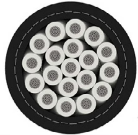
shipboard power cable

Type MMV 8kV 3/C #2 AWG marine and mining medium voltage cable is designed to withstand brief exposure to 250°C (482°F) emergency fault temperatures, specifically for fault durations not exceeding 5 seconds as defined in IEEE 45 and IEC 60092-502 international standards. This 250°C specification represents the absolute maximum temperature that the EPR (ethylene propylene rubber) insulation can tolerate without experiencing irreversible chemical degradation, mechanical property loss, or immediate failure. The cable will remain mechanically and electrically intact during this emergency thermal exposure provided the fault is cleared by protective devices (circuit breakers, fuses, or automatic shutdown systems) before the five-second threshold is exceeded. However, this specification does not mean the cable is unaffected by this thermal stress—even brief exposure to 250°C causes permanent changes to the EPR insulation chemistry, partial annealing of the tinned copper conductors, and measurable loss of mechanical properties. A cable that has experienced a 250°C fault event and survived instantaneous rupture is not necessarily suitable for continued service at full ampacity without comprehensive testing and damage assessment. Understanding what the 250°C specification guarantees and what it does not guarantee is essential for engineers making repair versus replacement decisions following fault events in mining and offshore applications.

Short-Circuit Temperature Limit: Can Type MMV 8kV 3/C #2 AWG Withstand a 250°C Fault?

Type MMV 8kV 3/C #2 AWG marine and mining medium voltage cable is designed to withstand brief exposure to 250°C (482°F) emergency fault temperatures, specifically for fault durations not exceeding 5 seconds as defined in IEEE 45 and IEC 60092-502 international standards. This 250°C specification represents the absolute maximum temperature that the EPR (ethylene propylene rubber) insulation can tolerate without experiencing irreversible chemical degradation, mechanical property loss, or immediate failure. The cable will remain mechanically and electrically intact during this emergency thermal exposure provided the fault is cleared by protective devices (circuit breakers, fuses, or automatic shutdown systems) before the five-second threshold is exceeded. However, this specification does not mean the cable is unaffected by this thermal stress—even brief exposure to 250°C causes permanent changes to the EPR insulation chemistry, partial annealing of the tinned copper conductors, and measurable loss of mechanical properties. A cable that has experienced a 250°C fault event and survived instantaneous rupture is not necessarily suitable for continued service at full ampacity without comprehensive testing and damage assessment. Understanding what the 250°C specification guarantees and what it does not guarantee is essential for engineers making repair versus replacement decisions following fault events in mining and offshore applications.
The ampacity of NEK 606 RFOU 0.6/1kV 4G120 mm² cable in free air at the NEK 606 standard reference condition (45°C ambient, 90°C conductor temperature) is approximately 260 amperes for a single cable installed on an open support structure with unrestricted air circulation. When this same cable is installed in a two-tier (double-banked) configuration where one 4G120 cable sits directly above another with minimal vertical spacing (typical spacing 50–100 mm between outer sheaths), the ampacity of each cable must be derated to approximately 200–215 amperes, representing a derating factor of about 0.78–0.82 or roughly an 18–22% reduction from the free-air rating. When three cables are stacked vertically (three-tier configuration), the derating becomes more severe: the bottom cable sees approximately 0.68–0.72 factor (177–187 A), the middle cable experiences approximately 0.70–0.74 factor (182–192 A), and the top cable maintains approximately 0.80–0.85 factor (208–221 A). The fundamental reason for these derating reductions is that vertically stacked cables cannot dissipate heat as effectively as cables in free air because the upper cables partially shield the lower cables from direct air circulation, creating a thermally interactive system where the waste heat from upper cables warms the ambient environment around lower cables, reducing their cooling effectiveness and thereby their safe operating current capacity.

Double-Banked Cable Trays: What is the ampacity derating factor for NEK 606 RFOU 0.6/1kV 4G120 mm² cables installed in vertically stacked (double-banked) offshore platform configurations?

The ampacity of NEK 606 RFOU 0.6/1kV 4G120 mm² cable in free air at the NEK 606 standard reference condition (45°C ambient, 90°C conductor temperature) is approximately 260 amperes for a single cable installed on an open support structure with unrestricted air circulation. When this same cable is installed in a two-tier (double-banked) configuration where one 4G120 cable sits directly above another with minimal vertical spacing (typical spacing 50–100 mm between outer sheaths), the ampacity of each cable must be derated to approximately 200–215 amperes, representing a derating factor of about 0.78–0.82 or roughly an 18–22% reduction from the free-air rating. When three cables are stacked vertically (three-tier configuration), the derating becomes more severe: the bottom cable sees approximately 0.68–0.72 factor (177–187 A), the middle cable experiences approximately 0.70–0.74 factor (182–192 A), and the top cable maintains approximately 0.80–0.85 factor (208–221 A). The fundamental reason for these derating reductions is that vertically stacked cables cannot dissipate heat as effectively as cables in free air because the upper cables partially shield the lower cables from direct air circulation, creating a thermally interactive system where the waste heat from upper cables warms the ambient environment around lower cables, reducing their cooling effectiveness and thereby their safe operating current capacity.
The base continuous ampacity of a Nexans AmerCable Type MMV 15kV 3/C 4/0 AWG marine medium voltage cable at 90°C conductor temperature is 270 amperes when installed as a single conductor run in air at 45°C ambient temperature, per IEEE 45 marine cable standards. This rating assumes the cable is not bundled with other cables, is laid in a single-layer configuration on a properly ventilated cable tray or support structure, the surrounding air temperature does not exceed 45°C, and no thermal cycling or subsea temperature stratification effects are present. The approximate weight of this cable is 5,083 kg/km (3,418 lbs/1000 ft) for unarmored configurations and 5,750 kg/km (3,864 lbs/1000 ft) for bronze braid-armored versions. The cable features three 4/0 AWG (107.2 mm² equivalent) tinned copper Class 2 stranded conductors with flexible geometry, EPR 90°C thermosetting insulation rated for 100% or 133% voltage levels, symmetrical grounding conductors for balanced common-mode performance, and optional bronze braid armor providing mechanical protection.

Ampacity Chart: How much current can a Type MMV 15kV 3/C 4/0 AWG marine cable carry at 90°C? 

The base continuous ampacity of a Nexans AmerCable Type MMV 15kV 3/C 4/0 AWG marine medium voltage cable at 90°C conductor temperature is 270 amperes when installed as a single conductor run in air at 45°C ambient temperature, per IEEE 45 marine cable standards. This rating assumes the cable is not bundled with other cables, is laid in a single-layer configuration on a properly ventilated cable tray or support structure, the surrounding air temperature does not exceed 45°C, and no thermal cycling or subsea temperature stratification effects are present. The approximate weight of this cable is 5,083 kg/km (3,418 lbs/1000 ft) for unarmored configurations and 5,750 kg/km (3,864 lbs/1000 ft) for bronze braid-armored versions. The cable features three 4/0 AWG (107.2 mm² equivalent) tinned copper Class 2 stranded conductors with flexible geometry, EPR 90°C thermosetting insulation rated for 100% or 133% voltage levels, symmetrical grounding conductors for balanced common-mode performance, and optional bronze braid armor providing mechanical protection.
在海上石油与天然气开采环境中,电缆系统必须承受极端的机械应力、化学腐蚀与温度波动。MOR® Polyrad® XT-125 系列的设计理念便是从这一现实需求出发,通过多层次的材料创新与严格的标准认证体系,为海上平台提供可靠的动力与控制方案。当电气工程师审核技术规格书(Datasheet)时,通常会严格核对以下几个维度以确保系统的安全性、合规性与长期稳定性。

MOR® Polyrad® XT-125: 600V Non-Armored Flexible Marine Power Cables with Superior Mud Oil Resistance and 125°C Continuous Rating for Offshore Drilling Platforms, Mud Motor Drive Systems, and Subsea Power Distribution

Comprehensive technical guide to MOR® Polyrad® XT-125 non-armored flexible marine power cables: Mud Oil-Resistant insulation, 125°C continuous rating, XLPO cross-linked polyolefin, tinned copper braided armor, platform power distribution, and mud motor drive systems for offshore drilling platforms and subsea intervention.
IEC 60092-354 mandates LSZH materials—typically halogen-free compounds based on thermoplastic polyethylene (HTPE), ethylene vinyl acetate (EVA), or polyurethane (PU). These materials meet stringent EN 61034 smoke emission criteria: less than 50% optical density when tested in a closed chamber, and minimal evolution of corrosive gases (measured as hydrochloric acid equivalent per EN 50267-2-1). For additional mechanical protection, ship cables are almost always specified with armoring: a steel wire or steel tape wrapping applied over the jacket.

IEC 60092 MV Cables vs. IEEE 1580 Type MMV: A Specifier’s Guide for Shipboard Power Distribution

IEC 60092-354 mandates LSZH materials—typically halogen-free compounds based on thermoplastic polyethylene (HTPE), ethylene vinyl acetate (EVA), or polyurethane (PU). These materials meet stringent EN 61034 smoke emission criteria: less than 50% optical density when tested in a closed chamber, and minimal evolution of corrosive gases (measured as hydrochloric acid equivalent per EN 50267-2-1). For additional mechanical protection, ship cables are almost always specified with armoring: a steel wire or steel tape wrapping applied over the jacket.
British Standard BS6883 covers the specifications for elastomer insulated cables for fixed wiring in ships (shipwiring) and on mobile and fixed offshore marine units. This standard specifies the requirements and test methods for shipboard fixed wiring of lighting, power, control, instrumentation and propulsion circuits with a voltage rating of up to 8.7/15kV.

What is BS6883 Cable?

BS6883電纜, BS6883船用電纜, 船用電纜, 海上電纜, 船用佈線電纜, 船舶電纜, LSZH電纜, LSHF電纜, 低煙無鹵電纜, EPR船用電纜, 海上電力電纜, 船用電纜, 657TQ電纜, 658TQ電纜, SW4型電纜, SW3型電纜, SW2型電纜, 鎧裝船用電纜, 非鎧裝船用電纜, 鋼絲編織電纜, HOFR電纜, 無鹵電纜, 阻燃船用電纜, 勞氏船級社電纜, DNV電纜, UKOOA電纜, 600/1000V船用電纜, 船用儀表電纜, 海上平台電纜, 鑽井平台電纜, 石油平台電纜, FPSO電纜, 耐火電纜, BS7917電纜, 彈性體絕緣電纜, EPR絕緣電纜, 鍍錫銅船用電纜,BS6883, BS6883 cable, marine cable, offshore cable, shipwiring cable, ship cable, LSZH cable, LSHF cable, low smoke halogen free cable, EPR marine cable, offshore power cable, shipboard cable, 657TQ cable, 658TQ cable, Type SW4 cable, Type SW3 cable, Type SW2 cable, armoured marine cable, unarmoured marine cable, GSWB cable, steel wire braid cable, HOFR cable, halogen free cable, flame retardant marine cable