(N)TSKCGEWÖU

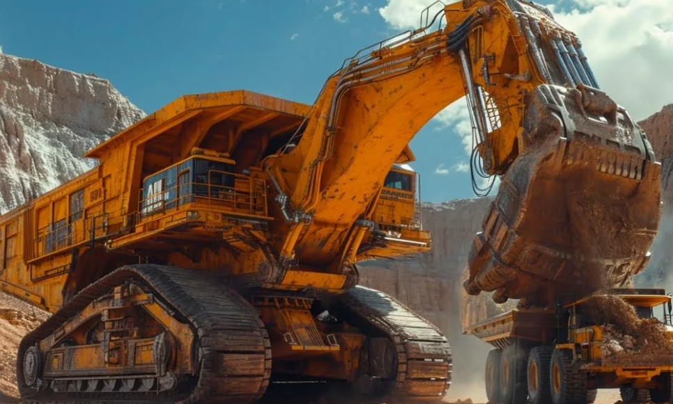
The Pilbara region of Western Australia hosts some of the world's largest iron ore mines operated by BHP, Rio Tinto, and Fortescue. The mining environment is defined by extremes: surface temperatures regularly exceed 45–50°C during summer months, UV radiation intensity is among the highest in Australia, iron ore is extraordinarily hard and sharp-edged (causing accelerated cable abrasion), and equipment operates in remote locations with minimal maintenance infrastructure. 澳洲西部皮尔巴拉地区拥有世界上一些最大的铁矿,由必和必拓、力拓和富瑞斯经营。采矿环境由极端条件定义:夏季地表温度常超45–50°C,紫外线强度是澳洲最高的,铁矿石异常坚硬且边缘锋利(导致电缆加速磨损),设备在维护基础设施最少的偏远位置运行。 Bucket Wheel Excavator Operations: A bucket wheel excavator (BWE) is a massive rotating machine that mines iron ore by continuous removal of overburden and ore. A typical Pilbara BWE operates 24/7 during mine production, with bucket wheel rotation speeds creating enormous dynamic electrical loads. A single large BWE power demand can reach 5–8 megawatts, requiring 22kV or higher voltage transmission from the main mine substation to the mobile machine. Cable Deployment Requirements: BWE power cables are deployed as trailing cables—the cable unrolls from a reeling drum as the BWE advances through the mine pit, accumulating 500+ meters of cable length during extended operation. When the excavator repositions, the cable must be rapidly re-wound under high tension. This extreme dynamic flexing (20,000–50,000 cycles per year) combined with harsh environmental exposure (temperature, UV, abrasion) creates unprecedented cable engineering challenges.

Pilbara Iron Ore Standard: Sourcing (N)TSKCGEWÖU 3×240+3×120/3 22/22kV for Bucket Wheel Excavators

The Pilbara region of Western Australia hosts some of the world’s largest iron ore mines operated by BHP, Rio Tinto, and Fortescue. The mining environment is defined by extremes: surface temperatures regularly exceed 45–50°C during summer months, UV radiation intensity is among the highest in Australia, iron ore is extraordinarily hard and sharp-edged (causing accelerated cable abrasion), and equipment operates in remote locations with minimal maintenance infrastructure. 澳洲西部皮尔巴拉地区拥有世界上一些最大的铁矿,由必和必拓、力拓和富瑞斯经营。采矿环境由极端条件定义:夏季地表温度常超45–50°C,紫外线强度是澳洲最高的,铁矿石异常坚硬且边缘锋利(导致电缆加速磨损),设备在维护基础设施最少的偏远位置运行。 Bucket Wheel Excavator Operations: A bucket wheel excavator (BWE) is a massive rotating machine that mines iron ore by continuous removal of overburden and ore. A typical Pilbara BWE operates 24/7 during mine production, with bucket wheel rotation speeds creating enormous dynamic electrical loads. A single large BWE power demand can reach 5–8 megawatts, requiring 22kV or higher voltage transmission from the main mine substation to the mobile machine. Cable Deployment Requirements: BWE power cables are deployed as trailing cables—the cable unrolls from a reeling drum as the BWE advances through the mine pit, accumulating 500+ meters of cable length during extended operation. When the excavator repositions, the cable must be rapidly re-wound under high tension. This extreme dynamic flexing (20,000–50,000 cycles per year) combined with harsh environmental exposure (temperature, UV, abrasion) creates unprecedented cable engineering challenges.
(N)TSKCGEWÖU 3x150+3x25/3 3.6/6kV cable with split three-part earth conductor is approximately 65 mm (2.56 inches), with a standard tolerance window of ±3.0 mm producing a permissible range of 62.0–68.0 mm. The inner jacket (the intermediate protective layer between the insulation and outer sheath) typically has a nominal thickness of approximately 0.8–1.0 mm, contributing to overall diameter build-up but not typically measured as a separate "inner diameter" in engineering specifications because the inner jacket is not a defined outer boundary—it is a layer embedded within the cable structure. The outer jacket (the final thermosetting rubber compound layer) has a nominal thickness of approximately 2.5–3.0 mm, providing the cable's mechanical interface with the environment. The approximate total weight of this cable is 8,200 kg/km (5,510 lbs/1000 ft), with copper content approximately 4,560 kg/km. It features three 150 mm² Class 5 tinned copper main phase conductors, three strategically distributed 25/3 mm² split earth conductors for electromagnetic symmetry, a 3GI3 high-dielectric EPR insulation system rated for continuous 90°C operation, an anti-torsion braid reinforcement layer, and a 5GM5 thermosetting halogen-free outer sheath providing extreme abrasion and tear resistance.

What is the Inner and Outer Jacket Diameter of (N)TSKCGEWÖU 3×150+3×25/3 3.6/6kV Splittable Earth Cable?

(N)TSKCGEWÖU 3×150+3×25/3 3.6/6kV cable with split three-part earth conductor is approximately 65 mm (2.56 inches), with a standard tolerance window of ±3.0 mm producing a permissible range of 62.0–68.0 mm. The inner jacket (the intermediate protective layer between the insulation and outer sheath) typically has a nominal thickness of approximately 0.8–1.0 mm, contributing to overall diameter build-up but not typically measured as a separate “inner diameter” in engineering specifications because the inner jacket is not a defined outer boundary—it is a layer embedded within the cable structure. The outer jacket (the final thermosetting rubber compound layer) has a nominal thickness of approximately 2.5–3.0 mm, providing the cable’s mechanical interface with the environment. The approximate total weight of this cable is 8,200 kg/km (5,510 lbs/1000 ft), with copper content approximately 4,560 kg/km. It features three 150 mm² Class 5 tinned copper main phase conductors, three strategically distributed 25/3 mm² split earth conductors for electromagnetic symmetry, a 3GI3 high-dielectric EPR insulation system rated for continuous 90°C operation, an anti-torsion braid reinforcement layer, and a 5GM5 thermosetting halogen-free outer sheath providing extreme abrasion and tear resistance.
The minimum bending radius for the (N)TSKCGEWÖU 3x95+3x16/3 3.6/6kV cable ranges from a minimum of approximately 348 millimeters for fixed installations to a maximum of 1,160 millimeters for S-curve transitions and forced-bend applications, with the most common reeling drum application falling in the 725–870 millimeter range. However, these numbers are meaningful only if you understand what they represent, why different installation types require different radii, and what happens to your cable if you bend it tighter than the specified limit. 最小弯曲半径范围从固定敷设的 348 毫米到 S 型转弯的 1,160 毫米不等,卷筒应用通常为 725–870 毫米。

Minimum Bending Radius: How Tight Can You Bend a (N)TSKCGEWÖU 3×95+3×16/3 3.6/6kV Cable?

The minimum bending radius for the (N)TSKCGEWÖU 3×95+3×16/3 3.6/6kV cable ranges from a minimum of approximately 348 millimeters for fixed installations to a maximum of 1,160 millimeters for S-curve transitions and forced-bend applications, with the most common reeling drum application falling in the 725–870 millimeter range. However, these numbers are meaningful only if you understand what they represent, why different installation types require different radii, and what happens to your cable if you bend it tighter than the specified limit. 最小弯曲半径范围从固定敷设的 348 毫米到 S 型转弯的 1,160 毫米不等,卷筒应用通常为 725–870 毫米。
In port machinery, material handling equipment, stacker-reclaimers, festoon systems, and industrial cranes operating at speeds up to 240 meters per minute, trailing cables experience a distinctive and punishing stress pattern called reverse S-bending. The cable is not simply bent in one direction — it repeatedly curves left, then right, then left again, following the path of the equipment as it traverses an S-shaped trajectory or as cable spools alternately bend the cable in opposite directions during reeling and unreeling cycles. This reverse bending motion is fundamentally different from the static or single-direction bending challenges faced by underground mining cables or fixed installations. The cable experiences rapid alternation between tensile and compressive stress on its individual conductors, combined with torsional (twisting) forces that attempt to unwind the cable's spiral structure. For a standard cable, this combination of stresses creates a perfect recipe for premature fatigue failure, conductor breakage, and insulation degradation.

S-Bend Fatigue: Why (N)TSKCGEWÖU Lasts Longer in High-Speed Applications

In port machinery, material handling equipment, stacker-reclaimers, festoon systems, and industrial cranes operating at speeds up to 240 meters per minute, trailing cables experience a distinctive and punishing stress pattern called reverse S-bending. The cable is not simply bent in one direction — it repeatedly curves left, then right, then left again, following the path of the equipment as it traverses an S-shaped trajectory or as cable spools alternately bend the cable in opposite directions during reeling and unreeling cycles. This reverse bending motion is fundamentally different from the static or single-direction bending challenges faced by underground mining cables or fixed installations. The cable experiences rapid alternation between tensile and compressive stress on its individual conductors, combined with torsional (twisting) forces that attempt to unwind the cable’s spiral structure. For a standard cable, this combination of stresses creates a perfect recipe for premature fatigue failure, conductor breakage, and insulation degradation.
A bucket wheel excavator is a remarkable piece of mining equipment: a massive rotating wheel fitted with buckets that continuously scoops material from a mining face, lifts it high into the air, and deposits it onto a conveyor system. The electrical cables that power such equipment face challenges that are fundamentally different from the cables used in stationary equipment or even in traditional draglines and shovels. As the main bucket wheel rotates continuously — sometimes for 12 to 20 hours per day — the flexible power cables that deliver electricity to drive motors must rotate with the wheel while simultaneously being wound and unwound through the cable reel system that connects the mobile equipment to the fixed power supply. This simultaneous rotation and reeling creates torsional stress — twisting force — that attempts to spiral the cable around its own axis. A standard single-sheath cable, designed primarily to withstand tension and bending, will gradually degrade under this torsional loading, with internal conductors ultimately fracturing and failing. A properly designed double-sheath cable with an anti-torsion braid can withstand decades of this continuous torsional punishment without degradation. Understanding why this distinction matters is the key to extending cable life and preventing expensive equipment failures.

(N)TSKCGEWÖU Double-Sheath Design: Why Anti-Torsion Braid is Critical for Bucket Wheel Excavators

A bucket wheel excavator is a remarkable piece of mining equipment: a massive rotating wheel fitted with buckets that continuously scoops material from a mining face, lifts it high into the air, and deposits it onto a conveyor system. The electrical cables that power such equipment face challenges that are fundamentally different from the cables used in stationary equipment or even in traditional draglines and shovels. As the main bucket wheel rotates continuously — sometimes for 12 to 20 hours per day — the flexible power cables that deliver electricity to drive motors must rotate with the wheel while simultaneously being wound and unwound through the cable reel system that connects the mobile equipment to the fixed power supply. This simultaneous rotation and reeling creates torsional stress — twisting force — that attempts to spiral the cable around its own axis. A standard single-sheath cable, designed primarily to withstand tension and bending, will gradually degrade under this torsional loading, with internal conductors ultimately fracturing and failing. A properly designed double-sheath cable with an anti-torsion braid can withstand decades of this continuous torsional punishment without degradation. Understanding why this distinction matters is the key to extending cable life and preventing expensive equipment failures.
In the standardized designation system for medium-voltage reeling cables, the letter "K" in (N)TSKCGEWÖU stands for the German word "Kombination," which in this context means that the cable's earth (grounding) conductors are intentionally split and symmetrically distributed throughout the cable's cross-section, rather than being concentrated in a single conductor or asymmetrically placed. This small designation change — from (N)TSCGEWÖU to (N)TSKCGEWÖU — signals a fundamental rethinking of how the cable responds to mechanical stress, how it manages electrical currents, and critically, how it performs over thousands of duty cycles on monospiral (single-spiral) reeling drums. "K"代表Kombination,意指地线被分裂并对称分布在电缆横截面各处,而非集中在单个导体中。

(N)TSKCGEWÖU vs. (N)TSCGEWÖU: Why Splittable Earth Design Is Mandatory for Monospiral Reeling Drums

In the standardized designation system for medium-voltage reeling cables, the letter “K” in (N)TSKCGEWÖU stands for the German word “Kombination,” which in this context means that the cable’s earth (grounding) conductors are intentionally split and symmetrically distributed throughout the cable’s cross-section, rather than being concentrated in a single conductor or asymmetrically placed. This small designation change — from (N)TSCGEWÖU to (N)TSKCGEWÖU — signals a fundamental rethinking of how the cable responds to mechanical stress, how it manages electrical currents, and critically, how it performs over thousands of duty cycles on monospiral (single-spiral) reeling drums. “K”代表Kombination,意指地线被分裂并对称分布在电缆横截面各处,而非集中在单个导体中。
Cable crushing represents one of the most insidious and costly failure modes in reeling cable systems for container handling cranes, mobile equipment, and industrial material handling applications. When we speak of cable crushing in the context of drum winding systems, we are describing a progressive mechanical failure that occurs when cables wound onto a drum at high tension are later compressed by additional cable layers wound at even higher tension. This creates a compound crushing effect where the inner layers experience compressive forces far exceeding what the cable construction was designed to withstand. Understanding how to prevent this failure mode through proper tension management is essential for ensuring reliable, long-term operation of (N)TSKCGEWÖU cables in demanding crane applications. 电缆挤压代表了集装箱处理起重机、移动设备和工业物料搬运应用中卷筒电缆系统最隐蔽且代价最高的故障模式之一。

What is the Correct Tension Formulation to Prevent “Cable Crushing” on a Monospiral Drum for (N)TSKCGEWÖU?

Cable crushing represents one of the most insidious and costly failure modes in reeling cable systems for container handling cranes, mobile equipment, and industrial material handling applications. When we speak of cable crushing in the context of drum winding systems, we are describing a progressive mechanical failure that occurs when cables wound onto a drum at high tension are later compressed by additional cable layers wound at even higher tension. This creates a compound crushing effect where the inner layers experience compressive forces far exceeding what the cable construction was designed to withstand. Understanding how to prevent this failure mode through proper tension management is essential for ensuring reliable, long-term operation of (N)TSKCGEWÖU cables in demanding crane applications. 电缆挤压代表了集装箱处理起重机、移动设备和工业物料搬运应用中卷筒电缆系统最隐蔽且代价最高的故障模式之一。
Mining, drilling, and tunnelling cables represent a specialized category of electrical cables engineered to withstand the extreme conditions found in extractive industry operations. Unlike standard industrial cables, these cables must endure continuous mechanical stress from reeling and unreeling operations, exposure to ultraviolet radiation in surface mining, salt-water submersion in offshore drilling, contact with oils and greases from machinery, and the abrasive conditions of underground environments. The demanding nature of these applications requires cables with exceptional durability, flexibility, and resistance to environmental factors that would rapidly degrade conventional cables.

What is Mining, Drilling & Tunnelling Cable? Solutions for Surface, Sub-Surface & Underground Operations

(N)3GHSSHCH – 3.6/6kV, 6/10kV, 8.7/15kV, 12/20kV (N)3GHSSYCY – 3.6/6kV, 6/10kV, 8.7/15kV, 12/20kV (N)SSCHÖU-J – 0.6/1kV (N)SHÖU O/J – 0.6/1kV NSSHÖU O/J – 0.6/1kV NSSHÖU 3E – 0.6/1kV NSSHÖU 3E + ST – 0.6/1kV (N)TMCGEWÖU – 3.6/6kV to 18/30kV (N)TSCGEWÖU – 3.6/6kV to 18/30kV (N)TSCGEWÖU ZH – 3.6/6kV to 12/20kV (N)TSCGEWÖU ATB – 3.6/6kV to 12/20kV (N)TSCGEWÖU FO – 3.6/6kV to 12/20kV (N)TSCGEWÖU Submersible – 3.6/6kV to 12/20kV (N)TSKCGEWÖU – 3.6/6kV to 18/30kV (N)TSCGECEWÖU – 3.6/6kV to 12/20kV (N)TSCGECEWÖU ATB – 3.6/6kV to 12/20kV (N)TSCGECEWÖU ATB GCC – 1.8/3kV to 12/20kV (N)TSCGECEWÖU Submersible – 3.6/6kV to 12/20kV (N)TSCGECECWÖU – 3.6/6kV to 12/20kV (N)TSCGECECWÖU ZH – 3.6/6kV to 12/20kV R-(N)TSCGEWÖU + FO – 3.6/6kV to 12/20kV
Crane cables represent a specialized category of heavy-duty flexible cables designed to power and control cranes, hoists, festoons, conveyors, and gantries. Used extensively across heavy industry including mining, marine ports, steel mills, and container terminals, these cables must be exceptionally robust and capable of handling both torsional (twisting) and tensile (pulling) stresses simultaneously. Unlike standard industrial cables, crane cables experience constant reeling, unreeling, and multi-directional movement, requiring specialized constructions with reinforced components and premium materials.

What are Crane Cables?

NTSCGEWÖU cable, TSCGEWÖU cable, TSKCGEWÖU cable, medium voltage crane, MV reeling cable, 6kV crane cable, 10kV crane cable, 20kV crane cable, anti-torsion cable, ATB cable, crane cable, crane power cable, hoist cable, gantry cable, lifting cable, overhead crane cable, tower crane cable, port crane cable, material handling cable, heavy duty crane cable
The 6/10kV voltage rating represents one of the most widely used medium voltage cable classifications for power distribution networks worldwide. These cables serve as the backbone of industrial power systems, connecting generation units to distribution networks and providing power to manufacturing plants, commercial buildings, and infrastructure projects. The 6/10kV designation indicates cables designed for systems where the phase-to-earth voltage (U₀) is 6kV and the phase-to-phase voltage (U) is 10kV, with a maximum system voltage (Um) of 12kV according to IEC 60502-2.

What is 6/10kV Cable?

(N)3GHSSHCH – 3.6/6kV and 6/10kV Cable (N)3GHSSYCY – 3.6/6kV and 6/10kV Cable (N)TMCGEWÖU – 3.6/6kV, 6/10kV, 8.7/15kV Cable (N)TSCGECECWÖU – 3.6/6kV and 6/10kV Cable (N)TSCGECECWÖU – 3.6/6kV and 6/10kV ZH Cable (N)TSCGECEWÖU – 3.6/6kV and 6/10kV Cable (N)TSCGECEWÖU – 3.6/6kV and 6/10kV ATB Cable (N)TSCGECEWÖU – 1.8/3kV, 3.6/6kV and 6/10kV ATB Cable (Ground Check Conductor) (N)TSCGECEWÖU – 3.6/6kV and 6/10kV Submersible Cable (N)TSCGEWÖU – 3.6/6kV, 6/10kV, 8.7/15kV, 12/20kV, 18/30kV Cable (N)TSCGEWÖU – 3.6/6kV and 6/10kV FO Cable R-(N)TSCGEWÖU + FO Cable 3.6/6kV to 12/20kV (N)TSCGEWÖU – 3.6/6kV and 6/10kV ATB Cable (N)TSCGEWÖU – 3.6/6kV and 6/10kV ZH Cable (N)TSCGEWÖU – 3.6/6kV and 6/10kV Submersible Cable (N)TSKCGEWÖU Cable
DIN VDE 0250 German Standard Flexible Power Reeling Cable

What is DIN VDE 0250 Reeling Cables?

DIN VDE 0250 represents the globally recognized German standard for flexible electrical cables designed specifically for cranes, material handling equipment, and mobile machinery applications. As Germany remains the only country to have issued special design regulations for flexible electrical cables covering cranes and material handling equipment, this standard has achieved worldwide acceptance as the ultimate benchmark for tough rubber-sheathed flexible reeling cables.