EMC compliant cable

Full technical breakdown Lapp ÖLFLEX CLASSIC 110 CY 300/500V: shielded multi-core control cable for CNC machine tools, conveyor systems, automation panels. Characteristic transparent PVC outer sheath allows visual inspection of tinned copper braid shield integrity. "CY" designates copper shield (copperScreen) protecting low-voltage control signals from electromagnetic interference (EMC) from nearby power cables, frequency converters, welding equipment, RF sources. Standard configurations: 2–100 cores, 0.5–35 mm² sections with digital marking (black cores + white numbers) + yellow-green earth. Conductor class 5 per VDE 0295 (maximum flexibility), min. bending radius 20× OD in mobile applications. Special PVC insulation (Lapp composition) provides -5°C to +70°C (mobile) / -40°C to +80°C (fixed). Flame retardant IEC 60332-1-2 (self-extinguishing). Tinned copper braid shield density ~85%, effective EMI suppression 50 Hz to several MHz. Transparent sheath is Lapp trademark — allows visual shield inspection without cutting. Russian alternatives: КГВВЭ (usually black/grey sheath, color-coded cores), МКЭШВ (small sections). European standard YSLYCY-JZ from Helukabel, TKD, Faber. FeiChun YSLYCY-JZ — full drop-in equivalent with transparent PVC, digital marking, 85%+ copper braid.
ÖLFLEX CLASSIC 110 CY Экранированный контрольный кабель: прозрачная ПВХ и медная оплётка для защиты от ЭМС — FeiChun YSLYCY-JZ, аналоги Lapp

Full technical breakdown Lapp ÖLFLEX CLASSIC 110 CY 300/500V: shielded multi-core control cable for CNC machine tools, conveyor systems, automation panels. Characteristic transparent PVC outer sheath allows visual inspection of tinned copper braid shield integrity. “CY” designates copper shield (copperScreen) protecting low-voltage control signals from electromagnetic interference (EMC) from nearby power cables, frequency converters, welding equipment, RF sources. Standard configurations: 2–100 cores, 0.5–35 mm² sections with digital marking (black cores + white numbers) + yellow-green earth. Conductor class 5 per VDE 0295 (maximum flexibility), min. bending radius 20× OD in mobile applications. Special PVC insulation (Lapp composition) provides -5°C to +70°C (mobile) / -40°C to +80°C (fixed). Flame retardant IEC 60332-1-2 (self-extinguishing). Tinned copper braid shield density ~85%, effective EMI suppression 50 Hz to several MHz. Transparent sheath is Lapp trademark — allows visual shield inspection without cutting. Russian alternatives: КГВВЭ (usually black/grey sheath, color-coded cores), МКЭШВ (small sections). European standard YSLYCY-JZ from Helukabel, TKD, Faber. FeiChun YSLYCY-JZ — full drop-in equivalent with transparent PVC, digital marking, 85%+ copper braid.
Electromagnetic compatibility shielding is one of the most misunderstood concepts in industrial cable specification, because understanding it requires integrating knowledge from physics, electrical engineering, materials science, and practical manufacturing. Let me build your understanding of this critical topic from first principles, starting with the fundamental question: what problem does shielding actually solve? In industrial factories, electrical equipment generates electromagnetic noise constantly. Variable frequency drives (VFDs) switching high current on and off create radio-frequency interference. Motors create electromagnetic fields as magnetic flux patterns change. Welding equipment creates severe high-frequency noise. Radio frequency heating systems generate intense electromagnetic energy. This electromagnetic energy radiates outward from all these equipment sources, filling the factory air with invisible electromagnetic waves traveling at the speed of light. Now imagine control cables routed through this electrically noisy environment—cables carrying sensitive information such as sensor measurements, position feedback from encoders, or safety interlock status. When this unshielded cable passes through the electromagnetic noise field, the noise energy couples directly onto the conductor wires inside the cable. The effect is like trying to hear someone whisper in a crowded, loud nightclub—the noise overwhelms the desired signal. A shielded cable solves this problem by surrounding the inner conductors with a conductive barrier—a braid of copper wires—that intercepts the electromagnetic noise before it can couple onto the signal conductors. The shielding acts like a physical wall, or more precisely, like a Faraday cage (a complete electrical enclosure that blocks external electromagnetic fields). However, a Faraday cage is only effective if it has complete coverage—if there are gaps, electromagnetic energy penetrates through the gaps and reaches the inner contents. This is precisely why braid coverage percentage matters so profoundly: it directly determines whether the shielding provides near-complete electromagnetic protection or whether gaps allow significant noise penetration. A cable with 50 percent braid coverage has gaps that allow substantial electromagnetic energy to penetrate. A cable with 85 percent braid coverage has much smaller gaps that allow minimal penetration. The coverage percentage directly determines the shielding effectiveness, measured in decibels, which quantifies how much electromagnetic interference is blocked. Understanding this relationship—how coverage percentage translates into shielding effectiveness—is essential for electrical engineers selecting cables and designing systems that will operate reliably in electromagnetically noisy environments.

EMC Shielding Specs: Tinned Copper Braid Coverage on LAPP ÖLFLEX FD 855 CP 36G0.75

Electromagnetic compatibility shielding is one of the most misunderstood concepts in industrial cable specification, because understanding it requires integrating knowledge from physics, electrical engineering, materials science, and practical manufacturing. Let me build your understanding of this critical topic from first principles, starting with the fundamental question: what problem does shielding actually solve? In industrial factories, electrical equipment generates electromagnetic noise constantly. Variable frequency drives (VFDs) switching high current on and off create radio-frequency interference. Motors create electromagnetic fields as magnetic flux patterns change. Welding equipment creates severe high-frequency noise. Radio frequency heating systems generate intense electromagnetic energy. This electromagnetic energy radiates outward from all these equipment sources, filling the factory air with invisible electromagnetic waves traveling at the speed of light. Now imagine control cables routed through this electrically noisy environment—cables carrying sensitive information such as sensor measurements, position feedback from encoders, or safety interlock status. When this unshielded cable passes through the electromagnetic noise field, the noise energy couples directly onto the conductor wires inside the cable. The effect is like trying to hear someone whisper in a crowded, loud nightclub—the noise overwhelms the desired signal. A shielded cable solves this problem by surrounding the inner conductors with a conductive barrier—a braid of copper wires—that intercepts the electromagnetic noise before it can couple onto the signal conductors. The shielding acts like a physical wall, or more precisely, like a Faraday cage (a complete electrical enclosure that blocks external electromagnetic fields). However, a Faraday cage is only effective if it has complete coverage—if there are gaps, electromagnetic energy penetrates through the gaps and reaches the inner contents. This is precisely why braid coverage percentage matters so profoundly: it directly determines whether the shielding provides near-complete electromagnetic protection or whether gaps allow significant noise penetration. A cable with 50 percent braid coverage has gaps that allow substantial electromagnetic energy to penetrate. A cable with 85 percent braid coverage has much smaller gaps that allow minimal penetration. The coverage percentage directly determines the shielding effectiveness, measured in decibels, which quantifies how much electromagnetic interference is blocked. Understanding this relationship—how coverage percentage translates into shielding effectiveness—is essential for electrical engineers selecting cables and designing systems that will operate reliably in electromagnetically noisy environments.
A high-flex control cable is a specialized electrical cable designed to carry low-voltage control signals, sensor data, and feedback information in industrial automation equipment that requires mechanical flexibility for repeated bending and flexing. Unlike power cables that carry large amounts of electrical energy with relatively straightforward requirements, control cables face a different set of engineering challenges: they must maintain signal integrity (the accuracy and clarity of transmitted information) while navigating tight curves in drag chain systems, remain flexible enough to route through space-constrained equipment, and do so at a cost point that makes equipment economically viable for manufacturers and end users. The cost dimension is fundamentally important because control cables represent a significant portion of bill-of-materials cost in industrial automation equipment, especially when a single machine might require dozens of separate control cable runs for sensors, positioning systems, safety interlocks, and feedback mechanisms. Equipment manufacturers constantly seek cost-effective solutions that maintain necessary performance while reducing material expenses. The LAPP ÖLFLEX FD CLASSIC 810 CY 12G1 cable represents a carefully engineered balance point in this cost-performance spectrum: it delivers the essential high-flex capabilities and EMC shielding required for reliable control signal transmission while utilizing material selections and conductor geometries that keep cost significantly lower than premium servo or power cables. Understanding how to specify this cable appropriately, and how to evaluate cost-effective alternatives, enables equipment designers to reduce equipment cost without compromising reliability or performance. This is the practical reality of industrial engineering: making tradeoff decisions that deliver acceptable performance at sustainable cost. The ÖLFLEX FD CLASSIC 810 CY cable is specifically engineered to excel in this practical middle ground between maximum performance and minimum cost.

High-Flex Control Cable Alternative: Cost-Saving Replacement for LAPP ÖLFLEX FD CLASSIC 810 CY 12G1

A high-flex control cable is a specialized electrical cable designed to carry low-voltage control signals, sensor data, and feedback information in industrial automation equipment that requires mechanical flexibility for repeated bending and flexing. Unlike power cables that carry large amounts of electrical energy with relatively straightforward requirements, control cables face a different set of engineering challenges: they must maintain signal integrity (the accuracy and clarity of transmitted information) while navigating tight curves in drag chain systems, remain flexible enough to route through space-constrained equipment, and do so at a cost point that makes equipment economically viable for manufacturers and end users. The cost dimension is fundamentally important because control cables represent a significant portion of bill-of-materials cost in industrial automation equipment, especially when a single machine might require dozens of separate control cable runs for sensors, positioning systems, safety interlocks, and feedback mechanisms. Equipment manufacturers constantly seek cost-effective solutions that maintain necessary performance while reducing material expenses. The LAPP ÖLFLEX FD CLASSIC 810 CY 12G1 cable represents a carefully engineered balance point in this cost-performance spectrum: it delivers the essential high-flex capabilities and EMC shielding required for reliable control signal transmission while utilizing material selections and conductor geometries that keep cost significantly lower than premium servo or power cables. Understanding how to specify this cable appropriately, and how to evaluate cost-effective alternatives, enables equipment designers to reduce equipment cost without compromising reliability or performance. This is the practical reality of industrial engineering: making tradeoff decisions that deliver acceptable performance at sustainable cost. The ÖLFLEX FD CLASSIC 810 CY cable is specifically engineered to excel in this practical middle ground between maximum performance and minimum cost.
The actual current carrying capacity of the ÖLFLEX CLASSIC 110 25G1.5 multicore cable presents an important distinction that often confuses engineering professionals who are unfamiliar with multicore cable ampacity concepts. The baseline ampacity, calculated under idealized conditions where a single conductor is installed in isolation and carries current at 30°C ambient temperature, is approximately 18 amperes per conductor. However, when all twenty-five conductors are bundled together in the cable and simultaneously carry load—as would occur in an industrial facility where a multiconductor cable distributes power or control signals to numerous equipment connection points—the actual safe current rating for each conductor drops dramatically to approximately 7.2 to 8.1 amperes. This profound reduction from 18 amperes (baseline) to 7.2–8.1 amperes (practical) represents the aggregate effect of multiple derating factors that reflect real-world thermal conditions: the thermal coupling between adjacent conductors (where heat generated in one conductor makes it harder for neighboring conductors to dissipate their own heat), the insulating effect of the cable's outer sheath (which traps heat rather than allowing free convection cooling), and the reduced heat dissipation efficiency when multiple cables are installed together in cable trays or conduit. Understanding why this reduction occurs and how to calculate it accurately is essential for electrical engineers designing safe, reliable control systems and power distribution systems using multicore cables.

Ampacity Rating: Current Carrying Capacity for ÖLFLEX CLASSIC 110 25G1.5 Multicore Cable

The actual current carrying capacity of the ÖLFLEX CLASSIC 110 25G1.5 multicore cable presents an important distinction that often confuses engineering professionals who are unfamiliar with multicore cable ampacity concepts. The baseline ampacity, calculated under idealized conditions where a single conductor is installed in isolation and carries current at 30°C ambient temperature, is approximately 18 amperes per conductor. However, when all twenty-five conductors are bundled together in the cable and simultaneously carry load—as would occur in an industrial facility where a multiconductor cable distributes power or control signals to numerous equipment connection points—the actual safe current rating for each conductor drops dramatically to approximately 7.2 to 8.1 amperes. This profound reduction from 18 amperes (baseline) to 7.2–8.1 amperes (practical) represents the aggregate effect of multiple derating factors that reflect real-world thermal conditions: the thermal coupling between adjacent conductors (where heat generated in one conductor makes it harder for neighboring conductors to dissipate their own heat), the insulating effect of the cable’s outer sheath (which traps heat rather than allowing free convection cooling), and the reduced heat dissipation efficiency when multiple cables are installed together in cable trays or conduit. Understanding why this reduction occurs and how to calculate it accurately is essential for electrical engineers designing safe, reliable control systems and power distribution systems using multicore cables.
The nominal outer diameter (OD) of a Lapp ÖLFLEX CLASSIC 110 CY 12G1.5 shielded multi-conductor control cable is approximately 14.8 millimeters (0.583 inches). This specification represents a 12-core cable where each core has a nominal cross-section of 1.5 square millimeters, with one of those cores designated as a green-yellow (dual-color) protective earth/ground conductor in compliance with VDE 0293-334 color coding standards. The cable contains a high-coverage tinned copper braid shield surrounding the insulated conductors, providing exceptional electromagnetic interference (EMC) mitigation with a transfer impedance specification of maximum 250 Ω/km at 30 MHz. The total copper weight (conductor mass) is approximately 280 kilograms per kilometer, while the complete cable (including PVC insulation, outer sheath, and metallic shield) weighs approximately 393 kilograms per kilometer. This cable is designed specifically for control and signal applications in industrial automation environments where electrical noise immunity and mechanical reliability are critical performance requirements.

Direct Equivalent: Cost-Effective Replacement for ÖLFLEX CLASSIC 110 CY 12G1.5 Shielded Cable

The nominal outer diameter (OD) of a Lapp ÖLFLEX CLASSIC 110 CY 12G1.5 shielded multi-conductor control cable is approximately 14.8 millimeters (0.583 inches). This specification represents a 12-core cable where each core has a nominal cross-section of 1.5 square millimeters, with one of those cores designated as a green-yellow (dual-color) protective earth/ground conductor in compliance with VDE 0293-334 color coding standards. The cable contains a high-coverage tinned copper braid shield surrounding the insulated conductors, providing exceptional electromagnetic interference (EMC) mitigation with a transfer impedance specification of maximum 250 Ω/km at 30 MHz. The total copper weight (conductor mass) is approximately 280 kilograms per kilometer, while the complete cable (including PVC insulation, outer sheath, and metallic shield) weighs approximately 393 kilograms per kilometer. This cable is designed specifically for control and signal applications in industrial automation environments where electrical noise immunity and mechanical reliability are critical performance requirements.
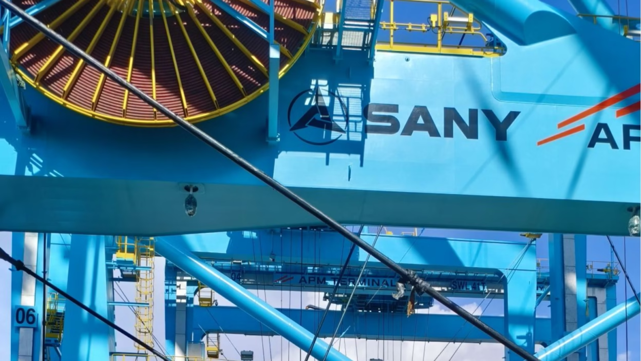
The RHEYFIRM® family represents Nexans' flagship line of flexible medium-voltage reeling cables, engineered specifically for extreme mechanical stress applications including Ship-to-Shore (STS) cranes, Rail Mounted Gantry (RMG) cranes, stacker reclaimers, and heavy mobile mining equipment. The "(S)" designation indicates the symmetrical configuration featuring the distinctive 3+3 core design, where three phase conductors are complemented by three protective earth conductors strategically positioned in the cable interstices. RHEYFIRM®系列是Nexans旗下的中压柔性卷筒电缆产品线,专为极端机械应力应用设计,包括岸桥(STS)起重机、轨道式龙门起重机(RMG)、堆取料机及重型移动采矿设备。"(S)"标识表示对称配置,采用独特的3+3芯设计,三根相线导体与三根保护接地导体战略性地布置在电缆间隙中。

RHEYFIRM® (S) 3+3 Core Design: Why Does Nexans Use Distributed Earth in the (S) Series and How Does It Affect EMC?

The RHEYFIRM® family represents Nexans’ flagship line of flexible medium-voltage reeling cables, engineered specifically for extreme mechanical stress applications including Ship-to-Shore (STS) cranes, Rail Mounted Gantry (RMG) cranes, stacker reclaimers, and heavy mobile mining equipment. The “(S)” designation indicates the symmetrical configuration featuring the distinctive 3+3 core design, where three phase conductors are complemented by three protective earth conductors strategically positioned in the cable interstices. RHEYFIRM®系列是Nexans旗下的中压柔性卷筒电缆产品线,专为极端机械应力应用设计,包括岸桥(STS)起重机、轨道式龙门起重机(RMG)、堆取料机及重型移动采矿设备。”(S)”标识表示对称配置,采用独特的3+3芯设计,三根相线导体与三根保护接地导体战略性地布置在电缆间隙中。