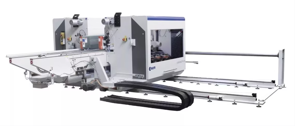
dynamic bending cable

Full technical breakdown Lapp ÖLFLEX FD 855 P 300/500V: high-flex polyurethane cable for drag chains (e-chains) in robotics, linear motion, CNC machinery, automated conveyors. "P" = Polyurethane outer sheath (halogen-free, exceptionally resistant to abrasion, cuts from chain teeth, compression, machine oils). Class 6 copper stranding (ultra-fine, ~0.15 mm wire) per VDE 0295 enables minimum bending radius 5–7.5× OD — among most compact in industry. Insulation: TPE compound acts as "dry lubricant" preventing wire adhesion during millions of flex cycles. PUR sheath extrusion under pressure (gusset-filling) creates tight structure highly resistant to compression and cutting. Temperature: -40°C to +80°C (PUR stays flexible in extreme cold). Max speed: 5 m/s, acceleration to 50 m/s². Free travel distance: up to 100 m. Halogen-free, self-extinguishing. FeiChun Drag Chain PUR Control Cable — full equivalent using identical Class 6 copper, TPE insulation, high-pressure PUR extrusion, certified for 10+ million flex cycles without electrical degradation.

ÖLFLEX FD 855 P Высокогибкий полиуретановый кабель для цепей: инженерия миллионов циклов — FeiChun Drag Chain PUR Cable, аналоги Lapp

Full technical breakdown Lapp ÖLFLEX FD 855 P 300/500V: high-flex polyurethane cable for drag chains (e-chains) in robotics, linear motion, CNC machinery, automated conveyors. “P” = Polyurethane outer sheath (halogen-free, exceptionally resistant to abrasion, cuts from chain teeth, compression, machine oils). Class 6 copper stranding (ultra-fine, ~0.15 mm wire) per VDE 0295 enables minimum bending radius 5–7.5× OD — among most compact in industry. Insulation: TPE compound acts as “dry lubricant” preventing wire adhesion during millions of flex cycles. PUR sheath extrusion under pressure (gusset-filling) creates tight structure highly resistant to compression and cutting. Temperature: -40°C to +80°C (PUR stays flexible in extreme cold). Max speed: 5 m/s, acceleration to 50 m/s². Free travel distance: up to 100 m. Halogen-free, self-extinguishing. FeiChun Drag Chain PUR Control Cable — full equivalent using identical Class 6 copper, TPE insulation, high-pressure PUR extrusion, certified for 10+ million flex cycles without electrical degradation.
Australian mining operations—particularly surface mining and port material handling equipment—rely on festoon systems for continuous power delivery to mobile equipment. A festoon system consists of a stationary overhead cable strung on support structures, with a traveling contact (festoon carriage) that maintains electrical contact with the cable while moving horizontally. The cable must be engineered for continuous flexing, high mechanical stress, and reliable power delivery across distances of 100–500 meters. 澳洲采矿运营——特别是露天采矿和港口物料搬运设备——依赖滑车系统为移动设备提供连续电力。滑车系统由静止的架空电缆组成,支撑在支撑结构上,移动接触件(滑车架)在水平移动时保持与电缆的电气接触。电缆必须设计为可连续弯曲、承受高机械应力、跨越100-500米距离可靠供电。 Continuous Reeling Environment: Unlike trailing cables deployed once and left in place, festoon cables are continuously reeled—moving forward during equipment operation and retracted for repositioning. This creates 10,000–30,000 flex cycles annually. Cable design must accommodate both continuous forward motion (requiring low tension) and rapid retraction (requiring high-speed reeling capacity and mechanical strength).

AS/NZS Upgraded Festoons: Sizing (N)TSFLCGEWÖU 4×120 3.3/3.3kV Flat Reeling Cables

Australian mining operations—particularly surface mining and port material handling equipment—rely on festoon systems for continuous power delivery to mobile equipment. A festoon system consists of a stationary overhead cable strung on support structures, with a traveling contact (festoon carriage) that maintains electrical contact with the cable while moving horizontally. The cable must be engineered for continuous flexing, high mechanical stress, and reliable power delivery across distances of 100–500 meters. 澳洲采矿运营——特别是露天采矿和港口物料搬运设备——依赖滑车系统为移动设备提供连续电力。滑车系统由静止的架空电缆组成,支撑在支撑结构上,移动接触件(滑车架)在水平移动时保持与电缆的电气接触。电缆必须设计为可连续弯曲、承受高机械应力、跨越100-500米距离可靠供电。 Continuous Reeling Environment: Unlike trailing cables deployed once and left in place, festoon cables are continuously reeled—moving forward during equipment operation and retracted for repositioning. This creates 10,000–30,000 flex cycles annually. Cable design must accommodate both continuous forward motion (requiring low tension) and rapid retraction (requiring high-speed reeling capacity and mechanical strength).
The Pilbara region of Western Australia hosts some of the world's largest iron ore mines operated by BHP, Rio Tinto, and Fortescue. The mining environment is defined by extremes: surface temperatures regularly exceed 45–50°C during summer months, UV radiation intensity is among the highest in Australia, iron ore is extraordinarily hard and sharp-edged (causing accelerated cable abrasion), and equipment operates in remote locations with minimal maintenance infrastructure. 澳洲西部皮尔巴拉地区拥有世界上一些最大的铁矿,由必和必拓、力拓和富瑞斯经营。采矿环境由极端条件定义:夏季地表温度常超45–50°C,紫外线强度是澳洲最高的,铁矿石异常坚硬且边缘锋利(导致电缆加速磨损),设备在维护基础设施最少的偏远位置运行。 Bucket Wheel Excavator Operations: A bucket wheel excavator (BWE) is a massive rotating machine that mines iron ore by continuous removal of overburden and ore. A typical Pilbara BWE operates 24/7 during mine production, with bucket wheel rotation speeds creating enormous dynamic electrical loads. A single large BWE power demand can reach 5–8 megawatts, requiring 22kV or higher voltage transmission from the main mine substation to the mobile machine. Cable Deployment Requirements: BWE power cables are deployed as trailing cables—the cable unrolls from a reeling drum as the BWE advances through the mine pit, accumulating 500+ meters of cable length during extended operation. When the excavator repositions, the cable must be rapidly re-wound under high tension. This extreme dynamic flexing (20,000–50,000 cycles per year) combined with harsh environmental exposure (temperature, UV, abrasion) creates unprecedented cable engineering challenges.

Pilbara Iron Ore Standard: Sourcing (N)TSKCGEWÖU 3×240+3×120/3 22/22kV for Bucket Wheel Excavators

The Pilbara region of Western Australia hosts some of the world’s largest iron ore mines operated by BHP, Rio Tinto, and Fortescue. The mining environment is defined by extremes: surface temperatures regularly exceed 45–50°C during summer months, UV radiation intensity is among the highest in Australia, iron ore is extraordinarily hard and sharp-edged (causing accelerated cable abrasion), and equipment operates in remote locations with minimal maintenance infrastructure. 澳洲西部皮尔巴拉地区拥有世界上一些最大的铁矿,由必和必拓、力拓和富瑞斯经营。采矿环境由极端条件定义:夏季地表温度常超45–50°C,紫外线强度是澳洲最高的,铁矿石异常坚硬且边缘锋利(导致电缆加速磨损),设备在维护基础设施最少的偏远位置运行。 Bucket Wheel Excavator Operations: A bucket wheel excavator (BWE) is a massive rotating machine that mines iron ore by continuous removal of overburden and ore. A typical Pilbara BWE operates 24/7 during mine production, with bucket wheel rotation speeds creating enormous dynamic electrical loads. A single large BWE power demand can reach 5–8 megawatts, requiring 22kV or higher voltage transmission from the main mine substation to the mobile machine. Cable Deployment Requirements: BWE power cables are deployed as trailing cables—the cable unrolls from a reeling drum as the BWE advances through the mine pit, accumulating 500+ meters of cable length during extended operation. When the excavator repositions, the cable must be rapidly re-wound under high tension. This extreme dynamic flexing (20,000–50,000 cycles per year) combined with harsh environmental exposure (temperature, UV, abrasion) creates unprecedented cable engineering challenges.
The primary difference between AS/NZS 1802 Type 241 and Type 245 mining cables lies in their internal core configuration and the resulting mechanical flexibility characteristics. Type 241 contains three power cores, three interstitial grounding cores, and one central extensible pilot core (total of seven conductors), while Type 245 contains three power cores, three interstitial grounding cores, and three central extensible pilot cores (total of nine conductors). This seemingly modest difference—replacing one central pilot with three parallel pilots—fundamentally changes how the cable bends, flexes, and responds to the mechanical stresses of underground mining operations. Type 241 is the standard general-purpose feeder cable designed for continuous miners, pump power supplies, and applications where the cable experiences moderate, repetitive flexing but does not encounter the extreme bending and twisting stresses of longwall operations. Type 245 is the high-flexibility shearer cable engineered specifically for longwall shearers and other equipment that demands superior resistance to severe, repetitive bending and the complex rotational stresses that characterize modern longwall mining systems.

Type 241 vs Type 245 AS/NZS 1802 Mining Cables: Complete Technical Comparison Guide with Application-Specific Selection Methodology

The primary difference between AS/NZS 1802 Type 241 and Type 245 mining cables lies in their internal core configuration and the resulting mechanical flexibility characteristics. Type 241 contains three power cores, three interstitial grounding cores, and one central extensible pilot core (total of seven conductors), while Type 245 contains three power cores, three interstitial grounding cores, and three central extensible pilot cores (total of nine conductors). This seemingly modest difference—replacing one central pilot with three parallel pilots—fundamentally changes how the cable bends, flexes, and responds to the mechanical stresses of underground mining operations. Type 241 is the standard general-purpose feeder cable designed for continuous miners, pump power supplies, and applications where the cable experiences moderate, repetitive flexing but does not encounter the extreme bending and twisting stresses of longwall operations. Type 245 is the high-flexibility shearer cable engineered specifically for longwall shearers and other equipment that demands superior resistance to severe, repetitive bending and the complex rotational stresses that characterize modern longwall mining systems.
To understand torsion and why it matters for robotic cables, let me start with a physical experience you might relate to. Imagine holding both ends of a rubber hose and twisting it—rotating one end clockwise while holding the other end still. The hose twists around its axis, and if you twist hard enough, it eventually fails and splits. This twisting action is torsion, and it creates mechanical stress fundamentally different from bending stress. When a cable bends, the stress is primarily tensile and compressive—the outside of the bend stretches while the inside compresses. Torsional stress, by contrast, is a shear stress that acts to rotate the material around the cable's central axis. Imagine the cable's cross-section divided into tiny segments like pie slices. Torsion causes these segments to shear relative to each other—each segment twists slightly relative to its neighbors, accumulating to create total rotation around the cable axis. Now imagine a cable that has never been designed for torsion. A standard control cable like the ÖLFLEX FD series is engineered for bending in drag chain systems—the cable flexes up and down, navigates tight curves, but does not typically experience twisting. The conductor stranding, insulation thickness, and outer sheath are optimized for bending stress tolerance but not designed to handle torsional shear stress. When such a cable is subjected to torsion, internal layers within the cable experience shearing forces that exceed their tolerance. The conductors twist relative to the insulation. The insulation twists relative to the outer sheath. The material bonds between layers experience shear stress. Eventually, micro-cracks develop, the conductor integrity degrades, and the cable fails. Robotic systems create a unique challenge that standard flex cables cannot handle: they require simultaneous bending and torsion. Consider a six-axis industrial robot arm. The arm rotates around multiple joints, and the cable attached to the arm must bend as the arm flexes and also twist as the arm rotates around its axis. At the elbow joint, the cable simultaneously bends and twists. This combined stress is far more demanding than either bending or torsion alone. The ÖLFLEX ROBOT 900 P is specifically engineered to handle this simultaneous bending and torsion through sophisticated material selection and construction design that will be the focus of this technical guide.

Torsion Resistance Check: Upgrading from Standard FD to LAPP ÖLFLEX ROBOT 900 P Equivalents

To understand torsion and why it matters for robotic cables, let me start with a physical experience you might relate to. Imagine holding both ends of a rubber hose and twisting it—rotating one end clockwise while holding the other end still. The hose twists around its axis, and if you twist hard enough, it eventually fails and splits. This twisting action is torsion, and it creates mechanical stress fundamentally different from bending stress. When a cable bends, the stress is primarily tensile and compressive—the outside of the bend stretches while the inside compresses. Torsional stress, by contrast, is a shear stress that acts to rotate the material around the cable’s central axis. Imagine the cable’s cross-section divided into tiny segments like pie slices. Torsion causes these segments to shear relative to each other—each segment twists slightly relative to its neighbors, accumulating to create total rotation around the cable axis. Now imagine a cable that has never been designed for torsion. A standard control cable like the ÖLFLEX FD series is engineered for bending in drag chain systems—the cable flexes up and down, navigates tight curves, but does not typically experience twisting. The conductor stranding, insulation thickness, and outer sheath are optimized for bending stress tolerance but not designed to handle torsional shear stress. When such a cable is subjected to torsion, internal layers within the cable experience shearing forces that exceed their tolerance. The conductors twist relative to the insulation. The insulation twists relative to the outer sheath. The material bonds between layers experience shear stress. Eventually, micro-cracks develop, the conductor integrity degrades, and the cable fails. Robotic systems create a unique challenge that standard flex cables cannot handle: they require simultaneous bending and torsion. Consider a six-axis industrial robot arm. The arm rotates around multiple joints, and the cable attached to the arm must bend as the arm flexes and also twist as the arm rotates around its axis. At the elbow joint, the cable simultaneously bends and twists. This combined stress is far more demanding than either bending or torsion alone. The ÖLFLEX ROBOT 900 P is specifically engineered to handle this simultaneous bending and torsion through sophisticated material selection and construction design that will be the focus of this technical guide.
RHEYFIRM® (S) series reeling cables with 3+3 core distributed earth design exhibit outer diameters ranging from approximately 40.0 mm (for 3×25+3×25/34 mm² configurations at 6/10 kV) to 76.0 mm or larger (for heavy-duty 3×185+3×95/35 mm² configurations at 12/20 kV). The nominal outer diameter depends on the specific conductor cross-section, voltage rating, and insulation thickness selected. For a typical medium-voltage marine and industrial application, a RHEYFIRM® (S) cable rated 3×70+3×35/32 mm² at 6/10 kV exhibits an outer diameter between 52.0 mm and 56.0 mm with approximate total cable weight of 4,300 kg/km (2,890 lbs/1000ft), while the corresponding 12/20 kV variant reaches 62.0 to 67.0 mm outer diameter with weights near 6,800 kg/km (4,570 lbs/1000ft).

RHEYFIRM® (S) 3+3 Core Design: Why Does Nexans Use Distributed Earth in the (S) Series and How Does It Affect EMC?

RHEYFIRM® (S) series reeling cables with 3+3 core distributed earth design exhibit outer diameters ranging from approximately 40.0 mm (for 3×25+3×25/34 mm² configurations at 6/10 kV) to 76.0 mm or larger (for heavy-duty 3×185+3×95/35 mm² configurations at 12/20 kV). The nominal outer diameter depends on the specific conductor cross-section, voltage rating, and insulation thickness selected. For a typical medium-voltage marine and industrial application, a RHEYFIRM® (S) cable rated 3×70+3×35/32 mm² at 6/10 kV exhibits an outer diameter between 52.0 mm and 56.0 mm with approximate total cable weight of 4,300 kg/km (2,890 lbs/1000ft), while the corresponding 12/20 kV variant reaches 62.0 to 67.0 mm outer diameter with weights near 6,800 kg/km (4,570 lbs/1000ft).
4G16 (3 power cores + 1 earth core, 16 mm²) AWG 6 equivalent Outer diameter: 25.5-32.3 mm (nominal 26.5 mm) Copper weight: 614.4 kg/km Total weight: 1200-1380 kg/km Current carrying capacity: 82A (30°C free air) Rated voltage: 0.6/1 kV Conductor: Bare copper or tinned copper, Class 5 (flexible) Temperature range: -25°C to +80°C (mobile/flexing), -40°C to +80°C (fixed) Min bending radius: 8 × OD (about 215 mm) Materials: EPR insulation, dual-layer Neoprene sheath with anti-torsion braid Heavy-duty reeling cable for ports, mining, mobile equipment

Flame Retardant Ratings: Does NSHTÖU-J 4G16 meet IEC 60332-1-2 single wire flame tests?

4G16 (3 power cores + 1 earth core, 16 mm²) AWG 6 equivalent Outer diameter: 25.5-32.3 mm (nominal 26.5 mm) Copper weight: 614.4 kg/km Total weight: 1200-1380 kg/km Current carrying capacity: 82A (30°C free air) Rated voltage: 0.6/1 kV Conductor: Bare copper or tinned copper, Class 5 (flexible) Temperature range: -25°C to +80°C (mobile/flexing), -40°C to +80°C (fixed) Min bending radius: 8 × OD (about 215 mm) Materials: EPR insulation, dual-layer Neoprene sheath with anti-torsion braid Heavy-duty reeling cable for ports, mining, mobile equipment
The maximum pulling tension for NSHTÖU-J 5G16 0.6/1kV cable is absolutely limited to 1,200 newtons of axial tensile load under the VDE 0250-814 standard specification. This maximum is calculated as 15 N/mm² tensile stress multiplied by the total cross-sectional area of the five main copper conductors (five cores × 16 mm² = 80 mm² total), yielding 15 × 80 = 1,200 newtons. This is not a casual guideline or general recommendation—it is the absolute mechanical failure point beyond which the copper conductors begin plastic deformation and eventual rupture. For practical field deployment, however, the safe operating pulling tension should be substantially lower, typically in the range of 600–900 newtons depending on the specific installation scenario, representing a safety factor of 1.3–2.0 applied against the 1,200 newton absolute maximum. The reasoning is straightforward: you never want to operate consistently at the edge of mechanical failure, where even small unanticipated additional loads could cause catastrophic failure. Instead, you design systems to operate comfortably within safe margins where occasional transient overloads can be tolerated without damage.

Maximum Pulling Tension: What is the exact maximum safe pulling load and tensile strength specification for NSHTÖU-J 5G16 0.6/1kV low-voltage reeling cables in heavy machinery and port crane applications?

The maximum pulling tension for NSHTÖU-J 5G16 0.6/1kV cable is absolutely limited to 1,200 newtons of axial tensile load under the VDE 0250-814 standard specification. This maximum is calculated as 15 N/mm² tensile stress multiplied by the total cross-sectional area of the five main copper conductors (five cores × 16 mm² = 80 mm² total), yielding 15 × 80 = 1,200 newtons. This is not a casual guideline or general recommendation—it is the absolute mechanical failure point beyond which the copper conductors begin plastic deformation and eventual rupture. For practical field deployment, however, the safe operating pulling tension should be substantially lower, typically in the range of 600–900 newtons depending on the specific installation scenario, representing a safety factor of 1.3–2.0 applied against the 1,200 newton absolute maximum. The reasoning is straightforward: you never want to operate consistently at the edge of mechanical failure, where even small unanticipated additional loads could cause catastrophic failure. Instead, you design systems to operate comfortably within safe margins where occasional transient overloads can be tolerated without damage.