bare copper stranded wire

To understand torsion and why it matters for robotic cables, let me start with a physical experience you might relate to. Imagine holding both ends of a rubber hose and twisting it—rotating one end clockwise while holding the other end still. The hose twists around its axis, and if you twist hard enough, it eventually fails and splits. This twisting action is torsion, and it creates mechanical stress fundamentally different from bending stress. When a cable bends, the stress is primarily tensile and compressive—the outside of the bend stretches while the inside compresses. Torsional stress, by contrast, is a shear stress that acts to rotate the material around the cable's central axis. Imagine the cable's cross-section divided into tiny segments like pie slices. Torsion causes these segments to shear relative to each other—each segment twists slightly relative to its neighbors, accumulating to create total rotation around the cable axis. Now imagine a cable that has never been designed for torsion. A standard control cable like the ÖLFLEX FD series is engineered for bending in drag chain systems—the cable flexes up and down, navigates tight curves, but does not typically experience twisting. The conductor stranding, insulation thickness, and outer sheath are optimized for bending stress tolerance but not designed to handle torsional shear stress. When such a cable is subjected to torsion, internal layers within the cable experience shearing forces that exceed their tolerance. The conductors twist relative to the insulation. The insulation twists relative to the outer sheath. The material bonds between layers experience shear stress. Eventually, micro-cracks develop, the conductor integrity degrades, and the cable fails. Robotic systems create a unique challenge that standard flex cables cannot handle: they require simultaneous bending and torsion. Consider a six-axis industrial robot arm. The arm rotates around multiple joints, and the cable attached to the arm must bend as the arm flexes and also twist as the arm rotates around its axis. At the elbow joint, the cable simultaneously bends and twists. This combined stress is far more demanding than either bending or torsion alone. The ÖLFLEX ROBOT 900 P is specifically engineered to handle this simultaneous bending and torsion through sophisticated material selection and construction design that will be the focus of this technical guide.
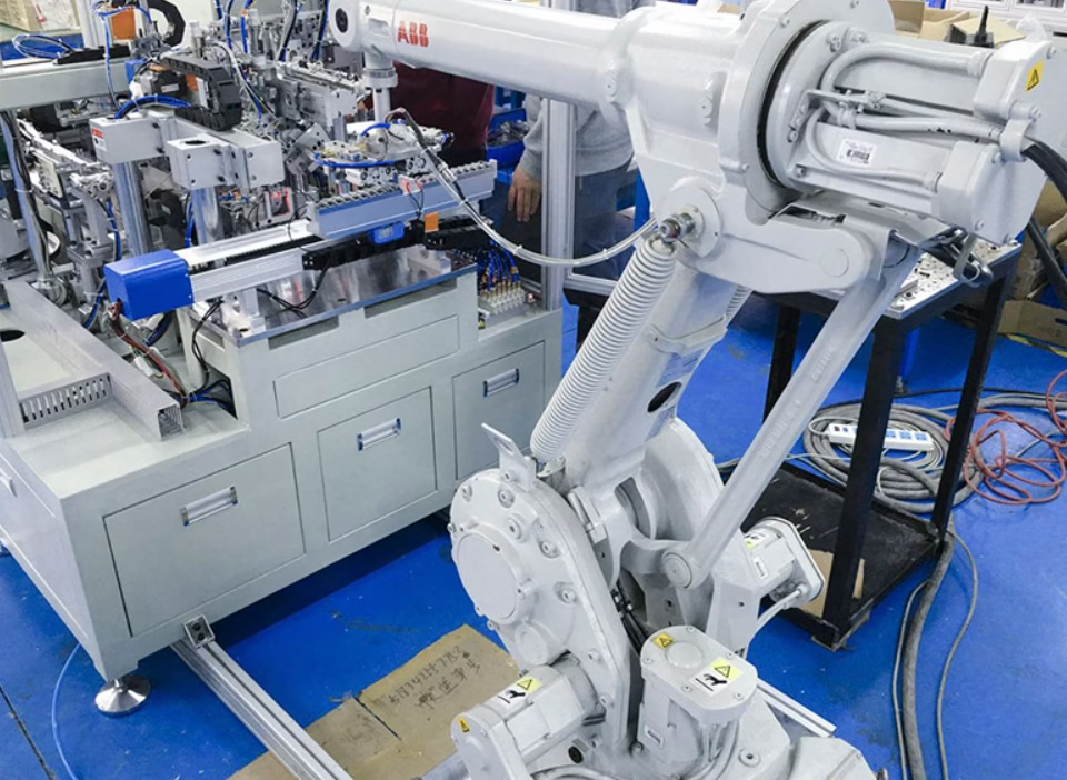
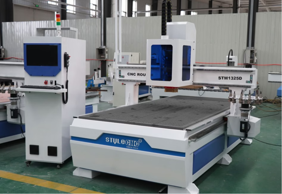
Torsion Resistance Check: Upgrading from Standard FD to LAPP ÖLFLEX ROBOT 900 P Equivalents

To understand torsion and why it matters for robotic cables, let me start with a physical experience you might relate to. Imagine holding both ends of a rubber hose and twisting it—rotating one end clockwise while holding the other end still. The hose twists around its axis, and if you twist hard enough, it eventually fails and splits. This twisting action is torsion, and it creates mechanical stress fundamentally different from bending stress. When a cable bends, the stress is primarily tensile and compressive—the outside of the bend stretches while the inside compresses. Torsional stress, by contrast, is a shear stress that acts to rotate the material around the cable’s central axis. Imagine the cable’s cross-section divided into tiny segments like pie slices. Torsion causes these segments to shear relative to each other—each segment twists slightly relative to its neighbors, accumulating to create total rotation around the cable axis. Now imagine a cable that has never been designed for torsion. A standard control cable like the ÖLFLEX FD series is engineered for bending in drag chain systems—the cable flexes up and down, navigates tight curves, but does not typically experience twisting. The conductor stranding, insulation thickness, and outer sheath are optimized for bending stress tolerance but not designed to handle torsional shear stress. When such a cable is subjected to torsion, internal layers within the cable experience shearing forces that exceed their tolerance. The conductors twist relative to the insulation. The insulation twists relative to the outer sheath. The material bonds between layers experience shear stress. Eventually, micro-cracks develop, the conductor integrity degrades, and the cable fails. Robotic systems create a unique challenge that standard flex cables cannot handle: they require simultaneous bending and torsion. Consider a six-axis industrial robot arm. The arm rotates around multiple joints, and the cable attached to the arm must bend as the arm flexes and also twist as the arm rotates around its axis. At the elbow joint, the cable simultaneously bends and twists. This combined stress is far more demanding than either bending or torsion alone. The ÖLFLEX ROBOT 900 P is specifically engineered to handle this simultaneous bending and torsion through sophisticated material selection and construction design that will be the focus of this technical guide.
Electromagnetic compatibility shielding is one of the most misunderstood concepts in industrial cable specification, because understanding it requires integrating knowledge from physics, electrical engineering, materials science, and practical manufacturing. Let me build your understanding of this critical topic from first principles, starting with the fundamental question: what problem does shielding actually solve? In industrial factories, electrical equipment generates electromagnetic noise constantly. Variable frequency drives (VFDs) switching high current on and off create radio-frequency interference. Motors create electromagnetic fields as magnetic flux patterns change. Welding equipment creates severe high-frequency noise. Radio frequency heating systems generate intense electromagnetic energy. This electromagnetic energy radiates outward from all these equipment sources, filling the factory air with invisible electromagnetic waves traveling at the speed of light. Now imagine control cables routed through this electrically noisy environment—cables carrying sensitive information such as sensor measurements, position feedback from encoders, or safety interlock status. When this unshielded cable passes through the electromagnetic noise field, the noise energy couples directly onto the conductor wires inside the cable. The effect is like trying to hear someone whisper in a crowded, loud nightclub—the noise overwhelms the desired signal. A shielded cable solves this problem by surrounding the inner conductors with a conductive barrier—a braid of copper wires—that intercepts the electromagnetic noise before it can couple onto the signal conductors. The shielding acts like a physical wall, or more precisely, like a Faraday cage (a complete electrical enclosure that blocks external electromagnetic fields). However, a Faraday cage is only effective if it has complete coverage—if there are gaps, electromagnetic energy penetrates through the gaps and reaches the inner contents. This is precisely why braid coverage percentage matters so profoundly: it directly determines whether the shielding provides near-complete electromagnetic protection or whether gaps allow significant noise penetration. A cable with 50 percent braid coverage has gaps that allow substantial electromagnetic energy to penetrate. A cable with 85 percent braid coverage has much smaller gaps that allow minimal penetration. The coverage percentage directly determines the shielding effectiveness, measured in decibels, which quantifies how much electromagnetic interference is blocked. Understanding this relationship—how coverage percentage translates into shielding effectiveness—is essential for electrical engineers selecting cables and designing systems that will operate reliably in electromagnetically noisy environments.

EMC Shielding Specs: Tinned Copper Braid Coverage on LAPP ÖLFLEX FD 855 CP 36G0.75

Electromagnetic compatibility shielding is one of the most misunderstood concepts in industrial cable specification, because understanding it requires integrating knowledge from physics, electrical engineering, materials science, and practical manufacturing. Let me build your understanding of this critical topic from first principles, starting with the fundamental question: what problem does shielding actually solve? In industrial factories, electrical equipment generates electromagnetic noise constantly. Variable frequency drives (VFDs) switching high current on and off create radio-frequency interference. Motors create electromagnetic fields as magnetic flux patterns change. Welding equipment creates severe high-frequency noise. Radio frequency heating systems generate intense electromagnetic energy. This electromagnetic energy radiates outward from all these equipment sources, filling the factory air with invisible electromagnetic waves traveling at the speed of light. Now imagine control cables routed through this electrically noisy environment—cables carrying sensitive information such as sensor measurements, position feedback from encoders, or safety interlock status. When this unshielded cable passes through the electromagnetic noise field, the noise energy couples directly onto the conductor wires inside the cable. The effect is like trying to hear someone whisper in a crowded, loud nightclub—the noise overwhelms the desired signal. A shielded cable solves this problem by surrounding the inner conductors with a conductive barrier—a braid of copper wires—that intercepts the electromagnetic noise before it can couple onto the signal conductors. The shielding acts like a physical wall, or more precisely, like a Faraday cage (a complete electrical enclosure that blocks external electromagnetic fields). However, a Faraday cage is only effective if it has complete coverage—if there are gaps, electromagnetic energy penetrates through the gaps and reaches the inner contents. This is precisely why braid coverage percentage matters so profoundly: it directly determines whether the shielding provides near-complete electromagnetic protection or whether gaps allow significant noise penetration. A cable with 50 percent braid coverage has gaps that allow substantial electromagnetic energy to penetrate. A cable with 85 percent braid coverage has much smaller gaps that allow minimal penetration. The coverage percentage directly determines the shielding effectiveness, measured in decibels, which quantifies how much electromagnetic interference is blocked. Understanding this relationship—how coverage percentage translates into shielding effectiveness—is essential for electrical engineers selecting cables and designing systems that will operate reliably in electromagnetically noisy environments.
A high-flex control cable is a specialized electrical cable designed to carry low-voltage control signals, sensor data, and feedback information in industrial automation equipment that requires mechanical flexibility for repeated bending and flexing. Unlike power cables that carry large amounts of electrical energy with relatively straightforward requirements, control cables face a different set of engineering challenges: they must maintain signal integrity (the accuracy and clarity of transmitted information) while navigating tight curves in drag chain systems, remain flexible enough to route through space-constrained equipment, and do so at a cost point that makes equipment economically viable for manufacturers and end users. The cost dimension is fundamentally important because control cables represent a significant portion of bill-of-materials cost in industrial automation equipment, especially when a single machine might require dozens of separate control cable runs for sensors, positioning systems, safety interlocks, and feedback mechanisms. Equipment manufacturers constantly seek cost-effective solutions that maintain necessary performance while reducing material expenses. The LAPP ÖLFLEX FD CLASSIC 810 CY 12G1 cable represents a carefully engineered balance point in this cost-performance spectrum: it delivers the essential high-flex capabilities and EMC shielding required for reliable control signal transmission while utilizing material selections and conductor geometries that keep cost significantly lower than premium servo or power cables. Understanding how to specify this cable appropriately, and how to evaluate cost-effective alternatives, enables equipment designers to reduce equipment cost without compromising reliability or performance. This is the practical reality of industrial engineering: making tradeoff decisions that deliver acceptable performance at sustainable cost. The ÖLFLEX FD CLASSIC 810 CY cable is specifically engineered to excel in this practical middle ground between maximum performance and minimum cost.

High-Flex Control Cable Alternative: Cost-Saving Replacement for LAPP ÖLFLEX FD CLASSIC 810 CY 12G1

A high-flex control cable is a specialized electrical cable designed to carry low-voltage control signals, sensor data, and feedback information in industrial automation equipment that requires mechanical flexibility for repeated bending and flexing. Unlike power cables that carry large amounts of electrical energy with relatively straightforward requirements, control cables face a different set of engineering challenges: they must maintain signal integrity (the accuracy and clarity of transmitted information) while navigating tight curves in drag chain systems, remain flexible enough to route through space-constrained equipment, and do so at a cost point that makes equipment economically viable for manufacturers and end users. The cost dimension is fundamentally important because control cables represent a significant portion of bill-of-materials cost in industrial automation equipment, especially when a single machine might require dozens of separate control cable runs for sensors, positioning systems, safety interlocks, and feedback mechanisms. Equipment manufacturers constantly seek cost-effective solutions that maintain necessary performance while reducing material expenses. The LAPP ÖLFLEX FD CLASSIC 810 CY 12G1 cable represents a carefully engineered balance point in this cost-performance spectrum: it delivers the essential high-flex capabilities and EMC shielding required for reliable control signal transmission while utilizing material selections and conductor geometries that keep cost significantly lower than premium servo or power cables. Understanding how to specify this cable appropriately, and how to evaluate cost-effective alternatives, enables equipment designers to reduce equipment cost without compromising reliability or performance. This is the practical reality of industrial engineering: making tradeoff decisions that deliver acceptable performance at sustainable cost. The ÖLFLEX FD CLASSIC 810 CY cable is specifically engineered to excel in this practical middle ground between maximum performance and minimum cost.
The nominal outer diameter (OD) of a LAPP ÖLFLEX CLASSIC 115 CY 4G1.5 VDE 0250 four-conductor shielded control cable (Article number 1136304) is precisely 8.2 millimeters (0.323 inches), representing one of the most compact shielded multi-conductor control cables available in the industrial market. This exceptionally small diameter represents the deliberate design philosophy behind the CLASSIC 115 series: eliminating the inner protective sheath layer found in many competing control cables, thereby minimizing overall cable diameter while maintaining complete EMC shielding through a high-coverage tinned copper braided shield. The cable contains exactly four conductors, each with a 1.5 square millimeter cross-sectional area (the 4G1.5 designation), with one conductor specifically designated as the green-yellow protective earth/ground conductor per VDE 0293-308 color coding standards. The total copper conductor mass is approximately 100 kilograms per kilometer, while the complete assembled cable including PVC insulation, outer sheath, and braided copper shield weighs only approximately 135 kilograms per kilometer—among the lightest shielded four-conductor cables available for control applications. This compact, lightweight design makes the ÖLFLEX CLASSIC 115 CY ideally suited for space-constrained installations such as densely wired control panels, measurement and control technology systems, data processing equipment, and industrial machinery where cable routing must navigate tight spaces and equipment enclosure penetrations with minimal material volume.

VDE Cross-Reference: Drop-in Alternative for ÖLFLEX CLASSIC 115 CY 4G1.5 VDE 0250

The nominal outer diameter (OD) of a LAPP ÖLFLEX CLASSIC 115 CY 4G1.5 VDE 0250 four-conductor shielded control cable (Article number 1136304) is precisely 8.2 millimeters (0.323 inches), representing one of the most compact shielded multi-conductor control cables available in the industrial market. This exceptionally small diameter represents the deliberate design philosophy behind the CLASSIC 115 series: eliminating the inner protective sheath layer found in many competing control cables, thereby minimizing overall cable diameter while maintaining complete EMC shielding through a high-coverage tinned copper braided shield. The cable contains exactly four conductors, each with a 1.5 square millimeter cross-sectional area (the 4G1.5 designation), with one conductor specifically designated as the green-yellow protective earth/ground conductor per VDE 0293-308 color coding standards. The total copper conductor mass is approximately 100 kilograms per kilometer, while the complete assembled cable including PVC insulation, outer sheath, and braided copper shield weighs only approximately 135 kilograms per kilometer—among the lightest shielded four-conductor cables available for control applications. This compact, lightweight design makes the ÖLFLEX CLASSIC 115 CY ideally suited for space-constrained installations such as densely wired control panels, measurement and control technology systems, data processing equipment, and industrial machinery where cable routing must navigate tight spaces and equipment enclosure penetrations with minimal material volume.